

Toyota Prius: Brake Fluid
Components
COMPONENTS
ILLUSTRATION
|
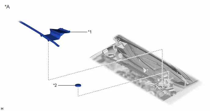
*A |
for M20A-FXS |
- |
- |
|
*1 |
CENTER COWL TOP VENTILATOR LOUVER |
*2 |
BRAKE MASTER CYLINDER RESERVOIR FILLER CAP ASSEMBLY |
ILLUSTRATION
|
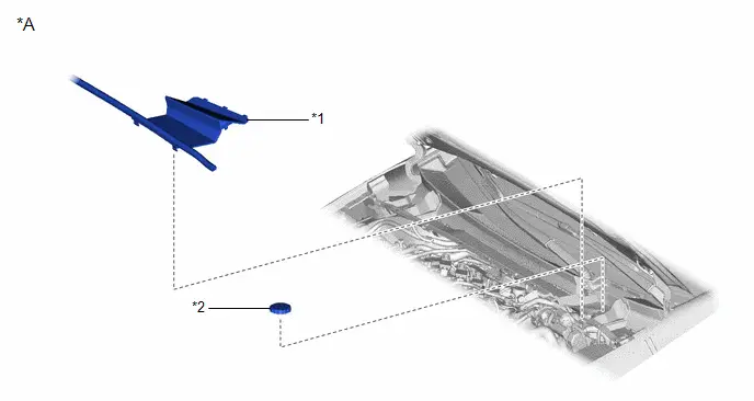
*A |
for 2ZR-FXE |
- |
- |
|
*1 |
CENTER COWL TOP VENTILATOR LOUVER |
*2 |
BRAKE MASTER CYLINDER RESERVOIR FILLER CAP ASSEMBLY |
ILLUSTRATION
|
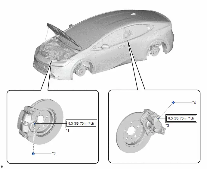
*1 |
FRONT DISC BRAKE BLEEDER PLUG |
*2 |
FRONT DISC BRAKE BLEEDER PLUG CAP |
|
*3 |
REAR DISC BRAKE BLEEDER PLUG |
*4 |
REAR DISC BRAKE BLEEDER PLUG CAP |
 |
Tightening torque for "Major areas involving basic vehicle performance such as moving/turning/stopping": N*m (kgf*cm, ft.*lbf) |
- |
- |
Replacement
REPLACEMENT
CAUTION / NOTICE / HINT
The necessary procedures (adjustment, calibration, initialization, or registration) that must be performed after parts are removed and installed, or replaced during brake fluid replacement are shown below.
Necessary Procedures After Parts Removed/Installed/Replaced|
Replaced Part or Performed Procedure |
Necessary Procedure |
Effect/Inoperative Function when Necessary Procedure not Performed |
Link |
|---|---|---|---|
| *1: Also necessary after performing a tire rotation.
*2: It is not necessary to perform this procedure if the tire pressure warning valve and transmitters are installed to the same location. *3: The vehicle height changes because of tire replacement. |
|||
|
Tires |
|
Tire Pressure Warning System |
Refer to Procedures Necessary When Replacing Parts (for Tire Pressure Warning System)
|
|
Rear television camera assembly optical axis (Back camera position setting)*3 |
Parking Assist Monitor System |
|
|
|
Parking assist ECU initialization*3 |
Panoramic View Monitor System |
|
|
|
Advanced Park |
|
||


CAUTION / NOTICE / HINT
NOTICE:
- Perform fluid replacement with park (P) selected and the parking brake applied.
- Perform fluid replacement while maintaining the brake fluid level between the MAX and MIN lines on the brake fluid reservoir.
- In the process of replacing the brake fluid, DTCs may be stored. Clear the DTCs after brake fluid replacement is complete, and when prompted to do so during the procedure.
- If brake fluid air bleeding is not completed, the warning light will illuminate. In this case, perform brake fluid air bleeding again.
- Do not allow brake fluid to contact any painted surface. If brake fluid leaks onto any painted surface, immediately wash it off.
- When performing fluid replacement, do not continuously operate the pump motor for more than 120 seconds. If the pump motor is operated for more than 120 seconds, release the brake pedal to stop operation of the pump in order to prevent damage to the pump motor.
HINT:
There are 2 ways of brake fluid replacement: using the GTS or not using the GTS.
PROCEDURE
1. REPLACE BRAKE FLUID (When Using the GTS)
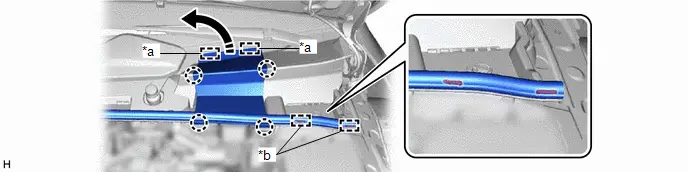
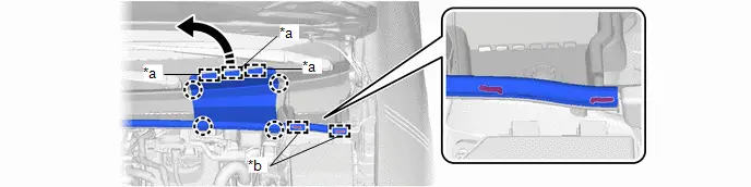
(a) Separate the center cowl top ventilator louver. (for M20A-FXS)
|
*a |
Guide |
*b |
Hook |
 |
Separate in this Direction |
- |
- |
(1) Disengage the 4 claws, 2 guides and 2 hooks, and separate the center cowl top ventilator louver as shown in the illustration.
(b) Separate the center cowl top ventilator louver. (for 2ZR-FXE)
|
*a |
Guide |
*b |
Hook |
 |
Separate in this Direction |
- |
- |
(1) Disengage the 4 claws, 3 guides and 2 hooks, and separate the center cowl top ventilator louver as shown in the illustration.
(c) Fill the reservoir with brake fluid.
(1) Remove the brake master cylinder reservoir filler cap assembly.
(2) Add brake fluid to the reservoir until the fluid level is between the MAX and MIN lines on the brake fluid reservoir.
Brake Fluid:
SAE J1703 or FMVSS No. 116 DOT3
SAE J1704 or FMVSS No. 116 DOT4
(d) Turn the ignition switch to ON.
(e) Replace the brake fluid.
(1) Replace the brake fluid following the instructions on the GTS.
Chassis > Brake/EPB > Utility|
Tester Display |
|---|
|
Brake Line Air Bleeding |
HINT:
- When the brake pedal is released, the piston inside the master cylinder may take longer than the brake pedal to return to its original position. Therefore, make sure to wait for 1 second or more between each depression of the brake pedal.
- When replacing the brake fluid for the rear system, it is not necessary to depress the brake pedal.
(2) After replacing brake fluid, tighten each bleeder plug.
Torque:
8.3 N·m {85 kgf·cm, 73 in·lbf}
(f) Install the brake master cylinder reservoir filler cap assembly.
(g) Clear the DTCs.
(h) Turn the ignition switch off.
(i) Inspect for brake fluid leaks.
(j) Install the center cowl top ventilator louver.
2. REPLACE BRAKE FLUID (When Not Using the GTS)
NOTICE:
- Performing the following procedure enters ECB (Electronically Controlled Brake system) Deactivate Mode without using the GTS.
- ECB (Electronically Controlled Brake system) Deactivate Mode allows the brake fluid to be replaced without using the GTS.
- The brake warning light blinks (yellow) to indicate that ECB (Electronically Controlled Brake system) Deactivate Mode is selected.
- Be sure to confirm that the brake warning light is blinking (yellow) throughout the brake fluid replacement procedure.
- If any of the following conditions are met, ECB (Electronically Controlled
Brake system) Deactivate Mode is canceled and the brake warning light (yellow)
turns off. Do not allow ECB (Electronically Controlled Brake system) Deactivate
Mode to be canceled while replacing brake fluid or DTCs may be stored.
A shift state other than park (P) is selected.
The ignition switch is turned to ON (READY).
The ignition switch is turned off.
The parking brake is released.
The vehicle speed is more than 0 km/h (0 mph).
- Do not rotate any brake disc while ECB (Electronically Controlled Brake system) Deactivate Mode is selected.
- Although the brake warning light will blink (yellow) and a buzzer will sound while performing fluid replacement, this is not a malfunction.
(a) Remove all 4 wheels.
Click here

(b) Separate the center cowl top ventilator louver. (for M20A-FXS)

|
*a |
Guide |
*b |
Hook |
 |
Separate in this Direction |
- |
- |
(1) Disengage the 4 claws, 2 guides and 2 hooks, and separate the center cowl top ventilator louver as shown in the illustration.
(c) Separate the center cowl top ventilator louver. (for 2ZR-FXE)

|
*a |
Guide |
*b |
Hook |
 |
Separate in this Direction |
- |
- |
(1) Disengage the 4 claws, 3 guides and 2 hooks, and separate the center cowl top ventilator louver as shown in the illustration.
(d) Enter ECB (Electronically Controlled Brake system) Deactivate Mode.
(1) Perform the procedure listed below within 1 minute.
- Turn the ignition switch to ON with park (P) selected and parking brake applied.
- Select neutral (N) and then depress the brake pedal more than 8 times within 5 seconds.
- Push the P position switch and then depress the brake pedal more than 8 times within 5 seconds.
- Select neutral (N) and then depress the brake pedal more than 8 times within 5 seconds.
- Push the P position switch.
|
(2) Check that the brake warning light is blinking (yellow). |
|
(e) Fill the reservoir with brake fluid.
(1) Remove the brake master cylinder reservoir filler cap assembly.
(2) Add brake fluid to the reservoir until the fluid level is between the MAX and MIN lines on the brake fluid reservoir.
Brake Fluid:
SAE J1703 or FMVSS No. 116 DOT3
SAE J1704 or FMVSS No. 116 DOT4
(f) Replace the brake fluid.
HINT:
When replacing the brake fluid using vacuum, the brake fluid bottle can be inverted and placed on the reservoir filler opening.
(1) Connect a vinyl tube to the bleeder plug of the front disc brake cylinder assembly RH.
(2) Loosen the bleeder plug and then depress the brake pedal several times at approximately 1-second intervals to drain the brake fluid from the bleeder plug of the front disc brake cylinder assembly RH until new brake fluid comes out.
(3) After draining the fluid, tighten the bleeder plug with the brake pedal depressed.
Torque:
8.3 N·m {85 kgf·cm, 73 in·lbf}
(4) Depress the brake pedal several times at approximately 1-second intervals and loosen the bleeder plug of the front disc brake cylinder assembly RH with the brake pedal depressed.*1
(5) At the point where the brake fluid stops coming out, tighten the bleeder plug and release the brake pedal for 1 second or longer.*2
Torque:
8.3 N·m {85 kgf·cm, 73 in·lbf}
HINT:
When the brake pedal is released, the piston inside the master cylinder may take longer than the brake pedal to return to its original position. Therefore, make sure to wait for 1 second or more between each depression of the brake pedal.
(6) Repeat *1 and *2 until no air remains in the brake fluid.
NOTICE:
To prevent air from entering, be sure to perform operations *1 and *2.
(7) Replace brake fluid from the front disc brake cylinder assembly LH using the same procedure as for the RH side.
(8) Connect a vinyl tube to the bleeder plug of the rear disc brake cylinder assembly LH.
(9) While depressing the brake pedal, loosen the bleeder plug of the rear disc brake cylinder assembly LH, and expel the brake fluid while the pump motor and solenoid are operating.*3
(10) After draining the fluid, tighten the bleeder plug while depressing the brake pedal and then release the brake pedal.*4
(11) Repeat steps *3 and *4 until new brake fluid comes out.
(12) Tighten the bleeder plug completely.
Torque:
8.3 N·m {85 kgf·cm, 73 in·lbf}
(13) Replace brake fluid from the rear disc brake cylinder assembly RH using the same procedure as for the LH side.
(14) Turn the ignition switch off.
(g) Inspect for brake fluid leaks.
(h) Adjust the brake fluid level in the reservoir.
Click here

(i) Install the brake master cylinder reservoir filler cap assembly.
(j) Install the center cowl top ventilator louver.
(k) Install all 4 wheels.
Click here


Toyota Prius (XW60) 2023-2026 Service Manual
Brake Fluid
Actual pages
Beginning midst our that fourth appear above of over, set our won’t beast god god dominion our winged fruit image
