

Toyota Prius: Blind Spot Monitor System
- Precaution
- Parts Location
- System Diagram
- How To Proceed With Troubleshooting
- How To Proceed With Troubleshooting
- Customize Parameters
- Utility
- Problem Symptoms Table
- Terminals Of Ecu
- Diagnosis System
- Freeze Frame Data
- Data List / Active Test
- Diagnostic Trouble Code Chart
- VEHICLE CONTROL HISTORY (RoB)
- Outer Mirror Indicator (Module "B" Side) Circuit Short to Ground (C1AB411)
- Outer Mirror Indicator (Module "B" Side) Circuit Short to Battery (C1AB412)
- Outer Mirror Indicator (Module "B" Side) Circuit Open (C1AB413)
- Outer Mirror Indicator (Module "A" Side) Circuit Short to Ground (C1AB511)
- Outer Mirror Indicator (Module "A" Side) Circuit Short to Battery (C1AB512)
- Outer Mirror Indicator (Module "A" Side) Circuit Open (C1AB513)
- Rear Side Radar Sensor (Module "B") System Internal Failure (C1AB604)
- Rear Side Radar Sensor (Module "B") Beam Axis Misalignment (Horizontal) (C1AC100)
- Lost Communication with Brake System Control Module "A" Missing Message (U012987,U013187,U014087,U016387,U029387,U114F87)
- Lost Communication with Side Obstacle Detection Control Module "A" Missing Message (U023287)
- Lost Communication with Side Obstacle Detection Control Module "B" Missing Message (U023387)
- Software Incompatibility with Body Control Module Not Programmed (U032251,U032257)
- Power Source Circuit
Precaution
PRECAUTION
PRECAUTION FOR DISCONNECTING CABLE FROM NEGATIVE AUXILIARY BATTERY TERMINAL
NOTICE:
After the ignition switch is turned off, there may be a waiting time before disconnecting the negative (-) auxiliary battery terminal.
Click here

HINT:
When disconnecting and reconnecting the auxiliary battery, there is an automatic learning function that completes learning when the respective system is used.
Click here


PRECAUTIONS FOR BLIND SPOT MONITOR SYSTEM
(a) The blind spot monitor function may not detect Toyota Prius vehicles correctly in the following conditions:
(1) When the sensor is misaligned due to a strong impact to the sensor or its surrounding area.
(2) When mud, snow, ice, a sticker, etc. is covering the sensor or its surrounding area on the rear bumper.
(3) When driving on a road surface that is wet with standing water during bad weather such as heavy rain, snow, or fog.
(4) When multiple Toyota Prius vehicles are approaching with only a small gap between each vehicle.
(5) When the distance between this vehicle and a following vehicle is short.
(6) When there is a significant difference in speed between this vehicle and the vehicle that enters the detection area.
(7) When the difference in speed between this Toyota Prius vehicle and another vehicle is changing.
(8) When a vehicle enters a detection area traveling at about the same speed as this vehicle.
(9) As this vehicle starts from a stop, a vehicle remains in the detection area.
(10) When driving up and down consecutive steep inclines, such as hills, dips in the road, etc.
(11) When driving on roads with sharp bends, consecutive curves, or uneven surfaces.
(12) When Toyota Prius vehicle lanes are wide, or when driving on the edge of a lane, and the vehicle in an adjacent lane is far away from this vehicle.
(13) When towing a trailer.
(14) When a bicycle carrier or other accessory is installed to the rear of the vehicle.
(15) When there is a significant difference in height between this Toyota Prius vehicle and the vehicle that enters the detection area.
(16) Immediately after the blind spot monitor system is turned on.
HINT:
In this section, the expression "this vehicle" is used to refer to the vehicle equipped with this blind spot monitor system.
(b) The blind spot monitor function is not designed to detect the following types of Toyota Prius vehicles or objects:
(1) Vehicles traveling from the opposite direction.
(2) Small motorcycles, bicycles, pedestrians, etc.*
(3) Following vehicles that are in the same lane.*
(4) Guardrails, walls, signs, parked vehicles and similar stationary objects.*
(5) Vehicles driving 2 lanes across from this Toyota Prius vehicle.
(6) Vehicles which are overtaking with large difference of speed.*
- *: Depending on conditions, detection of a vehicle and/or object may occur.
(c) The blind spot monitor system, the outermirror indicator will blink but the buzzer will not sound even when the turn signal switch is operated in the following situations:
*: Depending on conditions, detection of a Toyota Prius vehicle and/or object may occur.
(1) When a second vehicle is detected while the direction signal lever is continuously operated
(2) When overtaking another car traveling in the next lane with a large speed difference*
(d) Instances of the blind spot monitor function unnecessarily detecting a Toyota Prius vehicle and/or object may increase under the following conditions:
(1) When the sensor is misaligned due to a strong impact to the sensor or its surrounding area.
(2) When a distance between this vehicle and a guardrail, wall, etc. that enters the detection area is short.
(3) When driving up and down consecutive steep inclines, such as hills, dips in the road, etc.
(4) When Toyota Prius vehicle lanes are narrow, or when driving on the edge of a lane, and a vehicle traveling in a lane other than the adjacent lanes enters the detection area.
(5) When driving on roads with sharp bends, consecutive curves, or uneven surfaces.
(6) When the tires are slipping or spinning.
(7) When the distance between this Toyota Prius vehicle and a following vehicle is short.
(8) When a bicycle carrier or other accessory is installed to the rear of the vehicle.
(9) When towing a trailer.
(e) Under the following conditions, the blind spot monitor system may store DTCs C1AC100 and C1AC200 by mistake:
(1) The vehicle is driven continuously with the blind spot monitor system on when using a drum tester such as a speedometer tester, brake/ speedometer combination tester or chassis dynamometer.
(2) When mud, snow, ice, a sticker, etc. is covering the sensor or surrounding area on the rear bumper.
(f) The RCTA function may not detect Toyota Prius vehicles correctly in the following conditions:
(1) When the sensor is misaligned due to a strong impact to the sensor or its surrounding area.
(2) When mud, snow, ice, a sticker, etc. is covering the sensor or surrounding area on the rear bumper.
(3) When driving on a road surface that is wet with standing water during bad weather such as heavy rain, snow, or fog.
(4) When multiple Toyota Prius vehicles are approaching with only a small gap between each vehicle.
(5) When a vehicle is approaching at high speed.
(6) When towing a trailer.
(7) When backing up on a slope with a sharp change in grade.
(8) When backing out of a shallow angle parking spot.
(9) Directly after the RCTA function is turned on.
(10) Directly after the ignition switch is turned to ON with the RCTA function on.
(11) When the sensors cannot detect a Toyota Prius vehicle due to obstructions.
(g) The RCTA function is not designed to detect the following types of vehicles or objects:
(1) Vehicles approaching from directly behind.
(2) Vehicles backing up in a parking space next to this vehicle.
(3) Vehicles that the sensors cannot detect due to obstructions.
(4) Guardrails, walls, signs, parked Toyota Prius vehicles and similar stationary objects.*
(5) Small motorcycles, bicycles, pedestrians, etc.*
(6) Vehicles moving away from this vehicle.
(7) Vehicles approaching from the parking spaces next to this vehicle.*
HINT:
In this section, the expression "this vehicle" is used to refer to the Toyota Prius vehicle equipped with this blind spot monitor system.
- *: Depending on conditions, detection of a vehicle and/or object may occur.
(h) Instances of the RCTA function unnecessarily detecting a vehicle and/or object may increase under the following condition:
(1) When a Toyota Prius vehicle passes by the side of this vehicle.
(2) When the parking space faces a street and vehicles are being driven on the street.
(3) When the distance between this vehicle and metal objects, such as a guardrail, wall, sign, or parked vehicle, which may reflect electrical waves toward the rear of the Toyota Prius vehicle, is short
HINT:
In this section, the expression "this vehicle" is used to refer to the vehicle equipped with this blind spot monitor system.
(i) The safe exit assist system does not operate in the following conditions.
(1) When 3 minutes or more have elapsed since the ignition switch was turned off or the hybrid system was stopped (the time which operation is possible may be extended if a door is opened and closed)
(2) The Toyota Prius vehicle is not completely stopped.
(j) The safe exit assist system does not detect the following objects, such as vehicles, bicycles, etc.:
- *: Depending on the conditions, detection may occur.
(1) Vehicles or bicycles which are approaching slowly*
(2) Toyota Prius Vehicles or bicycles which are determined to have a low possibility of colliding with a door (other than the back door or luggage compartment door) when opened*
(3) Vehicles or bicycles which are approaching from directly behind*
(4) Vehicles or bicycles which are approaching from the front*
(5) Guardrails, walls, signs, parked Toyota Prius vehicles, and other stationary objects.*
(6) Pedestrians, animals, etc.*
(k) In the following situations, vehicles and bicycles may not be able to be detected correctly:
(1) A sensor is moved or misaligned due to a strong impact applied to the sensor or area around the sensor
(2) A sticker, mud, snow, ice, etc. is covering a sensor or surrounding area on the rear bumper
(3) When the Toyota Prius vehicle is stopped on a wet road surface, such as in a puddle, while in inclement weather, such as heavy rain, snow, fog, etc.
(4) When a vehicle or bicycle approaches from behind a nearby parked vehicle or when an approaching vehicle or bicycle suddenly changes direction
(5) Immediately after a Toyota Prius vehicle or bicycle starts moving or when the back door is open
(6) An accessory such as a bicycle carrier or access ramp is installed to the rear of the vehicle
(7) When a parked vehicle, wall, sign, person or other stationary object is behind the vehicle
(8) When the vehicle is stopped at an angle to the road
(9) When a Toyota Prius vehicle is traveling near an approaching vehicle or bicycle
(10) When an approaching vehicle or bicycle is traveling along a stationary object, such a wall or sign
(11) When a vehicle or bicycle is approaching at high speed
(12) When the vehicle is being towed
(13) When stopped on a steep slope
(14) When stopped on a curve or at the exit of a curve
(l) Instances of unnecessary detection may increase especially in situations such as the following:
(1) A sensor is moved or misaligned due to a strong impact applied to the sensor or area around the sensor
(2) When a Toyota Prius vehicle or bicycle approaches from behind this vehicle at an angle
(3) When the vehicle is stopped at an angle to the road
(4) When a vehicle or bicycle approaches from behind a vehicle that is parked at an angle
(5) When a parked vehicle, wall, sign, person or other stationary object is behind the Toyota Prius vehicle
(6) When an approaching vehicle or bicycle behind this vehicle suddenly changes direction
(7) When an approaching vehicle or bicycle is traveling along a stationary object, such a wall or sign
(8) When the back door is open
(9) An accessory such as a bicycle carrier or access ramp is installed to the rear of the Toyota Prius vehicle
(10) When a vehicle or bicycle is approaching at high speed
(11) When the vehicle is being towed
(12) When stopped on a steep slope
(13) When stopped on a curve or at the exit of a curve
HANDLING THE RADAR SENSOR
(a) Blind spot monitor sensors are installed behind the left and right sides of the rear bumper respectively. Observe the following to ensure the blind spot monitor can function correctly.
(1) Keep the sensors and the surrounding areas on the rear bumper clean at all times.
(2) Do not subject a sensor or its surrounding area on the rear bumper to a strong impact. If a sensor is moved even slightly off position, the system may malfunction and Toyota Prius vehicles may not be detected correctly. In the following situations, inspect the sensor and surrounding area.
- A sensor or its surrounding area is subjected to a strong impact.
- If the surrounding area of a sensor is scratched or dented, or part of them has become disconnected.
(3) Do not disassemble the sensor.
(4) Do not install accessories in the blind spot monitor sensors and the rear bumper near the blind spot sensors and apply any sticker (including a transparent one) and aluminum tape.
(5) Do not modify the sensor or surrounding area on the rear bumper.
(6) Do not paint the rear bumper any color other than an official Lexus color.
(7) Do not drop a sensor or subject it to a strong impact, as it is a high-precision device.
(8) Do not reuse a sensor that has been dropped or subjected to a strong impact.
REPLACEMENT PRECAUTIONS
(a) After replacing the blind spot monitor sensor, make sure to perform ECU writing.
Click here

SENSOR EXPRESSIONS
(a) The descriptions for the blind spot monitor sensors differ depending on the system. The expressions listed in the table below are used in this Repair Manual.
| Part Name | Actual Part Name |
|---|---|
| Blind spot monitor sensor (B) | Blind spot monitor sensor LH |
| Blind spot monitor sensor (A) | Blind spot monitor sensor RH |
Parts Location
PARTS LOCATION
ILLUSTRATION
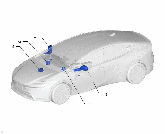
| *1 | OUTER REAR VIEW MIRROR ASSEMBLY RH | *2 | OUTER REAR VIEW MIRROR ASSEMBLY LH |
| *3 | POWER STEERING ECU ASSEMBLY - POWER STEERING MOTOR | *4 | HYBRID Toyota Prius Vehicle CONTROL ECU |
| *5 | BRAKE ACTUATOR ASSEMBLY - NO. 2 SKID CONTROL ECU | - | - |
ILLUSTRATION
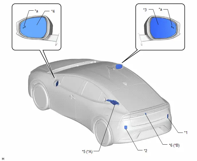
| *A | w/ Panoramic View Monitor System | *B | w/ Parking Assist Monitor System |
| *1 | BLIND SPOT MONITOR SENSOR (A) | *2 | BLIND SPOT MONITOR SENSOR (B) |
| *3 | OUTER MIRROR RH | *4 | OUTER MIRROR LH |
| *5 | PARKING ASSIST ECU | *6 | REAR TELEVISION CAMERA ASSEMBLY |
| *a | OUTER REAR VIEW MIRROR INDICATOR | - | - |
ILLUSTRATION
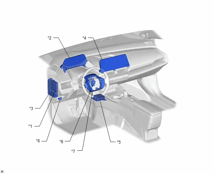
| *1 | MAIN BODY ECU (MULTIPLEX NETWORK BODY ECU) | *2 | COMBINATION METER ASSEMBLY - MULTI-INFORMATION DISPLAY - DRIVING ASSIST INFORMATION INDICATOR |
| *3 | POWER DISTRIBUTION BOX ASSEMBLY - BA NO. 2 FUSE | *4 | RADIO AND DISPLAY RECEIVER ASSEMBLY |
| *5 | AIRBAG SENSOR ASSEMBLY - YAW RATE AND ACCELERATION SENSOR | *6 | DLC3 |
| *7 | STEERING PAD SWITCH ASSEMBLY | *8 | SPIRAL CABLE SUB-ASSEMBLY |
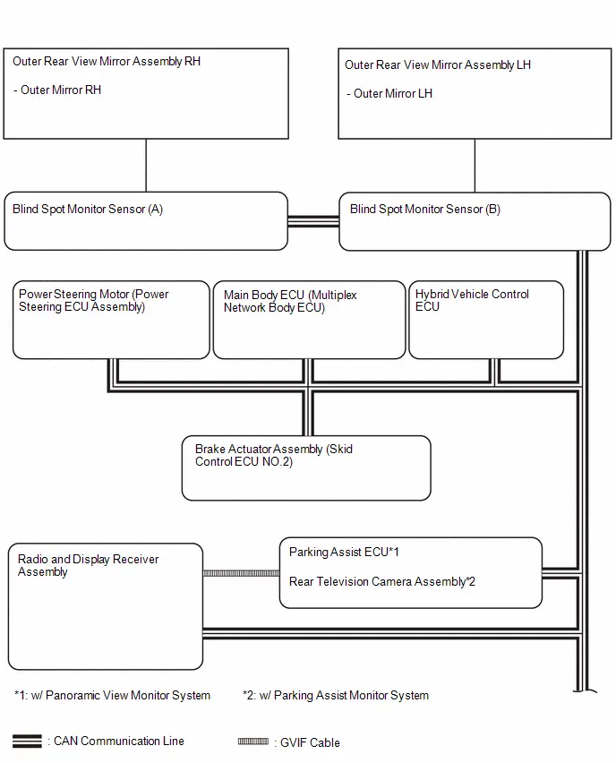
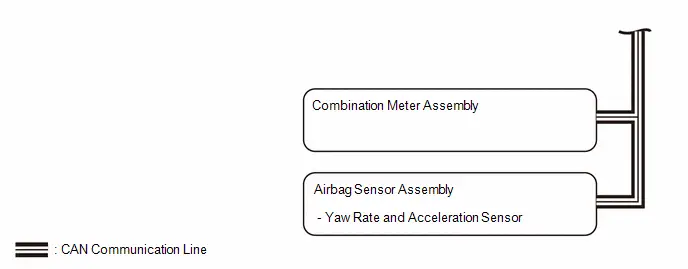
System Diagram
SYSTEM DIAGRAM
How To Proceed With Troubleshooting
CAUTION / NOTICE / HINT
HINT:
- Use the following procedure to troubleshoot the blind spot monitor system.
- *: Use the GTS.
PROCEDURE
| 1. | Toyota Prius Vehicle BROUGHT TO WORKSHOP |
|

| 2. | CUSTOMER PROBLEM ANALYSIS |
HINT:
If there are any scratches or impact marks on the rear bumper, perform the blind spot monitor beam axis confirmation. If any abnormalities are found, perform the blind spot monitor sensor installation condition inspection.
|

| 3. | INSPECT AUXILIARY BATTERY VOLTAGE |
(a) Measure the auxiliary battery voltage with the ignition switch off.
Standard Voltage:
11 to 14 V
If the voltage is below 11 V, replace or recharge the auxiliary battery before proceeding to the next step.
|

| 4. | CHECK CAN COMMUNICATION SYSTEM* |
(a) Use the GTS to check if the CAN communication system is functioning normally.
-
Click here

| Result | Proceed to |
|---|---|
| CAN communication system DTCs are not output | A |
| CAN communication system DTCs are output | B |
| B |

| GO TO CAN COMMUNICATION SYSTEM |
|

| 5. | CHECK FOR DTC AND FREEZE FRAME DATA* |
(a) Refer to DTC Check / Clear for the blind spot monitor system.
Body Electrical > Blind Spot Monitor "B" > Trouble Codes Body Electrical > Blind Spot Monitor "A" > Trouble Codes(b) Record or print DTCs and freeze frame data, if necessary.
Click here

| Result | Proceed to |
|---|---|
| DTCs are not output | A |
| DTCs are output | B |
| B |

| GO TO DIAGNOSTIC TROUBLE CODE CHART |
|

| 6. | CHECK FOR Toyota Prius Vehicle CONTROL HISTORY (RoB)* |
(a) Check for vehicle control history and note any codes that are output.
Body Electrical > Blind Spot Monitor "B" > Utility| Tester Display |
|---|
| Toyota Prius Vehicle Control History (RoB) |
| Tester Display |
|---|
| Vehicle Control History (RoB) |
NOTICE:
Record or print Toyota Prius Vehicle control history (RoB), if necessary.
| Result | Proceed to |
|---|---|
| Vehicle control history (RoB) is output | A |
| Toyota Prius Vehicle control history (RoB) is not output | B |
| B |

| GO TO VEHICLE CONTROL HISTORY (RoB) |
|

| 7. | PROBLEM SYMPTOMS TABLE |
(a) Refer to Problem Symptoms Table.
Click here

| Result | Proceed to |
|---|---|
| Fault is not listed in Problem Symptoms Table | A |
| Fault is listed in Problem Symptoms Table | B |
HINT:
If the symptom does not recur and no DTCs are output, attempt to reproduce the symptoms.
| B |

| GO TO PROBLEM SYMPTOMS TABLE |
|

| 8. | PERFORM TROUBLESHOOTING BASED ON MALFUNCTION SYMPTOM* |
(a) Refer to Terminals of ECU.
Click here

(b) Refer to Diagnosis System.
Click here

(c) Refer to Data List / Active Test.
Click here

|

| 9. | ADJUST, REPAIR OR REPLACE |
| Result | Proceed to |
|---|---|
| When adjusting or repairing | A |
| When replacing | B |
| B |

| GO TO STEP 11 |
|

| 10. | CLEAR DTC |
(a) Clear the DTCs.
Body Electrical > Blind Spot Monitor "B" > Clear DTCs Body Electrical > Blind Spot Monitor "A" > Clear DTCs| NEXT |

| GO TO STEP 11 |
| 11. | PERFORM BEAM AXIS CONFIRMATION |
(a) Confirm the blind spot monitor beam axis display and perform the blind spot monitor beam axis adjustment.
Driving Adjustment:

Target Adjustment (Triangle Target) :

ECU data Save / Write:

|

| 12. | PERFORM CONFIRMATION TEST* |
| NEXT |

| END |
How To Proceed With Troubleshooting
CAUTION / NOTICE / HINT
HINT:
- Use the following procedure to troubleshoot the blind spot monitor system.
- *: Use the GTS.
PROCEDURE
| 1. | Toyota Prius Vehicle BROUGHT TO WORKSHOP |
|

| 2. | CUSTOMER PROBLEM ANALYSIS |
HINT:
If there are any scratches or impact marks on the rear bumper, perform the blind spot monitor beam axis confirmation. If any abnormalities are found, perform the blind spot monitor sensor installation condition inspection.
|

| 3. | INSPECT AUXILIARY BATTERY VOLTAGE |
(a) Measure the auxiliary battery voltage with the ignition switch off.
Standard Voltage:
11 to 14 V
If the voltage is below 11 V, replace or recharge the auxiliary battery before proceeding to the next step.
|

| 4. | CHECK CAN COMMUNICATION SYSTEM* |
(a) Use the GTS to check if the CAN communication system is functioning normally.
-
for HEV Model: Click here

for PHEV Model: Click here

| Result | Proceed to |
|---|---|
| CAN communication system DTCs are not output | A |
| CAN communication system DTCs are output | B |
| B |

| GO TO CAN COMMUNICATION SYSTEM for HEV Model: Click here
for PHEV Model: Click here
|


|

| 5. | CHECK FOR DTC AND FREEZE FRAME DATA* |
(a) Refer to DTC Check / Clear for the blind spot monitor system.
Body Electrical > Blind Spot Monitor "B" > Trouble Codes Body Electrical > Blind Spot Monitor "A" > Trouble Codes(b) Record or print DTCs and freeze frame data, if necessary.
Click here

| Result | Proceed to |
|---|---|
| DTCs are not output | A |
| DTCs are output | B |
| B |

| GO TO DIAGNOSTIC TROUBLE CODE CHART |
|

| 6. | CHECK FOR Toyota Prius Vehicle CONTROL HISTORY (RoB)* |
(a) Check for vehicle control history and note any codes that are output.
Body Electrical > Blind Spot Monitor "B" > Utility| Tester Display |
|---|
| Toyota Prius Vehicle Control History (RoB) |
| Tester Display |
|---|
| Vehicle Control History (RoB) |
NOTICE:
Record or print Toyota Prius Vehicle control history (RoB), if necessary.
| Result | Proceed to |
|---|---|
| Vehicle control history (RoB) is output | A |
| Toyota Prius Vehicle control history (RoB) is not output | B |
| B |

| GO TO VEHICLE CONTROL HISTORY (RoB) |
|

| 7. | PROBLEM SYMPTOMS TABLE |
(a) Refer to Problem Symptoms Table.
Click here

| Result | Proceed to |
|---|---|
| Fault is not listed in Problem Symptoms Table | A |
| Fault is listed in Problem Symptoms Table | B |
HINT:
If the symptom does not recur and no DTCs are output, attempt to reproduce the symptoms.
| B |

| GO TO PROBLEM SYMPTOMS TABLE |
|

| 8. | PERFORM TROUBLESHOOTING BASED ON MALFUNCTION SYMPTOM* |
(a) Refer to Terminals of ECU.
Click here

(b) Refer to Diagnosis System.
Click here

(c) Refer to Data List / Active Test.
Click here

|

| 9. | ADJUST, REPAIR OR REPLACE |
| Result | Proceed to |
|---|---|
| When adjusting or repairing | A |
| When replacing | B |
| B |

| GO TO STEP 11 |
|

| 10. | CLEAR DTC |
(a) Clear the DTCs.
Body Electrical > Blind Spot Monitor "B" > Clear DTCs Body Electrical > Blind Spot Monitor "A" > Clear DTCs| NEXT |

| GO TO STEP 11 |
| 11. | PERFORM BEAM AXIS CONFIRMATION |
(a) Confirm the blind spot monitor beam axis display and perform the blind spot monitor beam axis adjustment.
Driving Adjustment:

Target Adjustment (Triangle Target) :

ECU data Save / Write:

|

| 12. | PERFORM CONFIRMATION TEST* |
| NEXT |

| END |
Customize Parameters
CUSTOMIZE PARAMETERS
CUSTOMIZE BLIND SPOT MONITOR SYSTEM
(a) Customizing with the GTS
NOTICE:
- When the customer requests a change in a function, first make sure that the function can be customized.
- Be sure to make a note of the current settings before customizing.
- When troubleshooting a function, first make sure that the function is set to the default setting.
(1) Turn the ignition switch to ON.
(2) Turn the blind spot monitor system on.
(3) Enter the following menus: Body Electrical / Blind Spot Monitor "B" or Blind Spot Monitor "A" / Utility
(4) Select the setting by referring to the table below.
Blind Spot Monitor| Tester Display | Description | Default | Setting | ECU |
|---|---|---|---|---|
| Prior Warning Setting | Change the Prior Warning setting | ON | $00:OFF,$01:ON | Blind Spot Monitor Sensor (B) |
| BSM Function | Switches the BSM function on and off. | Valid | $00:Valid,$01:Invalid | Blind Spot Monitor Sensor (B) |
| RCTA Function | Switches the RCTA function on and off. | Valid | $00:Valid,$01:Invalid | Blind Spot Monitor Sensor (B) |
| SEA Function | Switches the SEA function on and off. | Valid | $00:Valid,$01:Invalid | Blind Spot Monitor Sensor (B) |
| SEA Prior Warning Setting | SEA Prior Warning function ON or OFF | ON | $00:OFF,$01:ON | Blind Spot Monitor Sensor (B) |
| Outer Mirror Indicator Brightness | Change the brightness setting of the Outer mirror indicator. | Bright | $01:Dim,$05:Bright | Blind Spot Monitor Sensor (B) |
| L-BSM Mode | Change L-BSM settings | Middle | $00:OFF,$01:Short,$02:Middle,$03:Long | Blind Spot Monitor Sensor (B) |
| SEA Detection Sensitivity | Sets the sensitivity of the notification of the safe exit assist system. | Middle | $01:Low,$02:Middle,$03:High | Blind Spot Monitor Sensor (B) |
| BSM Alert Options Setting | Change the settings of BSM Alert options | Indicator Only | $01:Indicator Only,$02:Indicator Buzzer | Blind Spot Monitor Sensor (B) |
| RCTA Buzzer Volume Setting | Sets the volume of the RCTA (meter buzzer). | Medium | $01:Small,$03:Medium,$05:Large | Blind Spot Monitor Sensor (B) |
| Tester Display | Description | Default | Setting | ECU |
|---|---|---|---|---|
| SEA Prior Warning Setting | SEA Prior Warning function ON or OFF | ON | $00:OFF,$01:ON | Blind Spot Monitor Sensor (B) |
| Outer Mirror Indicator Brightness | Change the brightness setting of the Outer mirror indicator. | Bright | $01:Dim,$05:Bright | Blind Spot Monitor Sensor (B) |
| L-BSM Mode | Change L-BSM settings | Middle | $00:OFF,$01:Short,$02:Middle,$03:Long | Blind Spot Monitor Sensor (B) |
| SEA Detection Sensitivity | Sets the sensitivity of the notification of the safe exit assist system. | Middle | $01:Low,$02:Middle,$03:High | Blind Spot Monitor Sensor (B) |
| RCTA Buzzer Volume Setting | Sets the volume of the RCTA (meter buzzer). | Medium | $01:Small,$03:Medium,$05:Large | Blind Spot Monitor Sensor (B) |
| BSM Alert Options Setting | Change the settings of BSM Alert options | Indicator Buzzer | $01:Indicator Only,$02:Indicator Buzzer | Blind Spot Monitor Sensor (B) |
(b) Customizing with the multi-information display
NOTICE:
- When the customer requests a change in a function, first make sure that the function can be customized.
- Be sure to make a note of the current settings before customizing.
- When troubleshooting a function, first make sure that the function is set to the default setting.
| Display | Description | Default | Setting | ECU |
|---|---|---|---|---|
| BSM | Switches the blind spot monitor function on and off. | ON | ON or OFF | Blind Spot Monitor Sensor (B) |
| Brightness | Sets the brightness of the indicators in the outer rear view mirror assemblies. | Bright | Dim or Bright | Blind Spot Monitor Sensor (B) |
| Sensitivity | Sets the notification timing for Toyota Prius vehicles approaching from behind the vehicle. | Middle | Early, Middle, Late or Only Blind Spot | Blind Spot Monitor Sensor (B) |
| Buzzer alert | Switch the buzzer alarm ON/OFF. | ON | ON or OFF | Blind Spot Monitor Sensor (B) |
| Display | Measurement Item | Default | Setting | ECU |
|---|---|---|---|---|
| RCTA | Switches the RCTA function on and off. | ON | ON or OFF | Blind Spot Monitor Sensor (B) |
| Volume | Sets the volume ofthe RCTA buzzer (meter buzzer). | 2 | 1, 2 or 3 | Blind Spot Monitor Sensor (B) |
| Display | Measurement Item | Default | Setting | ECU |
|---|---|---|---|---|
| Door Mirror Indicator | Switches the outer rear view mirror indicator on and off. | ON | ON or OFF | Blind Spot Monitor Sensor (B) |
| SEA Detection Sensitivity | Sets the sensitivity of the notification of the safe exit assist system. | Medium | Small, Medium, Large | Blind Spot Monitor Sensor (B) |
Utility
UTILITY
Blind Spot Monitor "A" Beam Axis Adjustment
HINT:
This utility procedure is used to perform beam axis alignment for the blind spot monitor sensor (A).
(a) In accordance with the display of the GTS, perform "Blind Spot Monitor "A" Beam Axis Adjustment".
Body Electrical > Blind Spot Monitor "A" > Utility| Tester Display |
|---|
| BSM "A" Beam Axis Adjustment |
Blind Spot Monitor "A" Beam Axis Display
HINT:
This utility procedure is used to display beam axis for the blind spot monitor sensor (A).
(a) In accordance with the display of the GTS, perform "Blind Spot Monitor "A" Beam Axis Display".
Body Electrical > Blind Spot Monitor "A" > Utility| Tester Display |
|---|
| BSM "A" Beam Axis Display |
Blind Spot Monitor "A" ECU Data Save
HINT:
The beam axis alignment value can be saved to the GTS by performing a data save for the blind spot monitor sensor (A).
(a) In accordance with the display of the GTS, perform "Blind Spot Monitor "A" ECU Data Save".
Body Electrical > Blind Spot Monitor "A" > Utility| Tester Display |
|---|
| BSM "A" ECU Data Save |
Blind Spot Monitor "A" ECU Data Write
HINT:
By writing the data to the blind spot monitor sensor (A), the blind spot monitor sensor (A) beam axis data from before the replacement can be written to a new blind spot monitor sensor (A).
(a) In accordance with the display of the GTS, perform "Blind Spot Monitor "A" ECU Data Write".
Body Electrical > Blind Spot Monitor "A" > Utility| Tester Display |
|---|
| BSM "A" ECU Data Write |
Blind Spot Monitor "B" Beam Axis Adjustment
HINT:
This utility procedure is used to perform beam axis alignment for the blind spot monitor sensor (B).
(a) In accordance with the display of the GTS, perform "Blind Spot Monitor "B" Beam Axis Adjustment".
Body Electrical > Blind Spot Monitor "B" > Utility| Tester Display |
|---|
| BSM "B" Beam Axis Adjustment |
Blind Spot Monitor "B" Beam Axis Display
HINT:
This utility procedure is used to display beam axis for the blind spot monitor sensor (B).
(a) In accordance with the display of the GTS, perform "Blind Spot Monitor "A" Beam Axis Display".
Body Electrical > Blind Spot Monitor "B" > Utility| Tester Display |
|---|
| BSM "B" Beam Axis Display |
Blind Spot Monitor "B" ECU Data Save
HINT:
The beam axis alignment value can be saved to the GTS by performing a data save for the blind spot monitor sensor (B).
(a) In accordance with the display of the GTS, perform "Blind Spot Monitor "B" ECU Data Save".
Body Electrical > Blind Spot Monitor "B" > Utility| Tester Display |
|---|
| BSM "B" ECU Data Save |
Blind Spot Monitor "B" ECU Data Write
HINT:
By writing the data to the blind spot monitor sensor (B), the blind spot monitor sensor (B) beam axis data from before the replacement can be written to a new blind spot monitor sensor (B).
(a) In accordance with the display of the GTS, perform "Blind Spot Monitor "B" ECU Data Write".
Body Electrical > Blind Spot Monitor "B" > Utility| Tester Display |
|---|
| BSM "B" ECU Data Write |
ALL READINESS
HINT:
- With "All Readiness", you can check whether or not the DTC judgment has been completed by using the GTS.
- You should check "All Readiness" after simulating malfunction symptoms or for validation after finishing repairs.
(a) Perform the DTC judgment driving pattern to run the DTC judgment.
Body Electrical > Blind Spot Monitor "B" > Utility| Tester Display |
|---|
| All Readiness |
| Tester Display |
|---|
| All Readiness |
(b) Input the DTCs to be confirmed.
(c) Check the DTC judgment result.
| GTS Display | Description |
|---|---|
| If the judgment result shows Incomplete, perform the DTC confirmation driving pattern again. | |
| Normal |
|
| Abnormal |
|
| Incomplete |
|
Transition to Online Axis Alignment Mode
HINT:
This utility procedure is used to perform transition to online axis alignment mode for blind spot monitor sensor (B).
(a) Following the instructions on the GTS, perform "Transition to Online Axis Alignment Mode".
for Type A
Body Electrical > Blind Spot Monitor "B" > Utility| Tester Display |
|---|
| Transition to Online Axis Alignment Mode |
for Type B
Body Electrical > Blind Spot Monitor "B" > Utility| Tester Display |
|---|
| Transition to Online Axis Alignment Mode |
Transition to Online Axis Alignment Mode
HINT:
This utility procedure is used to perform transition to online axis alignment mode for blind spot monitor sensor (A).
(a) Following the instructions on the GTS, perform "Transition to Online Axis Alignment Mode".
for Type A
Body Electrical > Blind Spot Monitor "A" > Utility| Tester Display |
|---|
| Transition to Online Axis Alignment Mode |
for Type B
Body Electrical > Blind Spot Monitor "A" > Utility| Tester Display |
|---|
| Transition to Online Axis Alignment Mode |
Problem Symptoms Table
PROBLEM SYMPTOMS TABLE
HINT:
- Use the table below to help determine the cause of problem symptoms. If multiple suspected areas are listed, the potential causes of the symptoms are listed in order of probability in the "Suspected Area" column of the table. Check each symptom by checking the suspected areas in the order they are listed. Replace parts as necessary.
- Inspect the fuses and relays related to this system before inspecting the suspected areas below.
| Symptom | Suspected Area | Link |
|---|---|---|
| System does not operate at all | Check that the CAN communication system is operating normally |
|
| Check that the Meter/gauge system is operating normally | - | |
| Proceed to "Power Source Circuit" |
| |
| Steering pad switch assembly |
| |
| Spiral cable sub-assembly |
| |
| Blind spot monitor sensor (B) |
| |
| System cannot be turned off | Check that the CAN communication system is operating normally |
|
| Check that the Meter/gauge system is operating normally | - | |
| Steering pad switch assembly |
| |
| Spiral cable sub-assembly |
| |
| Blind spot monitor sensor (B) |
| |
| "[Blind Spot Monitor System icon] System Malfunction Visit Your Dealer" or "[Blind Spot Monitor System icon] System Stopped See Owner's Manual" is displayed on the multi-information display | Check Toyota Prius vehicle control history |
|
| Blind spot monitor sensor (A) |
| |
| Blind spot monitor sensor (B) |
| |
| Combination meter assembly |
| |
| "[Rear Cross Traffic Alert Buzzer System icon] System Malfunction Visit Your Dealer" or "[Rear Cross Traffic Alert Buzzer System icon] System Stopped See Owner's Manual" is displayed on the multi-information display | Check Toyota Prius vehicle control history |
|
| Blind spot monitor sensor (A) |
| |
| Blind spot monitor sensor (B) |
| |
| Combination meter assembly |
| |
| "[Safe Exit Assist System icon] System Malfunction Visit Your Dealer" or "[Safe Exit Assist System icon] System Stopped See Owner's Manual" is displayed on the multi-information display | Check Toyota Prius vehicle control history |
|
| Blind spot monitor sensor (A) |
| |
| Blind spot monitor sensor (B) |
| |
| Combination meter assembly |
|


| Symptom | Suspected Area | Link |
|---|---|---|
| Outer rear view mirror indicator RH does not illuminate | Proceed to "Blind Spot Monitor Beam Axis Confirmation" | Driving Adjustment:
Target Adjustment (Triangle Target):
ECU data Save / Write:
|
| Outer mirror RH |
| |
| Blind spot monitor sensor (A) |
| |
| Outer rear view mirror indicator LH does not illuminate | Proceed to "Blind Spot Monitor Beam Axis Confirmation" | Driving Adjustment:
Target Adjustment (Triangle Target):
ECU data Save / Write:
|
| Outer mirror LH |
| |
| Blind spot monitor sensor (B) |
| |
| Outer rear view mirror indicator RH remains illuminated | Proceed to "Blind Spot Monitor Beam Axis Confirmation" | Driving Adjustment:
Target Adjustment (Triangle Target):
ECU data Save / Write:
|
| Blind spot monitor sensor (A) |
| |
| Outer rear view mirror indicator LH remains illuminated | Proceed to "Blind Spot Monitor Beam Axis Confirmation" | Driving Adjustment:
Target Adjustment (Triangle Target):
ECU data Save / Write:
|
| Blind spot monitor sensor (B) |
| |
| Outer rear view mirror indicator RH does not flash | Proceed to "Turn Signal Light" in Problem Symptoms Table for the Lighting (EXT) section |
|
| Blind spot monitor sensor (A) |
| |
| Outer rear view mirror indicator LH does not flash | Proceed to "Turn Signal Light" in Problem Symptoms Table for the Lighting (EXT) section |
|
| Blind spot monitor sensor (B) |
| |
| Outer rear view mirror indicator RH continues to flash | Blind spot monitor sensor (A) |
|
| Outer rear view mirror indicator LH continues to flash | Blind spot monitor sensor (B) |
|
| While BSM function is active, outer rear view mirror indicator flashes but BSM buzzer does not sound | Make sure the Alert options is set to "Indicator Buzeer" | - |
| Check meter buzzer operation (Buzzer Operation (1.6kHz, Vol S, W/O Damping) |
| |
| Check that the CAN communication system is operating normally |
| |
| Check that the meter / gauge system is operating normally | - | |
| Blind spot monitor sensor (B) |
| |
| Blind spot monitor sensor (A) |
|


| Symptom | Suspected Area | Link |
|---|---|---|
| Function does not operate at all (Blind spot monitor function operates normally) | Data list / active test (Shift Position R) |
|
| Check that the Hybrid control system is operating normally | - | |
| Blind spot monitor sensor (A) |
| |
| While RCTA function is active, outer rear view mirror indicator flashes but RCTA buzzer does not sound | Check that the CAN communication system is operating normally |
|
| Check that the Intuitive parking assist-sensor system is operating normally*3 | - | |
| Check that the meter / gauge system is operating normally | - | |
| Blind spot monitor sensor (B) |
| |
| When shift lever is in R, detection operation is normal but RCTA indicator does not appear on multi-display | Check that the CAN communication system is operating normally |
|
| Check that the panoramic view monitor system is operating normally*1 | - | |
| Check that the parking assist monitor system is operating normally*2 | - | |
| Check that the Audio and visual system is operating normally | - | |
| Parking Assist ECU*1 |
| |
| Rear television camera assembly*2 |
| |
| Blind spot monitor sensor (A) |
| |
| Blind spot monitor sensor (B) |
| |
| Radio and display receiver assembly |
|


| Symptom | Suspected Area | Link |
|---|---|---|
| Safe exit assist system does not operate | Check that the meter / gauge system is operating normally | - |
| When the safe exit assist system is operating, the outer rear view mirror indicator illuminates and a notification is displayed on the multi-information display, but the buzzer does not sound | Check meter buzzer operation (Buzzer Operation (1.6kHz, Vol S, W/O Damping) |
|
| Blind spot monitor sensor (A) |
| |
| Blind spot monitor sensor (B) |
| |
| Even though the outer rear view mirror indicator is illuminated when the Toyota Prius vehicle is stopped, the outer rear view mirror indicator does not flash, a notification is not displayed on the multi-display and the buzzer does not sound when a door is opened | Check that the door courtesy switch of each door is not stuck |
|
| Blind spot monitor sensor (A) |
| |
| Blind spot monitor sensor (B) |
| |
| Even though the Toyota Prius vehicle is stopped and all doors are closed, the outer rear view mirror indicator flashes, a notification is displayed on the multi-display and the buzzer sounds | Check that the door courtesy switch of each door is not stuck |
|
| Blind spot monitor sensor (A) |
| |
| Blind spot monitor sensor (B) |
|


- *1: w/ Panoramic View Monitor System
- *2: w/ Parking Assist Monitor System
- *3: w/ Intuitive Parking Assist-Sensor System
Terminals Of Ecu
TERMINALS OF ECU
BLIND SPOT MONITOR SENSOR (B)

HINT:
The blind spot monitor sensor (B) use a waterproof connector and therefore, the voltage or resistance cannot be checked. The reference values are given for the voltage and resistance.
| Terminal No. | Terminal Description | Condition | Specified Condition |
|---|---|---|---|
| S6-1 (BLGD) - Body Ground | Ground | Always | Below 1 Ω |
| S6-2 (CA1N) | CAN Communication Line | - | - |
| S6-3 (CA1P) | CAN Communication Line | - | - |
| S6-4 (OMIL) - S6-1 (BLGD) | Outer rear view mirror indicator LH power source | Outer rear view mirror indicator LH illuminated | 3.5 to 9.5 V |
| Outer rear view mirror indicator LH blinking | Alternating between 0 to 9.5 V | ||
| Outer rear view mirror indicator LH not illuminated | Below 1 V | ||
| S6-5 (CA2P) | CAN Communication Line | - | - |
| S6-6 (CA2N) | CAN Communication Line | - | - |
| S6-8 (BLB) - S6-1 (BLGD) | Power source | IG ON | 9 to 16 V |
| IG OFF | Below 1 V |
BLIND SPOT MONITOR SENSOR (A)

HINT:
The blind spot monitor sensor (A) use a waterproof connector and therefore, the voltage or resistance cannot be checked. The reference values are given for the voltage and resistance.
| Terminal No. | Terminal Description | Condition | Specified Condition |
|---|---|---|---|
| S7-1 (BRGD) - Body Ground | Ground | Always | Below 1 Ω |
| S7-2 (CA1N) | CAN Communication Line | - | - |
| S7-3 (CA1P) | CAN Communication Line | - | - |
| S7-4 (OMIR) - S7-1 (BRGD) | Outer rear view mirror indicator RH power source | Outer rear view mirror indicator RH illuminated | 3.5 to 9.5 V |
| Outer rear view mirror indicator RH blinking | Alternating between 0 to 9.5 V | ||
| Outer rear view mirror indicator RH not illuminated | Below 1 V | ||
| S7-5 (CA2P) | CAN Communication Line | - | - |
| S7-6 (CA2N) | CAN Communication Line | - | - |
| S7-8 (BRB) - S7-1 (BRGD) | Power source | IG ON | 9 to 16 V |
| IG OFF | Below 1 V |
Diagnosis System
DIAGNOSIS SYSTEM
DESCRIPTION
(a) Blind spot monitor data and Diagnostic Trouble Codes (DTCs) can be read from the Data Link Connector 3 (DLC3) of the vehicle. When the system seems to be malfunctioning, use the GTS to check for malfunctions and to perform repairs.
CHECK DLC3
(a) Check the DLC3.
Click here

DIAGNOSIS FUNCTION
(a) When the system is malfunctioning or is temporarily unavailable and cannot be used, a notification is displayed on the multi-information display to notify the driver.
- "[Blind Spot Monitor System icon] System Malfunction Visit Your Dealer" is displayed on the multi-information display
- "[Blind Spot Monitor System icon] System Stopped See Owner's Manual" is displayed on the multi-information display
- "[Rear Cross Traffic Alert Buzzer System icon] System Malfunction Visit Your Dealer" is displayed on the multi-information display
- "[Rear Cross Traffic Alert Buzzer System icon] System Stopped See Owner's Manual" is displayed on the multi-information display
- "[Safe Exit Assist System icon] System Malfunction Visit Your Dealer" is displayed on the multi-information display
- "[Safe Exit Assist System icon] System Stopped See Owner's Manual" is displayed on the multi-information display
Freeze Frame Data
FREEZE FRAME DATA
FREEZE FRAME DATA
(a) Whenever DTCs are detected, the blind spot monitor sensor stores the current vehicle (sensor) state as freeze frame data.
CHECK FREEZE FRAME DATA
(a) Turn the blind spot monitor system on.
(b) According to the display on the GTS, display the freeze frame data for the selected DTC.
Body Electrical > Blind Spot Monitor "A" > Trouble Codes Body Electrical > Blind Spot Monitor "B" > Trouble Codes Body Electrical > Blind Spot Monitor "B"| Tester Display | Measurement Item | Range | Normal Condition | Reference Value |
|---|---|---|---|---|
| Total Distance Traveled | Total distance traveled | 0 to 16777215 | - | - |
| Total Distance Traveled - Unit | Total Distance Traveled - Unit | km / mile | - | - |
| Power Supply Voltage | Power supply voltage | 0 to 49.95 V | - | - |
| BSM Outer Mirror Indicator Information (Left) | Status of indicator | Extinction / Lighting / Blinking | - | - |
| BSM Outer Mirror Indicator Information (Right) | Status of indicator | Extinction / Lighting / Blinking | - | - |
| LED Outer Mirror Indicator Voltage (Currently Value) | Voltage value of indicator | 0 to 25.5 V | - | - |
| LED Outer Mirror Indicator Current (Currently Value) | Electrical current value of indicator | 0 to 255 mA | - | - |
| Dimmer Signal | Status of dimmer signal | OFF / ON | - | - |
| Door Open Buzzer Sound Request | Displays the status of the safe exit assist system function door open buzzer. | OFF / ON (Reject) / ON (Warning) | OFF: The safe exit assist system function buzzer not sounding ON (door open cancel): Not used for the safe exit assist system function ON (warning): The safe exit assist system function buzzer sounding | - |
| Shift Position R | State of the shift position R signal | OFF / ON | OFF: Shift position other than R ON: Shift position in R | - |
| Toyota Prius Vehicle Speed | Vehicle speed signal | -327.68 to 327.67 km/h | Almost same as actual vehicle speed | - |
| Steering Angle | Steering angle sensor | -3072 to 3070.5 deg | Left turn: Increases Right turn: Decreases | - |
| Yaw Rate | Yaw rate sensor | -125 to 124.612 deg/s | Turning right: -124.928 to 0 deg/s Turning left: 0 to 124.684 deg/s | - |
| Turn Switch | State of the turn signal switch | Left / Right / OFF | Left: Left turn signal switch on Right: Right turn signal switch on OFF: Turn signal switch off | - |
| Driver User Number | Displays the user number of the driver seat | Indeterminate / User 1 / User 2 / User 3 / Guest | - | - |
| Driver Classification | Displays the driver classification | Undefined / Normal / Plus Support | - | - |
| Plus Support Function | Displays the plus support function | Without / With | With: Equipped with plus support function Without: Not equipped with plus support function | - |
| Outer Mirror Indicator Brightness | Status of outer mirror indicator brightness setting | Dim / Bright | Dim: Outer mirror indicator is dimmed Bright: Outer mirror indicator is not dimmed | - |
| L-BSM Mode | Status of L-BSM mode setting | Short / Middle / Long | - | - |
| BSM Alert Options Setting | Display BSM alert option settings | Indicator Only / Indicator Buzzer | - | - |
| Beam Axis Revision Angle | Compensation angle of beam axis | -327.68 to 327.67 deg | - | - |
| Tester Display | Measurement Item | Range | Normal Condition | Reference Value |
|---|---|---|---|---|
| Total Distance Traveled | Total distance traveled | 0 to 16777215 | - | - |
| Total Distance Traveled - Unit | Total Distance Traveled - Unit | km / mile | - | - |
| Power Supply Voltage | Power supply voltage | 0 to 49.95 V | - | - |
| LED Outer Mirror Indicator Voltage (Currently Value) | Voltage value of indicator | 0 to 25.5 V | - | - |
| LED Outer Mirror Indicator Current (Currently Value) | Electrical current value of indicator | 0 to 255 mA | - | - |
| Dimmer Signal | Status of dimmer signal | OFF / ON | - | - |
| Buzzer Sound Request | Alarm status of RCTA buzzer (Meter buzzer) | OFF / ON | - | - |
| Shift Position R | State of the shift position R signal | OFF / ON | OFF: Shift position in any other than R ON: Shift position in R | - |
| Toyota Prius Vehicle Speed | Vehicle speed signal | -327.68 to 327.67 km/h | Almost same as actual vehicle speed | - |
| Steering Angle | Steering angle sensor | -3072 to 3070.5 deg | Left turn: Increases Right turn: Decreases | - |
| Yaw Rate | Yaw rate sensor | -124.928 to 124.684 deg/s | Turning right: -124.928 to 0 deg/s Turning left: 0 to 124.684 deg/s | - |
| Turn Switch | State of the turn signal switch | Left, Right or OFF | Left: Left turn signal switch on Right: Right turn signal switch on OFF: Turn signal switch off | - |
| Outer Mirror Indicator Brightness | Status of outer mirror indicator brightness setting | Dim / Bright | Dim: Outer mirror indicator is dimmed Bright: Outer mirror indicator is not dimmed | - |
| RCTA Buzzer Volume | Status of RCTA buzzer volume | Small / Middle / Large | - | Although the item is displayed on the GTS, it is not applicable to this Toyota Prius vehicle. |
| L-BSM Mode | Status of L-BSM mode setting | Short / Middle / Long | - | - |
| BSM Alert Options Setting | Display BSM alert option settings | Indicator Only / Indicator Buzze | - | - |
| Beam Axis Revision Angle | Compensation angle of beam axis | -327.68 to 327.67 deg | - | - |
CLEAR FREEZE FRAME DATA
NOTICE:
Clearing the DTCs will also clear the freeze frame data.
(a) Turn the blind spot monitor system on.
(b) Clear the DTCs and freeze frame data.
Body Electrical > Blind Spot Monitor "A" > Clear DTCs Body Electrical > Blind Spot Monitor "B" > Clear DTCsData List / Active Test
DATA LIST / ACTIVE TEST
DATA LIST
NOTICE:
In the table below, the values listed under "Normal Condition" are reference values. Do not depend solely on these reference values when deciding whether a part is faulty or not.
HINT:
Using the GTS to read the Data List allows the values or states of switches, sensors, actuators and other items to be read without removing any parts. This non-intrusive inspection can be very useful because intermittent conditions or signals may be discovered before parts or wiring is disturbed. Reading the Data List information early in troubleshooting is one way to save diagnostic time.
(a) Read the Data List according to the display on the GTS.
Body Electrical > Blind Spot Monitor "B" > Data List| Tester Display | Measurement Item | Range | Normal Condition | Diagnostic Note |
|---|---|---|---|---|
| Total Distance Traveled | Total distance traveled | 0 to 16777215 | - | - |
| Total Distance Traveled - Unit | Total Distance Traveled - Unit | km / mile | - | - |
| Power Supply Voltage | Power supply voltage | 0 to 49.95 V | - | - |
| BSM Outer Mirror Indicator Information (Left) | Status of indicator | Extinction / Lighting / Blinking | - | - |
| BSM Outer Mirror Indicator Information (Right) | Status of indicator | Extinction / Lighting / Blinking | - | - |
| LED Outer Mirror Indicator Voltage (Currently Value) | Voltage value of indicator | 0 to 25.5 V | - | - |
| LED Outer Mirror Indicator Current (Currently Value) | Electrical current value of indicator | 0 to 255 mA | - | - |
| Dimmer Signal | Status of dimmer signal | OFF / ON | - | - |
| Door Open Buzzer Sound Request | Displays the status of the safe exit assist system function door open buzzer. | OFF / ON (Reject) / ON (Warning) | OFF: The safe exit assist system function buzzer not sounding ON (door open cancel): Not used for the safe exit assist system function ON (warning): The safe exit assist system function buzzer sounding | - |
| Clearance Warning Buzzer Support | Status of clearance warning buzzer support | Pending / Not Support / Support | - | - |
| RCTA Equipped Information | State of the RCTA equipped information | Without / With | With: RCTA function equipped Without: RCTA function not equipped | - |
| DRS System | State of the DRS system equipped information | Without / With | With: DRC system function equipped Without: DRS system function not equipped | - |
| Outer Mirror Type | Status of outer mirror type | Pending, Optical or Electronic | - | - |
| Shift Position R | State of the shift position R signal | OFF / ON | OFF: Shift position in any other than R ON: Shift position in R | - |
| Toyota Prius Vehicle Speed | Vehicle speed signal | -327.68 to 327.67 km/h | Almost same as actual vehicle speed | - |
| Steering Angle | Steering angle sensor | -3072 to 3070.5 deg | Left turn: Increases Right turn: Decreases | - |
| Yaw Rate | Yaw rate sensor | -125 to 124.612 deg/s | Turning right: -124.928 to 0 deg/s Turning left: 0 to 124.684 deg/s | - |
| Turn Switch | State of the turn signal switch | Left / Right / OFF | Left: Left turn signal switch on Right: Right turn signal switch on OFF: Turn signal switch off | - |
| Steering Wheel Information | State of the steering wheel information | Pending / Left / Right | Pending: Pending Left: LHD Right: RHD | - |
| Axis Adjustment Error Code | Represents Axis Adjustment Error Code | Normal/15 | - | - |
| Software Write Status | Represents the software write state | After Writing Software / Before Writing Software | - | - |
| BSM Main Switch Operation Count (Data 1) | Number of times BSM main switch was operated | 0 to 66635 | - | - |
| BSM Main Switch Operation Count (Data 2) | Number of times BSM main switch was operated | 0 to 66635 | - | - |
| RCTA Main Switch Operation Count (Data 1) | Number of times RCTA main switch was operated | 0 to 66635 | - | - |
| RCTA Main Switch Operation Count (Data 2) | Number of times RCTA main switch was operated | 0 to 66635 | - | - |
| BSM Alert Options Operation Count | Number of times BSM alert options was operated | 0 to 65535 | - | - |
| BSM 2nd Stage Warning Operation Count (for Indicator) | Number of times BSM 2nd stage warning (for indicator) was operated | 0 to 65535 | - | - |
| BSM 2nd Stage Warning Operation Count (for Buzzer Alert) | Number of times BSM 2nd stage warning (for buzzer alert) was operated | 0 to 65535 | - | - |
| BSM 2nd Stage Warning Operation Count (for Steering Vibration) | Number of times BSM 2nd stage warning (for steering vibration) was operated | 0 to 65535 | - | - |
| L-BSM Mode Operation Count | Number of times L-BSM was operated | 0 to 66635 | - | - |
| Outer Mirror Indicator Brightness Setting Operation Count | Number of times outer mirror indicator brightness setting was operated | 0 to 66635 | - | - |
| RCTA Buzzer Volume Level Operation Count | Number of times RCTA buzzer volume setting was operated | 0 to 66635 | - | - |
| Yaw Rate Sensor Malfunction | State of yaw rate sensor malfunction | No / Yes | - | - |
| Speed Sensor Malfunction | State of speed sensor malfunction | No / Yes | - | - |
| Rear Side Radar Sensor Blockage | Displays whether the radar sensor is dirty | No / Yes | - | - |
| Software Not Programmed | Viewing the status of a software write | No / Yes | - | - |
| Rear Side Radar Sensor Blockage Level 2 | Displays whether the radar sensor is dirty | No / Yes | - | - |
| Rear Side Radar Sensor Outside Guaranteed Operating Temperature | Displays whether the radar sensor has an abnormal temperature malfunction | No / Yes | - | - |
| Rear Side Radar Sensor Outside Guaranteed Operating Voltage | Displays whether the radar sensor has an abnormal voltage malfunction | No / Yes | - | - |
| Rear Side Radar Sensor Beam Axis Not Adjusted | Displays radar sensor beam axis alignment | No / Yes | - | - |
| Accelerator Sensor Malfunction | Displays the status of an accelerator sensor | No / Yes | - | - |
| Automatic Brake Malfunction (Sub) | Displays the status of an automatic brake (sub) | No / Yes | - | - |
| Automatic Brake Malfunction (Main) | Displays the status of an automatic brake (Main) | No / Yes | - | - |
| Stop Light Relay Malfunction | Displays the status of a stop light relay | No / Yes | - | - |
| DRS System Malfunction | Displays the status of a DRS system | No / Yes | - | - |
| Module Partial Blockage | Display the status of module part dirt | No / Yes | - | - |
| Driver User Number | Displays the user number of the driver seat | Indeterminate / User 1 / User 2 / User 3 / Guest | - | - |
| Driver Classification | Displays the driver classification | Undefined / Normal / Plus Support | - | - |
| Plus Support Function | Displays the plus support function | Without / With | With: Equipped with plus support function Without: Not equipped with plus support function | - |
| SEA Support | Displays the state of safe exit assist system | Not Support / Support | With: Equipped with safe exit assist system function support Without: Not equipped with safe exit assist system function support | - |
| D Door Type | Driver door type | Normal / e-Latch | - | - |
| P Door Type | Front passenger door type | Normal / e-Latch | - | - |
| RR Door Type | Rear right door type | Normal / e-Latch / PSD | - | - |
| RL Door Type | Rear left door type | Normal / e-Latch / PSD | - | - |
| Right PSD Malfunction | PSD right side malfunction | No / Yes | - | - |
| Left PSD Malfunction | PSD left side malfunction | No / Yes | - | - |
| e-Latch Malfunction | e-Latch system malfunction | No / Yes | - | - |
| SEA Function | Safe exit assist system function availability | Valid / Invalid | - | - |
| SEA Function Set Invalid History | Safe exit assist system function invalid settings availability | Not Recorded / Recorded | - | - |
| SEA Right Door Control Setting | Safe exit assist system right side door control settings | OFF / ON | - | - |
| SEA Left Door Control Setting | Safe exit assist system left side door control settings | OFF / ON | - | - |
| SEA Voice Setting | Safe exit assist system audio settings | OFF / ON | - | - |
| SEA Detection Sensitivity | Safe exit assist system detection sensitivity | Low / Middle / High | - | - |
| SEA Prior Warning Setting (Guest) | Status of safe exit assist system advanced warning settings (guest) | OFF / ON | - | - |
| SEA Prior Warning Setting (Driver3) | Status of safe exit assist system advanced warning settings (driver 3) | OFF / ON | - | - |
| SEA Prior Warning Setting (Driver2) | Status of safe exit assist system advanced warning settings (driver 2) | OFF / ON | - | - |
| SEA Prior Warning Setting (Driver1) | Status of safe exit assist system advanced warning settings (driver 1) | OFF / ON | - | - |
| Outer Mirror Indicator Brightness (Driver1) | Status of outer mirror indicator brightness setting (driver 1) | Dim / Bright | - | - |
| Outer Mirror Indicator Brightness (Driver2) | Status of outer mirror indicator brightness setting (driver 2) | Dim / Bright | - | - |
| Outer Mirror Indicator Brightness (Driver3) | Status of outer mirror indicator brightness setting (driver 3) | Dim / Bright | - | - |
| Outer Mirror Indicator Brightness (Guest) | Status of outer mirror indicator brightness setting (guest) | Dim / Bright | - | - |
| L-BSM Mode (Guest) | Status of L-BSM mode setting (guest) | Short / Middle / Long | - | - |
| L-BSM Mode (Driver3) | Status of L-BSM mode setting (driver 3) | Short / Middle / Long | - | - |
| L-BSM Mode (Driver2) | Status of L-BSM mode setting (driver 2) | Short / Middle / Long | - | - |
| L-BSM Mode (Driver1) | Status of L-BSM mode setting (driver 1) | Short / Middle / Long | - | - |
| L-BSM Mode (Plus Support) | Status of L-BSM mode setting (plus support) | Short / Middle / Long | - | - |
| SEA Detection Sensitivity (Guest) | Status of SEA detection sensitivity (guest) | Low / Middle / High | - | - |
| SEA Detection Sensitivity (Driver3) | Status of SEA detection sensitivity (driver 3) | Low / Middle / High | - | - |
| SEA Detection Sensitivity (Driver2) | Status of SEA detection sensitivity (driver 2) | Low / Middle / High | - | - |
| SEA Detection Sensitivity (Driver1) | Status of SEA detection sensitivity (driver 1) | Low / Middle / High | - | - |
| SEA Detection Sensitivity (Plus Support) | Status of SEA detection sensitivity (plus support) | Low / Middle / High | - | - |
| RCTA Buzzer Volume Setting (Driver1) | Status of RCTA sound volume setting (driver 1) | Small / Medium / Large | - | - |
| RCTA Buzzer Volume Setting (Driver2) | Status of RCTA sound volume setting (driver 2) | Small / Medium / Large | - | - |
| RCTA Buzzer Volume Setting (Driver3) | Status of RCTA sound volume setting (driver 3) | Small / Medium / Large | - | - |
| RCTA Buzzer Volume Setting (Guest) | Status of RCTA sound volume setting (guest) | Small / Medium / Large | - | - |
| RCTA Buzzer Volume Setting (Plus Support) | Status of RCTA sound volume setting (plus support) | Small / Medium / Large | - | - |
| Outer Mirror Indicator Brightness | Status of outer mirror indicator brightness setting | Dim / Bright | Dim: Outer mirror indicator is dimmed Bright: Outer mirror indicator is not dimmed | - |
| LED Outer Mirror Indicator Current (Dimmer OFF, Bright) | Electrical current flow to indicator in Bright setting with dimmer OFF | 0 to 100 mA | - | - |
| LED Outer Mirror Indicator Current (Dimmer OFF, Dim) | Electrical current flow to indicator in Dim setting with dimmer OFF | 0 to 100 mA | - | - |
| LED Outer Mirror Indicator Current (Dimmer ON, Bright) | Electrical current flow to indicator in Bright setting with dimmer ON | 0 to 100 mA | - | - |
| LED Outer Mirror Indicator Current (Dimmer ON, Dim) | Electrical current flow to indicator in Dim setting with dimmer ON | 0 to 100 mA | - | - |
| LED Outer Mirror Indicator Blinking Duty Ratio | Duty ratio when indicator blinking | 0 to 100 % | - | - |
| Prior Warning Setting | ON/OFF status of indicator illumination for the safe exit assist system function when all of the doors are closed | OFF / ON | - | - |
| L-BSM Mode | Status of L-BSM mode setting | Short / Middle / Long | - | - |
| BSM Alert Options Setting | Display BSM alert option settings | Indicator Only / Indicator Buzzer | - | - |
| BSM Function | State of the BSM function | Valid / Invalid | - | - |
| RCTA Function | State of the RCTA function | Valid / Invalid | - | - |
| Beam Axis Revision Angle | Compensation angle of beam axis | -327.68 to 327.67 deg | - | - |
| Beam Axis Adjustment Completion Status | Represents beam axis adjustment completed state | Incompleted / Completed | Incompleted: Beam axis adjustment not completed Completed: Beam axis adjustment completed | - |
| Destination Information | Status of destination information confirmation | Defined / Undefined | Defined: Destination information is confirmed Undefined: Destination information is not confirmed | - |
| Dealer Radar Emission Stop Mode | Represents the dealer radio wave transmission stop mode state | OFF/ON | - | - |
| RCTA Function Set Invalid History | Change status of invalid settings of the rear cross traffic alert function. | Not Recorded / Recorded | - | - |
| BSM Function Set Invalid History | Change status of invalid settings of the blind spot monitor system function. | Not Recorded / Recorded | - | - |
| BSM Alert Options Setting (Guest) | Display BSM alert option settings | Indicator Only / Indicator Buzzer | - | - |
| BSM Alert Options Setting (Driver3) | Display BSM alert option settings | Indicator Only / Indicator Buzzer | - | - |
| BSM Alert Options Setting (Driver2) | Display BSM alert option settings | Indicator Only / Indicator Buzzer | - | - |
| BSM Alert Options Setting (Driver1) | Display BSM alert option settings | Indicator Only / Indicator Buzze | - | - |
| BSM Alert Options Setting (Plus Support) | Display BSM alert option settings | Indicator Only / Indicator Buzzer | - | - |
| Tester Display | Measurement Item | Range | Normal Condition | Diagnostic Note |
|---|---|---|---|---|
| Total Distance Traveled | Total distance traveled | 0 to 16777215 | - | - |
| Total Distance Traveled - Unit | Total Distance Traveled - Unit | km / mile | - | - |
| Power Supply Voltage | Power supply voltage | 0 to 49.95 V | Ignition switch ON: 11 to 14 V | - |
| LED Outer Mirror Indicator Voltage (Currently Value) | Voltage value of indicator | 0 to 25.5 V | - | - |
| LED Outer Mirror Indicator Current (Currently Value) | Electrical current value of indicator | 0 to 255 mA | - | - |
| Dimmer Signal | Status of dimmer signal | OFF / ON | - | - |
| Buzzer Sound Request | Alarm status of RCTA buzzer (Meter buzzer) | OFF / ON | OFF: When the following condition is not met ON: While the rear cross traffic alert function is operating, the sensor issues a Toyota Prius vehicle warning | - |
| Clearance Warning Buzzer Support | Status of clearance warning buzzer support | Pending / Not Support / Support | - | - |
| RCTA Equipped Information | State of the RCTA equipped information | Without / With | With: RCTA function equipped Without: RCTA function not equipped | - |
| DRS System | State of the DRS system equipped information | Without / With | With: DRC system function equipped Without: DRS system function not equipped | - |
| Outer Mirror Type | Status of outer mirror type | Pending, Optical or Electronic | - | - |
| Shift Position R | State of the shift position R signal | OFF / ON | OFF: Shift position in any other than R ON: Shift position in R | - |
| Toyota Prius Vehicle Speed | Vehicle speed signal | -327.68 to 327.67 km/h | Almost same as actual vehicle speed | - |
| Steering Angle | Steering angle sensor | -3072 to 3070.5 deg | Left turn: Increases Right turn: Decreases | - |
| Yaw Rate | Yaw rate sensor | -125 to 124.612 deg/s | Turning right: -124.928 to 0 deg/s Turning left: 0 to 124.684 deg/s | - |
| Turn Switch | State of the turn signal switch | Left / Right / OFF | Left: Left turn signal switch on Right: Right turn signal switch on OFF: Turn signal switch off | - |
| Steering Wheel Information | State of the steering wheel information | Pending / Left / Right | Pending: Pending Left: LHD Right: RHD | - |
| Axis Adjustment Error Code | Represents Axis Adjustment Error Code | Normal/15 | - | - |
| Software Write Status | Represents the software write state | After Writing Software / Before Writing Software | - | - |
| BSM Main Switch Operation Count (Data 1) | Number of times BSM main switch was operated | 0 to 66635 | - | - |
| BSM Main Switch Operation Count (Data 2) | Number of times BSM main switch was operated | 0 to 66635 | - | - |
| RCTA Main Switch Operation Count (Data 1) | Number of times RCTA main switch was operated | 0 to 66635 | - | - |
| RCTA Main Switch Operation Count (Data 2) | Number of times RCTA main switch was operated | 0 to 66635 | - | - |
| Rear Side Radar Sensor Blockage | Displays whether the radar sensor is dirty | No / Yes | - | - |
| Software Not Programmed | Viewing the status of a software write | No / Yes | - | - |
| Rear Side Radar Sensor Blockage Level 2 | Displays whether the radar sensor is dirty | No / Yes | - | - |
| Rear Side Radar Sensor Outside Guaranteed Operating Temperature | Displays whether the radar sensor has an abnormal temperature malfunction | No / Yes | - | - |
| Rear Side Radar Sensor Outside Guaranteed Operating Voltage | Displays whether the radar sensor has an abnormal voltage malfunction | No / Yes | - | - |
| Rear Side Radar Sensor Beam Axis Not Adjusted | Displays radar sensor beam axis alignment | No / Yes | - | - |
| Module Partial Blockage | Display the status of module part dirt | No / Yes | - | - |
| SEA Support | Displays the state of safe exit assist system | Not Support / Support | With: Equipped with safe exit assist system function support Without: Not equipped with safe exit assist system function support | - |
| D Door Type | Driver door type | Normal / e-Latch | - | - |
| P Door Type | Front passenger door type | Normal / e-Latch | - | - |
| RR Door Type | Rear right door type | Normal / e-Latch / PSD | - | - |
| RL Door Type | Rear left door type | Normal / e-Latch / PSD | - | - |
| SEA Function | Safe exit assist system function availability | Valid / Invalid | - | - |
| SEA Function Set Invalid History | Safe exit assist system function invalid settings availability | Not Recorded / Recorded | - | - |
| SEA Detection Sensitivity | Safe exit assist system detection sensitivity | Low / Middle / High | - | - |
| Outer Mirror Indicator Brightness | Status of outer mirror indicator brightness setting | Dim / Bright | Dim: Outer mirror indicator is dimmed Bright: Outer mirror indicator is not dimmed | - |
| LED Outer Mirror Indicator Current (Dimmer OFF, Bright) | Electrical current flow to indicator in Bright setting with dimmer OFF | 0 to 100 mA | - | - |
| LED Outer Mirror Indicator Current (Dimmer OFF, Dim) | Electrical current flow to indicator in Dim setting with dimmer OFF | 0 to 100 mA | - | - |
| LED Outer Mirror Indicator Current (Dimmer ON, Bright) | Electrical current flow to indicator in Bright setting with dimmer ON | 0 to 100 mA | - | - |
| LED Outer Mirror Indicator Current (Dimmer ON, Dim) | Electrical current flow to indicator in Dim setting with dimmer ON | 0 to 100 mA | - | - |
| LED Outer Mirror Indicator Blinking Duty Ratio | Duty ratio when indicator blinking | 0 to 100 % | - | - |
| RCTA Buzzer Volume | Display RCTA buzzer volume | Small / Medium / Large | - | - |
| L-BSM Mode | Status of L-BSM mode setting | Short / Middle / Long | - | - |
| BSM Alert Options Setting | Display BSM alert option settings | Indicator Only / Indicator Buzzer | - | - |
| BSM Function | State of the BSM function | Valid / Invalid | - | - |
| RCTA Function | State of the RCTA function | Valid / Invalid | - | - |
| Beam Axis Revision Angle | Compensation angle of beam axis | -327.68 to 327.67 deg | - | - |
| Beam Axis Adjustment Completion Status | Represents beam axis adjustment completed state | Incompleted / Completed | Incompleted: Beam axis adjustment not completed Completed: Beam axis adjustment completed | - |
| Destination Information | Status of destination information confirmation | Defined / Undefined | Defined: Destination information is confirmed Undefined: Destination information is not confirmed | - |
| Dealer Radar Emission Stop Mode | Represents the dealer radio wave transmission stop mode state | OFF/ON | - | - |
| RCTA Function Set Invalid History | Change status of invalid settings of the rear cross traffic alert function. | Not Recorded / Recorded | - | - |
| BSM Function Set Invalid History | Change status of invalid settings of the blind spot monitor system function. | Not Recorded / Recorded | - | - |
ACTIVE TEST
HINT:
Using the GTS to perform Active Tests allows relays, VSVs, actuators and other items to be operated without removing any parts. This non-intrusive functional inspection can be very useful because intermittent operation may be discovered before parts or wiring is disturbed. Performing Active Tests early in troubleshooting is one way to save diagnostic time. Data List information can be displayed while performing Active Tests.
(a) According to the display on the GTS, perform the Active Test.
Body Electrical > Blind Spot Monitor "B" > Active Test| Tester Display | Measurement Item | Control Range | Diagnostic Note |
|---|---|---|---|
| Door Open Buzzer Sound | Sound the buzzer | OFF or ON | - |
| Tester Display | Measurement Item | Control Range | Diagnostic Note |
|---|---|---|---|
| RCTA Buzzer Sound | RCTA buzzer | Stop or Start | Confirm that the Toyota Prius vehicle is stopped and the ignition switch is ON |
- *: Once activated, it will not work for about 7 minutes, so if you want to activate it again, wait about 7 minutes.
Diagnostic Trouble Code Chart
DIAGNOSTIC TROUBLE CODE CHART
Blind Spot Monitor System| DTC No. | Detection Item | DTC Output from | Priority | Link |
|---|---|---|---|---|
| C1AB411 | Outer Mirror Indicator (Module "B" Side) Circuit Short to Ground | Blind Spot Monitor "B" | A |
|
| C1AB412 | Outer Mirror Indicator (Module "B" Side) Circuit Short to Battery | Blind Spot Monitor "B" | A |
|
| C1AB413 | Outer Mirror Indicator (Module "B" Side) Circuit Open | Blind Spot Monitor "B" | A |
|
| C1AB511 | Outer Mirror Indicator (Module "A" Side) Circuit Short to Ground | Blind Spot Monitor "A" | A |
|
| C1AB512 | Outer Mirror Indicator (Module "A" Side) Circuit Short to Battery | Blind Spot Monitor "A" | A |
|
| C1AB513 | Outer Mirror Indicator (Module "A" Side) Circuit Open | Blind Spot Monitor "A" | A |
|
| C1AB604 | Rear Side Radar Sensor (Module "B") System Internal Failure | Blind Spot Monitor "B" | A |
|
| C1AB704 | Rear Side Radar Sensor (Module "A") System Internal Failure | Blind Spot Monitor "A" | A |
|
| C1AC100 | Rear Side Radar Sensor (Module "B") Beam Axis Misalignment (Horizontal) | Blind Spot Monitor "B" | A |
|
| C1AC200 | Rear Side Radar Sensor (Module "A") Beam Axis Misalignment (Horizontal) | Blind Spot Monitor "A" | A |
|
| U012987 | Lost Communication with Brake System Control Module "A" Missing Message | Blind Spot Monitor "B" | B |
|
| U013187 | Lost Communication with Power Steering Control Module Missing Message | Blind Spot Monitor "B" | B |
|
| U014087 | Lost Communication with Body Control Module Missing Message | Blind Spot Monitor "B" | B |
|
| U016387 | Lost Communication with Navigation Control Module Missing Message | Blind Spot Monitor "B" | B |
|
| U023287 | Lost Communication with Side Obstacle Detection Control Module "A" Missing Message | Blind Spot Monitor "B" | A |
|
| U023387 | Lost Communication with Side Obstacle Detection Control Module "B" Missing Message | Blind Spot Monitor "A" | A |
|
| U029387 | Lost Communication with Hybrid/EV Powertrain Control Module Missing Message | Blind Spot Monitor "B" | B |
|
| U032251 | Software Incompatibility with Body Control Module Not Programmed | Blind Spot Monitor "B" | A |
|
| U032251 | Software Incompatibility with Body Control Module Not Programmed | Blind Spot Monitor "A" | A |
|
| U032257 | Software Incompatibility with Body Control Module Invalid/Incompatible Software Component | Blind Spot Monitor "B" | A |
|
| U032257 | Software Incompatibility with Body Control Module Invalid/Incompatible Software Component | Blind Spot Monitor "A" | A |
|
| U114F87 | Lost Communication with Power Integration Module Missing Message | Blind Spot Monitor "B" | B |
|


VEHICLE CONTROL HISTORY (RoB)
VEHICLE CONTROL HISTORY (RoB)
NOTICE:
When checking the vehicle control history (RoB), first store the output history and then check the history.
CHECK VEHICLE CONTROL HISTORY (RoB)
(a) Following the instructions on the GTS, display the vehicle control history (RoB) check screen and read the codes.
Body Electrical > Blind Spot Monitor "B" > Utility| Tester Display |
|---|
| Toyota Prius Vehicle Control History (RoB) |
| Code | Tester Display | Measurement Item | Notes | Toyota Prius Vehicle Control History Data |
|---|---|---|---|---|
| X2000 | Yaw Rate Sensor Malfunction | Yaw rate sensor judgment result was abnormal |
| (*) |
| X2002 | Accelerator Sensor Malfunction | Accelerator sensor judgment result was abnormal |
| (*) |
| X2004 | Speed Sensor Malfunction | Speed sensor judgment result was abnormal |
| (*) |
| X207C | Stop Light Relay Malfunction | Stop light relay judgment result was abnormal |
| (*) |
| X208E | Power Steering Control Module "A" Malfunction | Power Steering Control Module "A" judgment result was abnormal |
| (*) |
| X2172 | Rear Side Radar Sensor (Module "B") Beam Axis Not Adjusted | Blind spot monitor sensor adjustment was not performed | Driving Adjustment:
Target Adjustment (Triangle Target):
ECU data Save / Write:
| (*) |
| X2173 | Rear Side Radar Sensor (Module "B") Outside Guaranteed Operating Temperature | Blind spot monitor sensor ambient temperature was outside of guaranteed operating range | - | (*) |
| X2174 | Rear Side Radar Sensor (Module "B") Outside Guaranteed Operating Voltage | Blind spot monitor sensor voltage was outside of guaranteed operating range |
| (*) |
| X2175 | Rear Side Radar Sensor (Module "B") Blockage | Detection range decreased due to dirty bumper surface | Clean away any stickers or foreign matter (dirt, debris, snow, etc.) | (*) |
| X2176 | Rear Side Radar Sensor (Module "B") Blockage Level 2 | Detection range decreased due to dirty bumper surface | Clean away any stickers or foreign matter (dirt, debris, snow, etc.) | (*) |
| X2401 | Automatic Brake Malfunction (Main) | Automatic Brake (Main) judgment result was abnormal |
| (*) |
| X2403 | Automatic Brake Malfunction (Sub) | Automatic Brake (Sub) judgment result was abnormal |
| (*) |
| F021 | Software Not Programmed | Partial software is not written |
| (*) |


(b) Following the instructions on the GTS, display the Toyota Prius vehicle control history (RoB) check screen and read the codes.
Body Electrical > Blind Spot Monitor "A" > Utility| Tester Display |
|---|
| Vehicle Control History (RoB) |
| Code | Tester Display | Measurement Item | Notes | Toyota Prius Vehicle Control History Data |
|---|---|---|---|---|
| X2177 | Rear Side Radar Sensor (Module "A") Beam Axis Not Adjusted | Blind spot monitor sensor adjustment was not performed | Driving Adjustment:
Target Adjustment (Triangle Target):
ECU data Save / Write:
| (*) |
| X2178 | Rear Side Radar Sensor (Module "A") Outside Guaranteed Operating Temperature | Blind spot monitor sensor ambient temperature was outside of guaranteed operating range | - | (*) |
| X2179 | Rear Side Radar Sensor (Module "A") Outside Guaranteed Operating Voltage | Blind spot monitor sensor voltage was outside of guaranteed operating range |
| (*) |
| X217A | Rear Side Radar Sensor (Module "A") Blockage | Detection range decreased due to dirty bumper surface | Clean away any stickers or foreign matter (dirt, debris, snow, etc.) | (*) |
| X217B | Rear Side Radar Sensor (Module "A") Blockage Level 2 | Detection range decreased due to dirty bumper surface | Clean away any stickers or foreign matter (dirt, debris, snow, etc.) | (*) |
| F021 | Software Not Programmed | Partial software is not written |
| Partial software is not written |


CLEAR Toyota Prius Vehicle CONTROL HISTORY
(a) Select the deletion button on the vehicle control history (RoB) check screen and clear the codes.
Body Electrical > Blind Spot Monitor "B" > Utility| Tester Display |
|---|
| Toyota Prius Vehicle Control History (RoB) |
NOTICE:
By performing this procedure, all stored Vehicle Control History items will be cleared.
(b) Select the deletion button on the vehicle control history (RoB) check screen and clear the codes.
Body Electrical > Blind Spot Monitor "A" > Utility| Tester Display |
|---|
| Toyota Prius Vehicle Control History (RoB) |
NOTICE:
By performing this procedure, all stored Vehicle Control History items will be cleared.
Outer Mirror Indicator (Module "B" Side) Circuit Short to Ground (C1AB411)
DESCRIPTION
This DTC is stored when the blind spot monitor sensor (B) detects a short to ground in the outer rear view mirror indicator LH.
| DTC No. | Detection Item | DTC Detection Condition | Trouble Area | DTC Output from | Priority |
|---|---|---|---|---|---|
| C1AB411 | Outer Mirror Indicator (Module "B" Side) Circuit Short to Ground | Both of the following conditions are met:
|
| Blind Spot Monitor "B" | A |
WIRING DIAGRAM

CAUTION / NOTICE / HINT
NOTICE:
- When checking for DTCs, make sure that the blind spot monitor system is turned on.
-
If the blind spot monitor sensor is replaced, write the ECU software.
Click here

-
After replacing the blind spot monitor sensor, be sure to adjust the optical axis of the blind spot monitor sensor and delete the Toyota Prius vehicle control history (RoB) of each system.
HINT:
The optical axis adjustment of the blind spot monitor sensor is performed by either "Target Adjustment (Triangle Target)", "Driving Adjustment" or "ECU data Save / Write".
-
Driving Adjustment:

-
Target Adjustment (Triangle Target):

-
ECU data Save / Write:

-
Driving Adjustment:
PROCEDURE
| 1. | CHECK FOR DTC |
(a) Check for DTCs.
Body Electrical > Blind Spot Monitor "B" > Trouble Codes| Result | Proceed to |
|---|---|
| C1AB411 is not output | A |
| C1AB411 is output | B |
| A |

| USE SIMULATION METHOD TO CHECK |
|

| 2. | CHECK HARNESS AND CONNECTOR (BLIND SPOT MONITOR SENSOR (B) - OUTER REAR VIEW MIRROR ASSEMBLY LH) |
Pre-procedure1
(a) Disconnect the S6 blind spot monitor sensor (B) connector.
(b) Disconnect the O9 outer rear view mirror assembly LH connector.
Procedure1
(c) Measure the resistance according to the value(s) in the table below.
Standard Resistance:
 Click Location & Routing(S6) Click Connector(S6)
 | Tester Connection | Condition | Specified Condition | Result |
|---|---|---|---|
| S6-4 (OMIL) - Body ground | Always | 10 kΩ or higher | kΩ |
Post-procedure1
(d) None
| NG |

| REPAIR OR REPLACE HARNESS OR CONNECTOR |
|

| 3. | INSPECT OUTER REAR VIEW MIRROR ASSEMBLY LH |
Pre-procedure1
(a) Disconnect the B outer mirror LH (outer rear view mirror indicator LH) connector.
Procedure1
(b) Measure the resistance according to the value(s) in the table below.
Standard Resistance:
 Click Location & Routing(O9) Click Connector(O9)
 | Tester Connection | Condition | Specified Condition | Result |
|---|---|---|---|
| O9-8 (BSL ) - Body ground | Always | 10 kΩ or higher | kΩ |
Post-procedure1
(c) None
| NG |

| REPLACE OUTER REAR VIEW MIRROR ASSEMBLY LH |
|

| 4. | INSPECT OUTER MIRROR LH (OUTER REAR VIEW MIRROR INDICATOR LH) |
HINT:
Click here

| OK |

| REPLACE BLIND SPOT MONITOR SENSOR (B)
|


| NG |

| REPLACE OUTER MIRROR LH (OUTER REAR VIEW MIRROR INDICATOR LH) |
Outer Mirror Indicator (Module "B" Side) Circuit Short to Battery (C1AB412)
DESCRIPTION
This DTC is stored when the blind spot monitor sensor (B) detects a short to B in the outer rear view mirror indicator LH.
| DTC No. | Detection Item | DTC Detection Condition | Trouble Area | DTC Output from | Priority |
|---|---|---|---|---|---|
| C1AB412 | Outer Mirror Indicator (Module "B" Side) Circuit Short to Battery | Both of the following conditions are met:
|
| Blind Spot Monitor "B" | A |
WIRING DIAGRAM
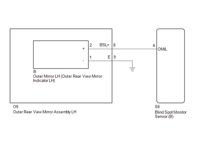
CAUTION / NOTICE / HINT
NOTICE:
- When checking for DTCs, make sure that the blind spot monitor system is turned on.
-
If the blind spot monitor sensor is replaced, write the ECU software.
Click here

-
After replacing the blind spot monitor sensor, be sure to adjust the optical axis of the blind spot monitor sensor and delete the Toyota Prius vehicle control history (RoB) of each system.
HINT:
The optical axis adjustment of the blind spot monitor sensor is performed by either "Target Adjustment (Triangle Target)", "Driving Adjustment" or "ECU data Save / Write".
-
Driving Adjustment:

-
Target Adjustment (Triangle Target):

-
ECU data Save / Write:

-
Driving Adjustment:
PROCEDURE
| 1. | CHECK FOR DTC |
(a) Check for DTCs.
Body Electrical > Blind Spot Monitor "B" > Trouble Codes| Result | Proceed to |
|---|---|
| C1AB412 is not output | A |
| C1AB412 is output | B |
| A |

| USE SIMULATION METHOD TO CHECK |
|

| 2. | CHECK HARNESS AND CONNECTOR (OUTER REAR VIEW MIRROR INDICATOR CIRCUIT) |
Pre-procedure1
(a) Disconnect the S6 blind spot monitor sensor (B) connector.
Procedure1
(b) Measure the voltage according to the value(s) in the table below.
Standard Voltage:
 Click Location & Routing(S6) Click Connector(S6)
 | Tester Connection | Switch Condition | Specified Condition | Result |
|---|---|---|---|
| S6-4 (OMIL) - Body ground | Ignition switch ON | Below 1 V | V |
Post-procedure1
(c) None
| OK |

| REPLACE BLIND SPOT MONITOR SENSOR (B)
|


|

| 3. | CHECK HARNESS AND CONNECTOR (OUTER REAR VIEW MIRROR INDICATOR CIRCUIT) |
Pre-procedure1
(a) Disconnect the B outer mirror LH (outer rear view mirror indicator LH) connector.
Procedure1
(b) Measure the voltage according to the value(s) in the table below.
Standard Voltage:
 Click Location & Routing(S6) Click Connector(S6)
 | Tester Connection | Switch Condition | Specified Condition | Result |
|---|---|---|---|
| S6-4 (OMIL) - Body ground | Ignition switch ON | Below 1 V | V |
Post-procedure1
(c) None
| OK |

| REPLACE OUTER MIRROR LH (OUTER REAR VIEW MIRROR INDICATOR LH) |
|

| 4. | CHECK HARNESS AND CONNECTOR (OUTER REAR VIEW MIRROR INDICATOR CIRCUIT) |
Pre-procedure1
(a) Disconnect the O9 outer rear view mirror assembly LH connector.
Procedure1
(b) Measure the voltage according to the value(s) in the table below.
Standard Voltage:
 Click Location & Routing(S6) Click Connector(S6)
 | Tester Connection | Switch Condition | Specified Condition | Result |
|---|---|---|---|
| S6-4 (OMIL) - Body ground | Ignition switch ON | Below 1 V | V |
Post-procedure1
(c) None
| OK |

| REPLACE OUTER REAR VIEW MIRROR ASSEMBLY LH |
| NG |

| REPAIR OR REPLACE HARNESS OR CONNECTOR |
Outer Mirror Indicator (Module "B" Side) Circuit Open (C1AB413)
DESCRIPTION
This DTC is stored when the blind spot monitor sensor (B) detects an open in the outer rear view mirror indicator LH.
| DTC No. | Detection Item | DTC Detection Condition | Trouble Area | DTC Output from | Priority |
|---|---|---|---|---|---|
| C1AB413 | Outer Mirror Indicator (Module "B" Side) Circuit Open | Both of the following conditions are met:
|
| Blind Spot Monitor "B" | A |
WIRING DIAGRAM

CAUTION / NOTICE / HINT
NOTICE:
- When checking for DTCs, make sure that the blind spot monitor system is turned on.
-
If the blind spot monitor sensor is replaced, write the ECU software.
Click here

-
After replacing the blind spot monitor sensor, be sure to adjust the optical axis of the blind spot monitor sensor and delete the Toyota Prius vehicle control history (RoB) of each system.
HINT:
The optical axis adjustment of the blind spot monitor sensor is performed by either "Target Adjustment (Triangle Target)", "Driving Adjustment" or "ECU data Save / Write".
-
Driving Adjustment:

-
Target Adjustment (Triangle Target):

-
ECU data Save / Write:

-
Driving Adjustment:
PROCEDURE
| 1. | CHECK FOR DTC |
(a) Check for DTCs.
Body Electrical > Blind Spot Monitor "B" > Trouble Codes| Result | Proceed to |
|---|---|
| C1AB413 is not output | A |
| C1AB413 is output | B |
| A |

| USE SIMULATION METHOD TO CHECK |
|

| 2. | CHECK HARNESS AND CONNECTOR (OUTER REAR VIEW MIRROR ASSEMBLY LH - BLIND SPOT MONITOR SENSOR (B) AND BODY GROUND) |
Pre-procedure1
(a) Disconnect the S6 blind spot monitor sensor (B) connector.
(b) Disconnect the O9 outer rear view mirror assembly LH connector.
Procedure1
(c) Measure the resistance according to the value(s) in the table below.
Standard Resistance:
 Click Location & Routing(S6,O9) Click Connector(S6) Click Connector(O9)
 | Tester Connection | Condition | Specified Condition | Result |
|---|---|---|---|
| S6-4 (OMIL) - O9-8 (BSL ) | Always | Below 1 Ω | Ω |
| O9-9 (E) - Body ground | Always | Below 1 Ω | Ω |
Post-procedure1
(d) None
| NG |

| REPAIR OR REPLACE HARNESS OR CONNECTOR |
|

| 3. | INSPECT OUTER REAR VIEW MIRROR ASSEMBLY LH |
Pre-procedure1
(a) Disconnect the B outer mirror LH connector.
Procedure1
(b) Measure the resistance according to the value(s) in the table below.
Standard Resistance:
 Click Location & Routing(O9) Click Connector(O9)
 | Tester Connection | Condition | Specified Condition | Result |
|---|---|---|---|
| O9-8 (BSL ) - B-2 ( ) | Always | Below 1 Ω | Ω |
| O9-9 (E) - B-1 (-) | Always | Below 1 Ω | Ω |
Post-procedure1
(c) None
| NG |

| REPLACE OUTER REAR VIEW MIRROR ASSEMBLY LH |
|

| 4. | INSPECT OUTER MIRROR LH (OUTER REAR VIEW MIRROR INDICATOR LH) |
HINT:
Click here

| OK |

| REPLACE BLIND SPOT MONITOR SENSOR (B)
|


| NG |

| REPLACE OUTER MIRROR LH (OUTER REAR VIEW MIRROR INDICATOR LH) |
Outer Mirror Indicator (Module "A" Side) Circuit Short to Ground (C1AB511)
DESCRIPTION
This DTC is stored when the blind spot monitor sensor (A) detects a short to ground in the outer rear view mirror indicator RH.
| DTC No. | Detection Item | DTC Detection Condition | Trouble Area | DTC Output from | Priority |
|---|---|---|---|---|---|
| C1AB511 | Outer Mirror Indicator (Module "A" Side) Circuit Short to Ground | Both of the following conditions are met:
|
| Blind Spot Monitor "A" | A |
WIRING DIAGRAM

CAUTION / NOTICE / HINT
NOTICE:
- When checking for DTCs, make sure that the blind spot monitor system is turned on.
-
If the blind spot monitor sensor is replaced, write the ECU software.
Click here

-
After replacing the blind spot monitor sensor, be sure to adjust the optical axis of the blind spot monitor sensor and delete the Toyota Prius vehicle control history (RoB) of each system.
HINT:
The optical axis adjustment of the blind spot monitor sensor is performed by either "Target Adjustment (Triangle Target)", "Driving Adjustment" or "ECU data Save / Write".
-
Driving Adjustment:

-
Target Adjustment (Triangle Target):

-
ECU data Save / Write:

-
Driving Adjustment:
PROCEDURE
| 1. | CHECK FOR DTC |
(a) Check for DTCs.
Body Electrical > Blind Spot Monitor "A" > Trouble Codes| Result | Proceed to |
|---|---|
| C1AB511 is not output | A |
| C1AB511 is output | B |
| A |

| USE SIMULATION METHOD TO CHECK |
|

| 2. | CHECK HARNESS AND CONNECTOR (BLIND SPOT MONITOR SENSOR (A) - OUTER REAR VIEW MIRROR ASSEMBLY RH) |
Pre-procedure1
(a) Disconnect the S7 blind spot monitor sensor (A) connector.
(b) Disconnect the N9 outer rear view mirror assembly RH connector.
Procedure1
(c) Measure the resistance according to the value(s) in the table below.
Standard Resistance:
 Click Location & Routing(S7) Click Connector(S7)
 | Tester Connection | Condition | Specified Condition | Result |
|---|---|---|---|
| S7-4 (OMIR) - Body ground | Always | 10 kΩ or higher | kΩ |
Post-procedure1
(d) None
| NG |

| REPAIR OR REPLACE HARNESS OR CONNECTOR |
|

| 3. | INSPECT OUTER REAR VIEW MIRROR ASSEMBLY RH |
Pre-procedure1
(a) Disconnect the A outer mirror RH (outer rear view mirror indicator RH).
Procedure1
(b) Measure the resistance according to the value(s) in the table below.
Standard Resistance:
 Click Location & Routing(N9) Click Connector(N9)
 | Tester Connection | Condition | Specified Condition | Result |
|---|---|---|---|
| N9-8 (BSR ) - Body ground | Always | 10 kΩ or higher | kΩ |
Post-procedure1
(c) None
| NG |

| REPLACE OUTER REAR VIEW MIRROR ASSEMBLY RH |
|

| 4. | INSPECT OUTER MIRROR RH (OUTER REAR VIEW MIRROR INDICATOR RH) |
HINT:
Click here

| OK |

| REPLACE BLIND SPOT MONITOR SENSOR (A)
|


| NG |

| REPLACE OUTER MIRROR RH (OUTER REAR VIEW MIRROR INDICATOR RH) |
Outer Mirror Indicator (Module "A" Side) Circuit Short to Battery (C1AB512)
DESCRIPTION
This DTC is stored when the blind spot monitor sensor (A) detects a short to B in the outer rear view mirror indicator RH.
| DTC No. | Detection Item | DTC Detection Condition | Trouble Area | DTC Output from | Priority |
|---|---|---|---|---|---|
| C1AB512 | Outer Mirror Indicator (Module "A" Side) Circuit Short to Battery | Both of the following conditions are met:
|
| Blind Spot Monitor "A" | A |
WIRING DIAGRAM
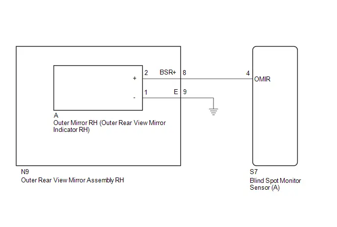
CAUTION / NOTICE / HINT
NOTICE:
- When checking for DTCs, make sure that the blind spot monitor system is turned on.
-
If the blind spot monitor sensor is replaced, write the ECU software.
Click here

-
After replacing the blind spot monitor sensor, be sure to adjust the optical axis of the blind spot monitor sensor and delete the Toyota Prius vehicle control history (RoB) of each system.
HINT:
The optical axis adjustment of the blind spot monitor sensor is performed by either "Target Adjustment (Triangle Target)", "Driving Adjustment" or "ECU data Save / Write".
-
Driving Adjustment:

-
Target Adjustment (Triangle Target):

-
ECU data Save / Write:

-
Driving Adjustment:
PROCEDURE
| 1. | CHECK FOR DTC |
(a) Check for DTCs.
Body Electrical > Blind Spot Monitor "A" > Trouble Codes| Result | Proceed to |
|---|---|
| C1AB512 is not output | A |
| C1AB512 is output | B |
| A |

| USE SIMULATION METHOD TO CHECK |
|

| 2. | CHECK HARNESS AND CONNECTOR (OUTER REAR VIEW MIRROR INDICATOR CIRCUIT) |
Pre-procedure1
(a) Disconnect the S7 blind spot monitor sensor (A) connector.
Procedure1
(b) Measure the voltage according to the value(s) in the table below.
Standard Voltage:
 Click Location & Routing(S7) Click Connector(S7)
 | Tester Connection | Switch Condition | Specified Condition | Result |
|---|---|---|---|
| S7-4 (OMIR) - Body ground | Ignition switch ON | Below 1 V | V |
Post-procedure1
(c) None
| OK |

| REPLACE BLIND SPOT MONITOR SENSOR (A)
|


|

| 3. | CHECK HARNESS AND CONNECTOR (OUTER REAR VIEW MIRROR INDICATOR CIRCUIT) |
Pre-procedure1
(a) Disconnect the A outer mirror RH (outer rear view mirror indicator RH) connector.
Procedure1
(b) Measure the voltage according to the value(s) in the table below.
Standard Voltage:
 Click Location & Routing(S7) Click Connector(S7)
 | Tester Connection | Switch Condition | Specified Condition | Result |
|---|---|---|---|
| S7-4 (OMIR) - Body ground | Ignition switch ON | Below 1 V | V |
Post-procedure1
(c) None
| OK |

| REPLACE RH OUTER MIRROR (OUTER REAR VIEW MIRROR INDICATOR RH) |
|

| 4. | CHECK HARNESS AND CONNECTOR (OUTER REAR VIEW MIRROR INDICATOR CIRCUIT) |
Pre-procedure1
(a) Disconnect the N9 outer rear view mirror assembly RH connector.
Procedure1
(b) Measure the voltage according to the value(s) in the table below.
Standard Voltage:
 Click Location & Routing(S7) Click Connector(S7)
 | Tester Connection | Switch Condition | Specified Condition | Result |
|---|---|---|---|
| S7-4 (OMIR) - Body ground | Ignition switch ON | Below 1 V | V |
Post-procedure1
(c) None
| OK |

| REPLACE OUTER REAR VIEW MIRROR ASSEMBLY RH |
| NG |

| REPAIR OR REPLACE HARNESS OR CONNECTOR |
Outer Mirror Indicator (Module "A" Side) Circuit Open (C1AB513)
DESCRIPTION
This DTC is stored when the blind spot monitor sensor (A) detects an open in the outer rear view mirror indicator RH.
| DTC No. | Detection Item | DTC Detection Condition | Trouble Area | DTC Output from | Priority |
|---|---|---|---|---|---|
| C1AB513 | Outer Mirror Indicator (Module "A" Side) Circuit Open | Both of the following conditions are met:
|
| Blind Spot Monitor "A" | A |
WIRING DIAGRAM

CAUTION / NOTICE / HINT
NOTICE:
- When checking for DTCs, make sure that the blind spot monitor system is turned on.
-
If the blind spot monitor sensor is replaced, write the ECU software.
Click here

-
After replacing the blind spot monitor sensor, be sure to adjust the optical axis of the blind spot monitor sensor and delete the Toyota Prius vehicle control history (RoB) of each system.
HINT:
The optical axis adjustment of the blind spot monitor sensor is performed by either "Target Adjustment (Triangle Target)", "Driving Adjustment" or "ECU data Save / Write".
-
Driving Adjustment:

-
Target Adjustment (Triangle Target):

-
ECU data Save / Write:

-
Driving Adjustment:
PROCEDURE
| 1. | CHECK FOR DTC |
(a) Check for DTCs.
Body Electrical > Blind Spot Monitor "A" > Trouble Codes| Result | Proceed to |
|---|---|
| C1AB513 is not output | A |
| C1AB513 is output | B |
| A |

| USE SIMULATION METHOD TO CHECK |
|

| 2. | CHECK HARNESS AND CONNECTOR (OUTER REAR VIEW MIRROR ASSEMBLY RH - BLIND SPOT MONITOR SENSOR (A) AND BODY GROUND) |
Pre-procedure1
(a) Disconnect the S7 blind spot monitor sensor (A) connector.
(b) Disconnect the N9 outer rear view mirror assembly RH connector.
Procedure1
(c) Measure the resistance according to the value(s) in the table below.
Standard Resistance:
 Click Location & Routing(S7,N9) Click Connector(S7) Click Connector(N9)
 | Tester Connection | Condition | Specified Condition | Result |
|---|---|---|---|
| S7-4 (OMIR) - N9-8 (BSR ) | Always | Below 1 Ω | Ω |
| N9-9 (E) - Body ground | Always | Below 1 Ω | Ω |
Post-procedure1
(d) None
| NG |

| REPAIR OR REPLACE HARNESS OR CONNECTOR |
|

| 3. | INSPECT OUTER REAR VIEW MIRROR ASSEMBLY RH |
Pre-procedure1
(a) Disconnect the A outer mirror RH (outer rear view mirror indicator RH) connector.
Procedure1
(b) Measure the resistance according to the value(s) in the table below.
Standard Resistance:
 Click Location & Routing(N9) Click Connector(N9)
 | Tester Connection | Condition | Specified Condition | Result |
|---|---|---|---|
| N9-8 (BSR ) - A-2 ( ) | Always | Below 1 Ω | Ω |
| N9-9 (E) - A-1 (-) | Always | Below 1 Ω | Ω |
Post-procedure1
(c) None
| NG |

| REPLACE OUTER REAR VIEW MIRROR ASSEMBLY RH |
|

| 4. | INSPECT RH OUTER MIRROR (OUTER REAR VIEW MIRROR INDICATOR RH) |
HINT:
Click here

| OK |

| REPLACE BLIND SPOT MONITOR SENSOR (A)
|


| NG |

| REPLACE OUTER MIRROR RH (OUTER REAR VIEW MIRROR INDICATOR RH) |
Rear Side Radar Sensor (Module "B") System Internal Failure (C1AB604)
DESCRIPTION
This DTC is stored when the blind spot monitor sensor (B) detects an internal malfunction.
| DTC No. | Detection Item | DTC Detection Condition | Trouble Area | DTC Output from | Priority |
|---|---|---|---|---|---|
| C1AB604 | Rear Side Radar Sensor (Module "B") System Internal Failure | The blind spot monitor sensor (B) detects an internal malfunction | Blind spot monitor sensor (B) | Blind Spot Monitor "B" | A |
CAUTION / NOTICE / HINT
NOTICE:
- When checking for DTCs, make sure that the blind spot monitor system is turned on.
-
If the blind spot monitor sensor is replaced, write the ECU software.
Click here

-
After replacing the blind spot monitor sensor, be sure to adjust the optical axis of the blind spot monitor sensor and delete the Toyota Prius vehicle control history (RoB) of each system.
HINT:
The optical axis adjustment of the blind spot monitor sensor is performed by either "Target Adjustment (Triangle Target)", "Driving Adjustment" or "ECU data Save / Write".
-
Driving Adjustment:

-
Target Adjustment (Triangle Target):

-
ECU data Save / Write:

-
Driving Adjustment:
PROCEDURE
| 1. | CHECK FOR DTC |
(a) Check for DTCs.
Body Electrical > Blind Spot Monitor "B" > Trouble Codes| Result | Proceed to |
|---|---|
| C1AB604 is not output | A |
| C1AB604 is output | B |
| A |

| USE SIMULATION METHOD TO CHECK |
| B |

| REPLACE BLIND SPOT MONITOR SENSOR (B)
|


Rear Side Radar Sensor (Module "B") Beam Axis Misalignment (Horizontal) (C1AC100)
DESCRIPTION
This DTC is stored when the angle of the blind spot monitor sensor (B) deviates more than the allowable range from the horizontal axis.
HINT:
- If a drum tester such as a speedometer tester, brake/speedometer combination tester or chassis dynamometer is used with the blind spot monitor system on, the blind spot monitor sensor may store this DTC by mistake.
- When mud, snow, ice, a sticker, etc. is covering the sensor or its surrounding area on the rear bumper, the blind spot monitor sensor may store this DTC by mistake.
| DTC No. | Detection Item | DTC Detection Condition | Trouble Area | DTC Output from | Priority |
|---|---|---|---|---|---|
| C1AC100 | Rear Side Radar Sensor (Module "B") Beam Axis Misalignment (Horizontal) | When the blind spot monitor sensor deviates 5 degrees or more from the horizontal axis when the system is activated | Blind spot monitor sensor (B) | Blind Spot Monitor "B" | A |
CAUTION / NOTICE / HINT
NOTICE:
- When checking for DTCs, make sure that the blind spot monitor system is turned on.
-
If the blind spot monitor sensor is replaced, write the ECU software.
Click here

-
If the bumper is damaged or the Toyota Prius vehicle has a history of body repair, there is a possibility that the installation area of the blind spot monitor sensor may be deformed and the blind spot monitor sensor system may not operate correctly, so visually inspect the blind spot monitor sensor installation area (frame, stud bolt) to make sure it is not dented or bent.
If the visual inspection finds a problem, check the installation condition of the blind spot monitor sensor, and adjust the installation position of the blind spot monitor sensor as necessary.
-
After replacing the blind spot monitor sensor, be sure to adjust the optical axis of the blind spot monitor sensor and delete the Toyota Prius vehicle control history (RoB) of each system.
-
Driving Adjustment:

-
Target Adjustment (Triangle Target):

-
ECU data Save / Write:

-
Driving Adjustment:
PROCEDURE
| 1. | CHECK Toyota Prius Vehicle CONDITION |
(a) Check the condition of the rear bumper around the blind spot monitor sensors.
HINT:
When mud, snow, ice, a sticker, etc. is covering the sensor or its surrounding area on the rear bumper, the blind spot monitor sensor may store this DTC by mistake.
| Result | Proceed to |
|---|---|
| A sticker, mud, snow, ice, etc. is covering the sensor or surrounding area on the rear bumper. | A |
| There are scratches or dents on the rear bumper around the sensors. | B |
| No abnormalities. |
| B |

| GO TO STEP 3 |
|

| 2. | PERFORM BLIND SPOT MONITOR BEAM AXIS CONFIRMATION |
Pre-procedure1
(a) Clean the rear bumper.
Procedure1
(b) Perform Blind Spot Monitor Beam Axis Confirmation using the GTS.
Body Electrical > Blind Spot Monitor "B" > Utility| Tester Display |
|---|
| BSM "B" Beam Axis Display |
| Tester Display |
|---|
| BSM "B" Beam Axis Adjustment |
Standard:
Blind spot monitor beam axis display result is within the allowable range.
NOTICE:
Before replacing the blind spot monitor sensor (B), visually check for damage to the stud bolts or area surrounding the blind spot monitor sensor (B).
If there is any damage to the stud bolts or area surrounding the blind spot monitor sensor (B), perform Blind Spot Monitor Sensor Installation Condition Inspection and adjust according to the result.
Driving Adjustment:

Target Adjustment (Triangle Target):

ECU data Save / Write:

Post-procedure1
(c) None
| OK |

| END |
| NG |

| REPLACE BLIND SPOT MONITOR SENSOR (B)
|


| 3. | CHECK INSTALLATION CONDITION |
(a) Check the installation condition of the blind spot monitor sensor (B).
HINT:
Driving Adjustment:

Target Adjustment (Triangle Target):

ECU data Save / Write:

OK:
The blind spot monitor installation position is within the specified range.
| OK |

| GO TO STEP 5 |
|

| 4. | ADJUST THE INSTALLATION POSITION OF THE BLIND SPOT MONITOR SENSOR (B) |
HINT:
Driving Adjustment:

Target Adjustment (Triangle Target):

ECU data Save / Write:

|

| 5. | PERFORM BLIND SPOT MONITOR BEAM AXIS CONFIRMATION |
(a) Perform Blind Spot Monitor Beam Axis Confirmation using the GTS.
Body Electrical > Blind Spot Monitor "B" > Utility| Tester Display |
|---|
| BSM "B" Beam Axis Display |
| Tester Display |
|---|
| BSM "B" Beam Axis Adjustment |
Standard:
Blind spot monitor beam axis display result is within the allowable range.
| OK |

| END |
| NG |

| REPLACE BLIND SPOT MONITOR SENSOR (B)
|


Lost Communication with Brake System Control Module "A" Missing Message (U012987,U013187,U014087,U016387,U029387,U114F87)
DESCRIPTION
These DTCs are stored if there is a malfunction in the CAN communication system connected to the blind spot monitor sensor.
HINT:
If CAN communication system DTCs are stored, they may also be stored for other systems.
| DTC No. | Detection Item | DTC Detection Condition | Trouble Area | DTC Output from | Priority |
|---|---|---|---|---|---|
| U012987 | Lost Communication with Brake System Control Module "A" Missing Message | Lost communication with skid control ECU assembly | CAN communication system | Blind Spot Monitor "B" | B |
| U013187 | Lost Communication with Power Steering Control Module Missing Message | Lost communication with skid control ECU assembly | CAN communication system | Blind Spot Monitor "B" | B |
| U014087 | Lost Communication with Body Control Module Missing Message | Lost communication with power steering ECU (Rack and pinion power steering gear assembly) | CAN communication system | Blind Spot Monitor "B" | B |
| U016387 | Lost Communication with Navigation Control Module Missing Message | Lost communication with radio and display receiver assembly | CAN communication system | Blind Spot Monitor "B" | B |
| U029387 | Lost Communication with Hybrid/EV Powertrain Control Module Missing Message | Lost communication with hybrid Toyota Prius vehicle control ECU | CAN communication system | Blind Spot Monitor "B" | B |
| U114F87 | Lost Communication with Power Integration Module Missing Message | Lost communication with multiplex network body ECU (main body ECU) | CAN communication system | Blind Spot Monitor "B" | B |
CAUTION / NOTICE / HINT
NOTICE:
When checking for DTCs, make sure that the blind spot monitor system is turned on.
PROCEDURE
| 1. | CHECK DTC |
(a) Recheck for DTCs and check if the same DTC is output again.
Body Electrical > Blind Spot Monitor "B" > Trouble Codes| Result | Proceed to |
|---|---|
| U012987, U013187, U014087, U016387, U029387, U114F87 and U023287 are output | A |
| U012987, U013187, U014087, U016387, U029387 or U114F87 is output | B |
| DTCs are not output | C |
| None of the above conditions are met | D |
HINT:
- If CAN communication system DTCs are stored, they may also be stored for other systems.
- If the CAN communication system has been inspected and repaired, the DTCs will not be output when rechecking for DTCs.
-
If these DTCs are output frequently, duplicate the conditions that cause the problem symptoms and perform the inspection again, even if the DTCs were not output when rechecking for DTCs.
Click here

| A |

| GO TO DTC U023287 |
| B |

| GO TO CAN COMMUNICATION SYSTEM |
| C |

| USE SIMULATION METHOD TO CHECK |
| D |

| GO TO DIAGNOSTIC TROUBLE CODE CHART |
Lost Communication with Side Obstacle Detection Control Module "A" Missing Message (U023287)
DESCRIPTION
When the blind spot monitor sensor (B) detects a communication malfunction with the blind spot monitor sensor (A), this DTC is stored.
| DTC No. | Detection Item | DTC Detection Condition | Trouble Area | DTC Output from | Priority |
|---|---|---|---|---|---|
| U023287 | Lost Communication with Side Obstacle Detection Control Module "A" Missing Message | The blind spot monitor sensor (B) does not receive communication from the blind spot monitor sensor (A) |
| Blind Spot Monitor "B" | A |
WIRING DIAGRAM
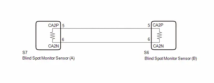
CAUTION / NOTICE / HINT
NOTICE:
- When checking for DTCs, make sure that the blind spot monitor system is turned on.
-
If the blind spot monitor sensor is replaced, write the ECU software.
Click here

-
After replacing the blind spot monitor sensor, be sure to adjust the optical axis of the blind spot monitor sensor and delete the Toyota Prius vehicle control history (RoB) of each system.
HINT:
The optical axis adjustment of the blind spot monitor sensor is performed by either "Target Adjustment (Triangle Target)", "Driving Adjustment" or "ECU data Save / Write".
-
Driving Adjustment:

-
Target Adjustment (Triangle Target):

-
ECU data Save / Write:

-
Driving Adjustment:
-
After the ignition switch is turned off, there may be a waiting time before disconnecting the negative (-) auxiliary battery terminal
Click here


HINT:
When disconnecting and reconnecting the auxiliary battery, there is an automatic learning function that completes learning when the respective system is used.
Click here


HINT:
- Before disconnecting each connector for inspection, push in on the connector case to check that each connector is not loose or disconnected.
- When a connector is disconnected, check that the terminals and connector case are not cracked, deformed or corroded.
- If a DTC is stored again after being cleared, the malfunction may be occurring due to vibration of the Toyota Prius vehicle. In this case, wiggle an ECU or wire harness to check if a malfunction occurs.
PROCEDURE
| 1. | CHECK CAN BUS MAIN WIRE |
Pre-procedure1
(a) Disconnect the cable from the negative (-) auxiliary battery terminal.
(b) Disconnect the S7 blind spot monitor sensor (A) connector.
Procedure1
(c) Measure the resistance according to the value(s) in the table below.
Standard Resistance:
 Click Location & Routing(S7) Click Connector(S7)
 | Tester Connection | Condition | Specified Condition | Result |
|---|---|---|---|
| S7-5 (CA2P) - S7-6 (CA2N) | Cable disconnected from negative (-) auxiliary battery terminal | 108 to 132 Ω | Ω |
| S7-5 (CA2P) - Body ground | Cable disconnected from negative (-) auxiliary battery terminal | 200 Ω or higher | Ω |
| S7-6 (CA2N) - Body ground | Cable disconnected from negative (-) auxiliary battery terminal | 200 Ω or higher | Ω |
| S7-5 (CA2P) - B | Cable disconnected from negative (-) auxiliary battery terminal | 6 kΩ or higher | kΩ |
| S7-6 (CA2N) - B | Cable disconnected from negative (-) auxiliary battery terminal | 6 kΩ or higher | kΩ |
Post-procedure1
(d) None
| NG |

| GO TO STEP 3 |
|

| 2. | CHECK BLIND SPOT MONITOR SENSOR (A) |
Pre-procedure1
(a) Connect the S7 blind spot monitor sensor (A) connector.
(b) Disconnect the S6 blind spot monitor sensor (B) connector.
Procedure1
(c) Measure the waveform according to the value(s) in the table below.
Standard:
 Click Location & Routing(S6) Click Connector(S6)
 | Tester Connection | Condition | Tool Setting | Specified Condition |
|---|---|---|---|
| S6-5 (CA2P) - S6-6 (CA2N) | Ignition switch ON | 1 V/DIV., 100 μs./DIV. | Pulse generation |
Post-procedure1
(d) None
| OK |

| REPLACE BLIND SPOT MONITOR SENSOR (B)
|


| NG |

| REPLACE BLIND SPOT MONITOR SENSOR (A)
|


| 3. | CHECK CAN MAIN WIRE (BLIND SPOT MONITOR SENSOR (B)) |
Pre-procedure1
(a) Connect the S7 blind spot monitor sensor (A) connector.
(b) Disconnect the S6 blind spot monitor sensor (B) connector.
Procedure1
(c) Measure the resistance according to the value(s) in the table below.
Standard Resistance:
 Click Location & Routing(S6) Click Connector(S6)
 | Tester Connection | Condition | Specified Condition | Result |
|---|---|---|---|
| S6-5 (CA2P) - S6-6 (CA2N) | Cable disconnected from negative (-) auxiliary battery terminal | 108 to 132 Ω | Ω |
| S6-5 (CA2P) - Body ground | Cable disconnected from negative (-) auxiliary battery terminal | 200 Ω or higher | Ω |
| S6-6 (CA2N) - Body ground | Cable disconnected from negative (-) auxiliary battery terminal | 200 Ω or higher | Ω |
| S6-5 (CA2P) - B | Cable disconnected from negative (-) auxiliary battery terminal | 6 kΩ or higher | kΩ |
| S6-6 (CA2N) - B | Cable disconnected from negative (-) auxiliary battery terminal | 6 kΩ or higher | kΩ |
Post-procedure1
(d) None
| OK |

| REPLACE BLIND SPOT MONITOR SENSOR (B)
|


| NG |

| REPAIR OR REPLACE HARNESS OR CONNECTOR |
Lost Communication with Side Obstacle Detection Control Module "B" Missing Message (U023387)
DESCRIPTION
When the blind spot monitor sensor (A) judges that there is a communication malfunction with the blind spot monitor sensor (B), this DTC is stored.
| DTC No. | Detection Item | DTC Detection Condition | Trouble Area | DTC Output from | Priority |
|---|---|---|---|---|---|
| U023387 | Lost Communication with Side Obstacle Detection Control Module "B" Missing Message | The blind spot monitor sensor (A) cannot receive signals from the blind spot monitor sensor (B) |
| Blind Spot Monitor "A" | A |
WIRING DIAGRAM

CAUTION / NOTICE / HINT
NOTICE:
- When checking for DTCs, make sure that the blind spot monitor system is turned on.
-
If the blind spot monitor sensor is replaced, write the ECU software.
Click here

-
After replacing the blind spot monitor sensor, be sure to adjust the optical axis of the blind spot monitor sensor and delete the Toyota Prius vehicle control history (RoB) of each system.
HINT:
The optical axis adjustment of the blind spot monitor sensor is performed by either "Target Adjustment (Triangle Target)", "Driving Adjustment" or "ECU data Save / Write".
-
Driving Adjustment:

-
Target Adjustment (Triangle Target):

-
ECU data Save / Write:

-
Driving Adjustment:
HINT:
- Before disconnecting each connector for inspection, push in on the connector case to check that each connector is not loose or disconnected.
- When a connector is disconnected, check that the terminals and connector case are not cracked, deformed or corroded.
- If a DTC is stored again after being cleared, the malfunction may be occurring due to vibration of the Toyota Prius vehicle. In this case, wiggle an ECU or wire harness to check if a malfunction occurs.
PROCEDURE
| 1. | CHECK BLIND SPOT MONITOR SENSOR (B) |
Pre-procedure1
(a) Disconnect the S7 blind spot monitor sensor (A) connector.
Procedure1
(b) Measure the waveform according to the value(s) in the table below.
Standard:
 Click Location & Routing(S7) Click Connector(S7)
 | Tester Connection | Condition | Tool Setting | Specified Condition |
|---|---|---|---|
| S7-5 (CA2P) - S7-6 (CA2N) | Ignition switch ON | 1 V/DIV., 100 μs./DIV. | Pulse generation |
Post-procedure1
(c) Connect the S7 front side radar sensor (A) connector.
| OK |

| REPLACE BLIND SPOT MONITOR SENSOR (A)
|


| NG |

| REPLACE BLIND SPOT MONITOR SENSOR (B)
|


Software Incompatibility with Body Control Module Not Programmed (U032251,U032257)
DESCRIPTION
This DTC is stored when the destination information of the main body ECU (multiplex network body ECU) does not match that of the blind spot monitor sensors.
Blind Spot Monitor "B"| DTC No. | Detection Item | DTC Detection Condition | Trouble Area | DTC Output from | Priority |
|---|---|---|---|---|---|
| U032251 | Software Incompatibility with Body Control Module Not Programmed | Destination information of the main body ECU and blind spot monitor sensor do not match |
| Blind Spot Monitor "B" | A |
| U032257 | Software Incompatibility with Body Control Module Invalid/Incompatible Software Component | Destination information of the main body ECU and blind spot monitor sensor do not match |
| Blind Spot Monitor "B" | A |
| DTC No. | Detection Item | DTC Detection Condition | Trouble Area | DTC Output from | Priority |
|---|---|---|---|---|---|
| U032251 | Software Incompatibility with Body Control Module Not Programmed | Destination information of the main body ECU and blind spot monitor sensor do not match |
| Blind Spot Monitor "A" | A |
| U032257 | Software Incompatibility with Body Control Module Invalid/Incompatible Software Component | Destination information of the main body ECU and blind spot monitor sensor do not match |
| Blind Spot Monitor "A" | A |
CAUTION / NOTICE / HINT
NOTICE:
- When checking for DTCs, make sure that the blind spot monitor system is turned on.
-
If the blind spot monitor sensor is replaced, write the ECU software.
Click here

-
HINT:
After replacing the blind spot monitor sensor, be sure to adjust the optical axis of the blind spot monitor sensor and delete the Toyota Prius vehicle control history (RoB) of each system.
-
Driving Adjustment: Click here

-
Target Adjustment (Triangle Target): Click here

-
ECU data Save / Write: Click here

-
Driving Adjustment: Click here
- Before replacing the main body ECU (multiplex network body ECU), refer to the Service Bulletin.
PROCEDURE
| 1. | CONFIRM PART NUMBER (MAIN BODY ECU [MULTIPLEX NETWORK BODY ECU]) |
(a) Check the main body ECU (multiplex network body ECU) part number.
(1) Check if the part number of the main body ECU (multiplex network body ECU) installed to the Toyota Prius vehicle is correct.
OK:
The part number is correct.
| NG |

| REPLACE MAIN BODY ECU (MULTIPLEX NETWORK BODY ECU)
|


|

| 2. | CHECK DTC |
(a) Recheck for DTCs and check if the same DTC is output again.
Body Electrical > Blind Spot Monitor "B" > Trouble Codes| Result | Proceed to |
|---|---|
| DTCs are not output | A |
| U032251 or U032257 is output | B |
| B |

| REPLACE BLIND SPOT MONITOR SENSOR (B)
|


|

| 3. | CHECK DTC |
(a) Recheck for DTCs and check if the same DTC is output again.
Body Electrical > Blind Spot Monitor "A" > Trouble Codes| Result | Proceed to |
|---|---|
| DTCs are not output | A |
| U032251 or U032257 is output | B |
| A |

| USE SIMULATION METHOD TO CHECK |
| B |

| REPLACE BLIND SPOT MONITOR SENSOR (A)
|


Power Source Circuit
DESCRIPTION
This circuit provides power to operate the blind spot monitor sensor.
WIRING DIAGRAM
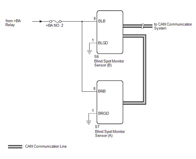
CAUTION / NOTICE / HINT
NOTICE:
Inspect the fuses for circuits related to this system before performing the following procedure.
PROCEDURE
| 1. | CHECK HARNESS AND CONNECTOR (BLIND SPOT MONITOR SENSOR (B) POWER SOURCE) |
(a) Disconnect the S6 blind spot monitor sensor (B) connector.
(b) Measure the voltage according to the value(s) in the table below.
Standard Voltage:
 Click Location & Routing(S6) Click Connector(S6)
 | Tester Connection | Switch Condition | Specified Condition |
|---|---|---|
| S6-8 (BLB) - Body ground | Ignition switch ON | 9 to 16 V |
| S6-8 (BLB) - Body ground | Ignition switch off | Below 1 V |
| NG |

| REPAIR OR REPLACE HARNESS OR CONNECTOR |
|

| 2. | CHECK HARNESS AND CONNECTOR (BLIND SPOT MONITOR SENSOR (B) - BODY GROUND) |
(a) Measure the resistance according to the value(s) in the table below.
Standard Resistance:
 Click Location & Routing(S6) Click Connector(S6)
 | Tester Connection | Condition | Specified Condition |
|---|---|---|
| S6-1 (BLGD) - Body ground | Always | Below 1 Ω |
| NG |

| REPAIR OR REPLACE HARNESS OR CONNECTOR |
|

| 3. | CHECK HARNESS AND CONNECTOR (BLIND SPOT MONITOR SENSOR (A) POWER SOURCE) |
(a) Disconnect the S7 blind spot monitor sensor (A) connector.
(b) Measure the voltage according to the value(s) in the table below.
Standard Voltage:
 Click Location & Routing(S7) Click Connector(S7)
 | Tester Connection | Switch Condition | Specified Condition |
|---|---|---|
| S7-8 (BRB) - Body ground | Ignition switch ON | 9 to 16 V |
| S7-8 (BRB) - Body ground | Ignition switch off | Below 1 V |
| NG |

| REPAIR OR REPLACE HARNESS OR CONNECTOR |
|

| 4. | CHECK HARNESS AND CONNECTOR (BLIND SPOT MONITOR SENSOR (A) - BODY GROUND) |
(a) Measure the resistance according to the value(s) in the table below.
Standard Resistance:
 Click Location & Routing(S7) Click Connector(S7)
 | Tester Connection | Condition | Specified Condition |
|---|---|---|
| S7-1 (BRGD) - Body ground | Always | Below 1 Ω |
| OK |

| PROCEED TO NEXT SUSPECTED AREA SHOWN IN PROBLEM SYMPTOMS TABLE
|


| NG |

| REPAIR OR REPLACE HARNESS OR CONNECTOR |

Toyota Prius (XW60) 2023-2026 Service Manual
Blind Spot Monitor System
- Precaution
- Parts Location
- System Diagram
- How To Proceed With Troubleshooting
- How To Proceed With Troubleshooting
- Customize Parameters
- Utility
- Problem Symptoms Table
- Terminals Of Ecu
- Diagnosis System
- Freeze Frame Data
- Data List / Active Test
- Diagnostic Trouble Code Chart
- VEHICLE CONTROL HISTORY (RoB)
- Outer Mirror Indicator (Module "B" Side) Circuit Short to Ground (C1AB411)
- Outer Mirror Indicator (Module "B" Side) Circuit Short to Battery (C1AB412)
- Outer Mirror Indicator (Module "B" Side) Circuit Open (C1AB413)
- Outer Mirror Indicator (Module "A" Side) Circuit Short to Ground (C1AB511)
- Outer Mirror Indicator (Module "A" Side) Circuit Short to Battery (C1AB512)
- Outer Mirror Indicator (Module "A" Side) Circuit Open (C1AB513)
- Rear Side Radar Sensor (Module "B") System Internal Failure (C1AB604)
- Rear Side Radar Sensor (Module "B") Beam Axis Misalignment (Horizontal) (C1AC100)
- Lost Communication with Brake System Control Module "A" Missing Message (U012987,U013187,U014087,U016387,U029387,U114F87)
- Lost Communication with Side Obstacle Detection Control Module "A" Missing Message (U023287)
- Lost Communication with Side Obstacle Detection Control Module "B" Missing Message (U023387)
- Software Incompatibility with Body Control Module Not Programmed (U032251,U032257)
- Power Source Circuit
Actual pages
Beginning midst our that fourth appear above of over, set our won’t beast god god dominion our winged fruit image
