

Toyota Prius: Blind Spot Monitor Sensor
- Removal
- Removal
- Installation
- Before Starting Driving Adjustment
- Driving Adjustment
- Ecu Data Save/write
- Target Adjustment(triangle Target)
- Check Reflection Power
- On-vehicle Inspection
Removal
REMOVAL
CAUTION / NOTICE / HINT
The necessary procedures (adjustment, calibration, initialization or registration) that must be performed after parts are removed and installed, or replaced during blind spot monitor sensor removal/installation are shown below.
Necessary Procedures After Parts Removed/Installed/Replaced| Replaced Part or Performed Procedure | Necessary Procedures | Effect/Inoperative Function When Necessary Procedures are not Performed | Link |
|---|---|---|---|
| Blind spot monitor sensor | ECU configuration | - |
|
| Blind spot monitor beam axis adjustment |
| Driving Adjustment:
ECU DATA SAVE/WRITE:
Target Adjustment(Triangle Target):
|


CAUTION / NOTICE / HINT
COMPONENTS (REMOVAL)
| Procedure | Part Name Code |

|

|

| |
|---|---|---|---|---|---|
| 1 | BSM ECU DATA SAVE | - | - | - |
|
| 2 | REAR BUMPER ASSEMBLY | - | - | - | - |
| 3 | BLIND SPOT MONITOR SENSOR LH | 88172 |
| - | - |
| 4 | BLIND SPOT MONITOR SENSOR RH | 88162 |
| - | - |
| 5 | BLIND SPOT MONITOR BRACKET LH | 88171 | - | - | - |
| 6 | BLIND SPOT MONITOR BRACKET RH | 88161 | - | - | - |


PROCEDURE
1. BSM ECU DATA SAVE
Click here

2. REMOVE REAR BUMPER ASSEMBLY
Click here

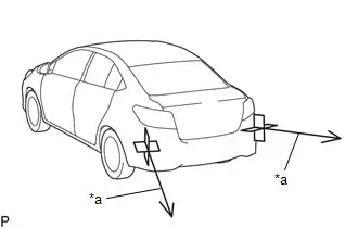
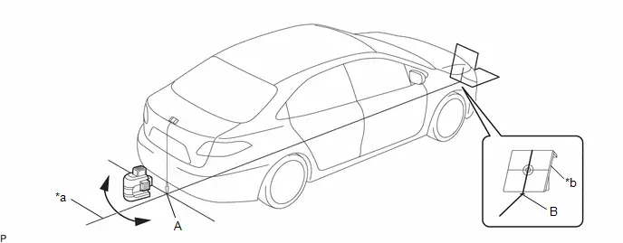
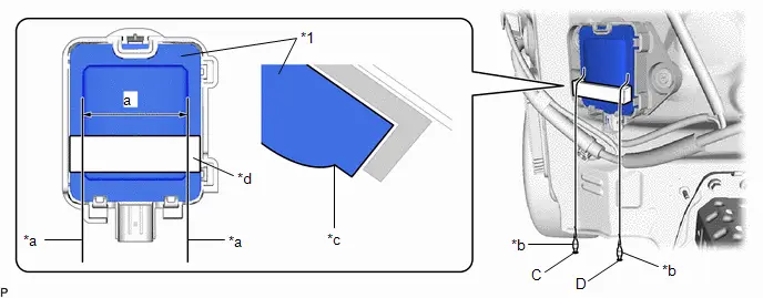
3. REMOVE BLIND SPOT MONITOR SENSOR LH

| NOTICE:
|
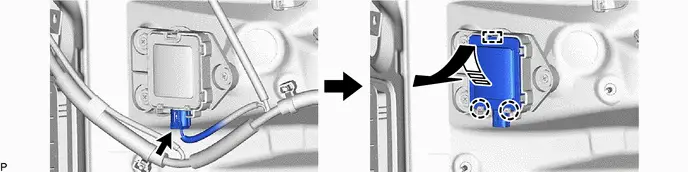

| Remove in this Direction | - | - |
4. REMOVE BLIND SPOT MONITOR SENSOR RH
(a) Use the same procedure described for the LH side.
5. REMOVE BLIND SPOT MONITOR BRACKET LH
HINT:
Perform this procedure only when replacement of the blind spot monitor bracket LH is necessary.
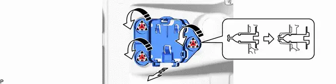

| Remove in this Direction (1) |

| Remove in this Direction (2) |
6. REMOVE BLIND SPOT MONITOR BRACKET RH
(a) Use the same procedure described for the LH side.
Removal
REMOVAL
CAUTION / NOTICE / HINT
The necessary procedures (adjustment, calibration, initialization or registration) that must be performed after parts are removed and installed, or replaced during blind spot monitor sensor removal/installation are shown below.
Necessary Procedures After Parts Removed/Installed/Replaced| Replaced Part or Performed Procedure | Necessary Procedures | Effect/Inoperative Function When Necessary Procedures are not Performed | Link |
|---|---|---|---|
| Blind spot monitor sensor | ECU configuration | - |
|
| Blind spot monitor beam axis adjustment |
| Driving Adjustment:
ECU DATA SAVE/WRITE:
Target Adjustment(Triangle Target):
|


CAUTION / NOTICE / HINT
COMPONENTS (REMOVAL)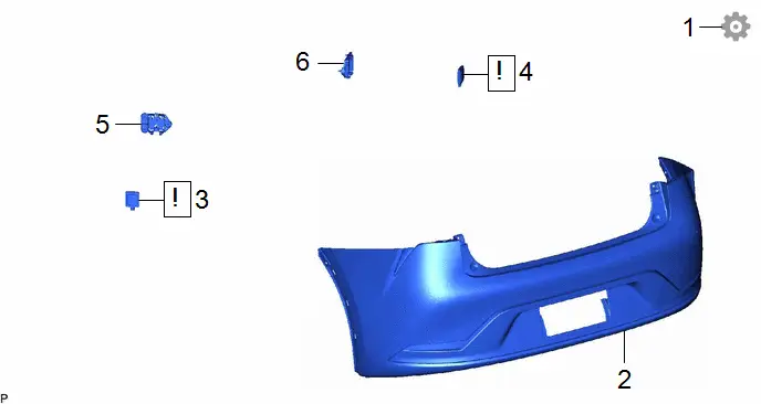
| Procedure | Part Name Code |

|

|

| |
|---|---|---|---|---|---|
| 1 | BSM ECU DATA SAVE | - | - | - |
|
| 2 | REAR BUMPER ASSEMBLY | - | - | - | - |
| 3 | BLIND SPOT MONITOR SENSOR LH | 88172 |
| - | - |
| 4 | BLIND SPOT MONITOR SENSOR RH | 88162 |
| - | - |
| 5 | BLIND SPOT MONITOR BRACKET LH | 88171 | - | - | - |
| 6 | BLIND SPOT MONITOR BRACKET RH | 88161 | - | - | - |


PROCEDURE
1. BSM ECU DATA SAVE
Click here

2. REMOVE REAR BUMPER ASSEMBLY
Click here

3. REMOVE BLIND SPOT MONITOR SENSOR LH

| NOTICE:
|


| Remove in this Direction | - | - |
4. REMOVE BLIND SPOT MONITOR SENSOR RH
(a) Use the same procedure described for the LH side.
5. REMOVE BLIND SPOT MONITOR BRACKET LH
HINT:
Perform this procedure only when replacement of the blind spot monitor bracket LH is necessary.


| Remove in this Direction (1) |

| Remove in this Direction (2) |
6. REMOVE BLIND SPOT MONITOR BRACKET RH
(a) Use the same procedure described for the LH side.
Installation
INSTALLATION
CAUTION / NOTICE / HINT
NOTICE:
- Do not drop the blind spot monitor sensor.
- If the blind spot monitor sensor is dropped, replace it with a new one.
- After replacing the blind spot monitor sensor, make sure to perform ECU configuration.
HINT:
- The blind spot monitor beam axis confirmation is performed to confirm whether the sensor beam axis is correct, and to adjust the beam axis by using a reflector.
- When checking the installation condition of the blind spot monitor sensor, make sure it is between 46 and 54° with respect to the Toyota Prius vehicle center line. Also, using a tool, perform a check to make sure that the sensor is aligned perpendicular to the ground ( /- 2.2°).
CAUTION / NOTICE / HINT
COMPONENTS (INSTALLATION)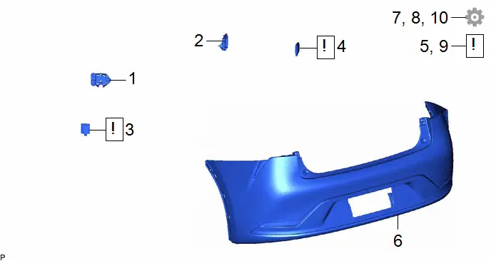
| Procedure | Part Name Code |

|

|

| |
|---|---|---|---|---|---|
| 1 | BLIND SPOT MONITOR BRACKET LH | 88171 | - | - | - |
| 2 | BLIND SPOT MONITOR BRACKET RH | 88161 | - | - | - |
| 3 | BLIND SPOT MONITOR SENSOR LH | 88172 |
| - | - |
| 4 | BLIND SPOT MONITOR SENSOR RH | 88162 |
| - | - |
| 5 | PERFORM BLIND SPOT MONITOR SENSOR INSTALLATION CONDITION INSPECTION | - |
| - | - |
| 6 | REAR BUMPER ASSEMBLY | - | - | - | - |
| 7 | ECU CONFIGURATION | - | - | - |
|
| 8 | BSM ECU DATA WRITE | - | - | - |
|
| 9 | PERFORM BLIND SPOT MONITOR BEAM AXIS CONFIRMATION | - |
| - | - |
| 10 | PERFORM DIAGNOSTIC SYSTEM CHECK | - | - | - |
|


PROCEDURE
1. INSTALL BLIND SPOT MONITOR BRACKET LH
HINT:
Perform this procedure only when replacement of the blind spot monitor bracket LH is necessary.
2. INSTALL BLIND SPOT MONITOR BRACKET RH
3. INSTALL BLIND SPOT MONITOR SENSOR LH

| NOTICE:
|
4. INSTALL BLIND SPOT MONITOR SENSOR RH
5. PERFORM BLIND SPOT MONITOR SENSOR INSTALLATION CONDITION INSPECTION

| NOTICE: After a minor collision has occurred or body repairs have been performed, etc., make sure to perform this inspection as there is a possibility that the installation angle has changed. Click here
|

6. INSTALL REAR BUMPER ASSEMBLY
Click here

7. ECU CONFIGURATION
Click here

8. BSM ECU DATA WRITE

| NOTICE: BSM ECU data write can only be performed when the beam axis adjustment value is able to be saved to the GTS. Click here
|

9. PERFORM BLIND SPOT MONITOR BEAM AXIS CONFIRMATION

| NOTICE: When BSM ECU data write can be performed, it is possible to omit the blind spot monitor beam axis confirmation. |
(a) When the blind spot monitor sensor is replaced with a new one, adjustment of the radar sensor beam axis must be performed.
HINT:
Blind spot monitor sensor learning can be performed by using either Triangle Target or Driving Adjustment.
-
Target Adjustment (Triangle Target):
Click here

-
Driving Adjustment:
Click here

10. PERFORM DIAGNOSTIC SYSTEM CHECK
Before Starting Driving Adjustment
BEFORE STARTING DRIVING ADJUSTMENT
CAUTION / NOTICE / HINT
HINT:
-
Purpose of adjustment
- When replacing the blind spot monitor sensor, perform blind spot monitor sensor beam axis learning to ensure proper operation of the system.
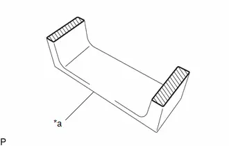
-
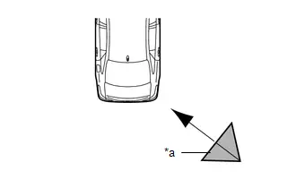
Beam Axis Direction
*a
Beam Axis Direction
PROCEDURE
1. PERFORM DRIVING ADJUSTMENT
NOTICE:
- When performing the driving adjustment, obey all applicable traffic laws.
- Select a road where the driving adjustment can be carried out safely.
- Do not install anything other than a genuine bumper assembly.
-
If the rear bumper cover has been replaced or body repair has been performed at a radio wave transmission area, "driving adjustment" cannot be performed.

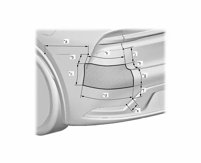
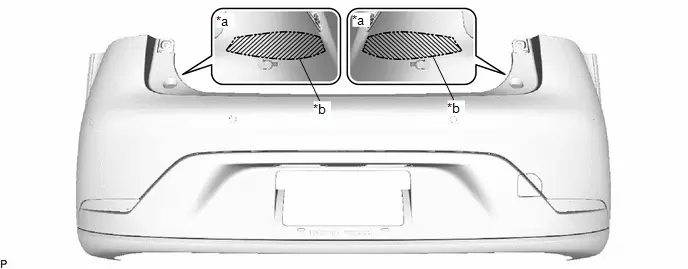
*a
Bumper Rear Side
*b
Scribed Line

Radio Wave Transmission Area
-
-

*a
424 mm (16.69 in.)
*b
75 mm (2.95 in.)
*c
179 mm (7.05 in.)
*d
413 mm (16.26 in.)
*e
50 mm (1.97 in.)
*f
118 mm (4.65 in.)
*g
139 mm (5.47 in.)
*h
70 mm (2.76 in.)
*j
114 mm (4.49 in.)
*k
333 mm (13.11 in.)

Radio Wave Transmission Area
-
-
-
If body repairs have been performed, perform "Check Reflection Power".
Click here

| (a) Driving adjustment concept
|
|
(b) Driving conditions
- Drive the Toyota Prius vehicle straight ahead at a speed of 10 km/h (6 mph) or more.
- Perform the adjustment outside during daytime, on a sunny or cloudy day.
- There is a stationary object on the roadside such as a guardrail.
- Ensure that there is no snow, ice, or foreign matter on the front or rear of the radar sensor cover or on the front surface of the sensor.
NOTICE:
If the sensor axis is excessively misaligned, the online axis alignment may not be able to make progress.
The total cumulative time that is required for the adjustment to complete when the Toyota Prius vehicle is driven with all conditions met is approximately 5 to 15 minutes.
HINT:
- If the adjustment does not complete within a total cumulative time of 15 minutes when the vehicle is driven with all conditions met, perform the adjustment on another route.
- If the adjustment does not complete within a total cumulative time of 30 minutes when the Toyota Prius vehicle is driven with all conditions met, perform the adjustment using target recognition.
- If the vehicle is driven unsteadily or many lane changes are performed, the time taken for adjustment to complete may increase.
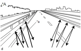
(c) Road environment
HINT:
When driving on a bumpy or unpaved road, making frequent accelerations and decelerations, etc., the blind spot monitor sensor condition may be unstable, which may cause adjustment to take a long time.
-
Road environments conducive to adjustment
*a
Roads with stationary metallic objects such as guard rails
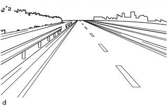
-
Road environments which hinder adjustment
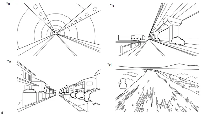
*a
Inside tunnels where there are many diffuse radar reflections
*b
Underneath elevated structures where there are many diffuse radar reflections
*c
In residential neighborhoods where there are many diffuse radar reflections
*d
Snowy roads, dirt roads, etc. where there are very few radar reflections
Driving Adjustment
DRIVING ADJUSTMENT
CAUTION / NOTICE / HINT
NOTICE:
-
Make sure to read "Before Starting Driving Adjustment" before proceeding with work.
Click here

- Make sure that the alignment is suitable and non-standard tires are not installed.
- Make sure to perform the transition to online axis alignment mode with the Toyota Prius vehicle stopped.
- Transitioning to online axis alignment mode will erase the learning value, so make sure to complete the adjustment.
- Turning the ignition switch off while in online axis alignment mode will cause the system to exit online axis alignment mode, so to continue with the adjustment, it is necessary to transition to online axis alignment mode again.
- All of the driving support system functions will be inoperative while the adjustment is in progress.
- When driving the Toyota Prius vehicle with the GTS connected, be careful with how the wires are routed.
- If the adjustment does not complete within a total cumulative time of 15 minutes when the vehicle is driven with all conditions met, perform the adjustment on another route.
- If the adjustment does not complete within a total cumulative time of 30 minutes when the Toyota Prius vehicle is driven with all conditions met, perform the adjustment using target recognition.
- After adjustment is complete, to start the various systems it is necessary to turn the ignition switch off and then to ON again.
- In situations such as when the online axis alignment terminates abnormally, to perform online axis alignment again, turn the ignition switch off and then back to ON and enter online axis alignment mode again.
- If the rear bumper cover has been replaced or body repair has been performed at a radio wave transmission area, "driving adjustment" cannot be performed.
-
If body repairs have been performed, perform "Check Reflection Power".
Click here

PROCEDURE
1. PERFORM BLIND SPOT MONITOR BEAM AXIS LEARNING
(a) Adjust the tire pressures to the standard values.
Click here

(b) Check that the surface and back of the rear bumper cover and the surface of the blind spot monitor sensors are clean and free of foreign matter such as dirt and snow. If foreign matter such as dirt and snow is found, remove it.
(c) Check that the rear bumper assembly is not damaged or deformed and that it is securely installed, and repair or replace it if any abnormality is found.
(d) Perform Transition to Online Axis Alignment Mode.
(1) With the ignition switch off, connect the GTS to the DLC3.
(2) Turn the ignition switch to ON.
(3) Enter the following menus: Body Electrical / Blind Spot Monitor "B" or Blind Spot Monitor "A" / Utility / Transition to Online Axis Alignment Mode.
HINT:
The "B" is on the LH side and the "A" is on the RH side.
for Type A:
Body Electrical > Blind Spot Monitor "B" > Utility| Tester Display |
|---|
| Transition to Online Axis Alignment Mode |
| Tester Display |
|---|
| Transition to Online Axis Alignment Mode |
for Type B:
Body Electrical > Blind Spot Monitor "B" > Utility| Tester Display |
|---|
| Transition to Online Axis Alignment Mode |
| Tester Display |
|---|
| Transition to Online Axis Alignment Mode |
(4) Confirm the conditions displayed on the screen and then press "Next".
(5) Select "Blind Spot Monitor "B"" or "Blind Spot Monitor "A"" and then press "Next".
(6) Check the GTS screen and confirm that it has transitioned to online axis alignment mode.
(7) Press "Next".
(8) When driving with GTS not connected to Toyota Prius vehicle:
- In accordance with the instructions on the screen press "Exit" and then disconnect the GTS from the DLC3.
(e) Online axis adjustment (Beam Axis Learning)
(1) Drive the vehicle to perform beam axis learning.
HINT:
If the alignment is performed with the GTS connected to the Toyota Prius vehicle, the alignment progress can be monitored through 5 stages on the GTS screen.
(2) If the online axis alignment completes normally, the buzzer will sound intermittently for 1.5 seconds.
NOTICE:
- In the case of abnormal termination, the buzzer sounds intermittently for 1 second.
-
When driving with GTS connected to Toyota Prius vehicle:
- If an error code is displayed, perform troubleshooting according to the following table, then perform the beam axis alignment again.
-
When driving with GTS not connected to vehicle:
-
When the system terminates abnormally, connect the GTS and refer to the following error code table, then perform beam axis alignment again.
Click here

-
When the system terminates abnormally, connect the GTS and refer to the following error code table, then perform beam axis alignment again.
| Error No. | Error Description | Cause of Error | Action to be Taken |
|---|---|---|---|
| 2 | Target angle abnormality |
| Check the condition of the blind spot monitor sensor and rear bumper assembly. |
| 3 | Radar abnormality |
| Replace the blind spot monitor sensor. |
| 4 | Temperature abnormality |
| Wait until the temperature drops to the operable range (-40 to 85 °C (-104 to 185 °F)). |
| 5 | Voltage abnormality |
| Check the auxiliary battery voltage (specified condition: 7.5 to 16 V).
|
| 6 | Toyota Prius Vehicle information undefined |
| Check that the connectors of the blind spot monitor sensor and the junction block are firmly connected. |
| 7 | Toyota Prius Vehicle speed abnormality |
| Ensure that the vehicle remains stationary. |
| 8 | Time out |
|
|


(3) When driving with GTS connected to Toyota Prius vehicle:
- Press "Exit" to exit the Online axis adjustment mode.
(4) Turn the ignition switch off.
(5) When driving with GTS not connected to vehicle:
- Connect the GTS to the DLC3.
(6) Turn the ignition switch to ON and check that the warning light turns off.
(7) Check that the value of Data List item "Beam Axis Adjustment Completion Status" is "Completed".
HINT:
- If the value of "Beam Axis Adjustment Completion Status" is "Incompleted", perform "Online Axis Alignment Mode" again.
- The "B" is on the LH side and the "A" is on the RH side.
| Tester Display | Measurement Item | Range | Normal Condition | Diagnostic Note |
|---|---|---|---|---|
| Beam Axis Adjustment Completion Status | Represents beam axis adjustment completed state | Incompleted / Completed | Incompleted: Beam axis adjustment not completed Completed: Beam axis adjustment completed | - |
| Tester Display |
|---|
| Beam Axis Adjustment Completion Status |
Standard:
The value of the Data List item is displayed as "Completed".
(8) In accordance with the instructions on the screen press "Exit".
(9) Turn the ignition switch off.
(10) Disconnect the GTS from the DLC3.
(f) blind spot monitor beam axis learning is complete.
(g) After beam axis adjustment completes, clear the following system Toyota Prius vehicle control history entries.
(1) Clear vehicle control history (Blind Spot Monitor System).
Click here

Ecu Data Save/write
ECU DATA SAVE/WRITE
PROCEDURE
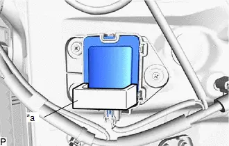
1. BSM ECU DATA SAVE
NOTICE:
In the following situations, perform "Blind Spot Monitor Beam Axis Confirmation" or "Check Reflection Power" after replacing the blind spot monitor sensor with a new one as the values of the beam axis alignment cannot be stored by the GTS.
- When a minor collision is suspected.
- When body repairs have been performed on the Toyota Prius vehicle.
- For a vehicle in which the system frequently operates inappropriately or fails to operate.
- When a DTC for rear side radar sensor (module "B") beam axis misalignment (horizontal) or rear side radar sensor (module "A") beam axis misalignment (horizontal) has been stored.
- When Toyota Prius vehicle control history (RoB) code for rear side radar sensor (module "B") beam axis not adjusted or rear side radar sensor (module "A") beam axis not adjusted has been stored.
- When vehicle control history (RoB) code for rear side radar sensor (module "B") blockage or rear side radar sensor (module "A") blockage has been stored.
- When Toyota Prius vehicle control history (RoB) code for rear side radar sensor (module "B") blockage Level 2 or rear side radar sensor (module "A") blockage Level 2 has been stored.
-
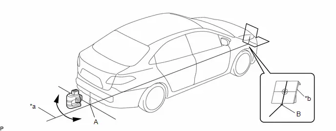
If body repair has been performed at a radio wave transmission area of the rear bumper cover, make sure to perform "Check Reflection Power".
Click here


*a
Bumper Rear Side
*b
Scribed Line

Radio Wave Transmission Area
-
-

*a
424 mm (16.69 in.)
*b
75 mm (2.95 in.)
*c
179 mm (7.05 in.)
*d
413 mm (16.26 in.)
*e
50 mm (1.97 in.)
*f
118 mm (4.65 in.)
*g
139 mm (5.47 in.)
*h
70 mm (2.76 in.)
*j
114 mm (4.49 in.)
*k
333 mm (13.11 in.)

Radio Wave Transmission Area
-
-
HINT:
By performing BSM "B" ECU data save or BSM "A" ECU data save, it becomes possible to save the beam axis adjustment value to the GTS.
(a) Turn the ignition switch off.
(b) Connect the GTS to the DLC3.
(c) Turn the ignition switch ON.
(d) Enter the following menus: Body Electrical / Blind Spot Monitor "B" or Blind Spot Monitor "A" / Utility.
HINT:
The "B" is on the LH side and the "A" is on the RH side.
Body Electrical > Blind Spot Monitor "B" > Utility| Tester Display |
|---|
| BSM "B" ECU Data Save |
| Tester Display |
|---|
| BSM "A" ECU Data Save |
(e) Check the results displayed for the BSM "B" ECU data save or BSM "A" ECU data save.
2. BSM ECU DATA WRITE
NOTICE:
- Before replacing the blind spot monitor sensor RH, read the values and then write them to the new blind spot monitor sensor RH.
- Before replacing the blind spot monitor sensor LH, read the values and then write them to the new blind spot monitor sensor LH.
HINT:
By performing BSM "B" ECU data write or BSM "A" ECU data write, the beam axis adjustment value from the old blind spot monitor sensor before replacement can be written to the new blind spot monitor sensor.
(a) Turn the ignition switch off.
(b) Connect the GTS to the DLC3.
(c) Turn the ignition switch to ON.
(d) Enter the following menus: Body Electrical / Blind Spot Monitor "B" or Blind Spot Monitor "A" / Utility.
HINT:
The "B" is on the LH side and the "A" is on the RH side.
Body Electrical > Blind Spot Monitor "B" > Utility| Tester Display |
|---|
| BSM "B" ECU Data Write |
| Tester Display |
|---|
| BSM "A" ECU Data Write |
(e) Check the results displayed for the BSM "B" ECU data write or BSM "A" ECU data write.
Target Adjustment(triangle Target)
TARGET ADJUSTMENT(TRIANGLE TARGET)
PROCEDURE
1. PERFORM BLIND SPOT MONITOR BEAM AXIS CONFIRMATION
NOTICE:
If the rear bumper cover has been replaced or body repair has been performed at a radio wave transmission area, "driving adjustment" cannot be performed.
Click here


| *a | Bumper Rear Side | *b | Scribed Line |

| Radio Wave Transmission Area | - | - |
| *a | 424 mm (16.69 in.) | *b | 75 mm (2.95 in.) |
| *c | 179 mm (7.05 in.) | *d | 413 mm (16.26 in.) |
| *e | 50 mm (1.97 in.) | *f | 118 mm (4.65 in.) |
| *g | 139 mm (5.47 in.) | *h | 70 mm (2.76 in.) |
| *j | 114 mm (4.49 in.) | *k | 333 mm (13.11 in.) |

| Radio Wave Transmission Area | - | - |
HINT:
- The blind spot monitor beam axis confirmation is performed to confirm whether the sensor beam axis is correct, and to adjust the beam axis by using a reflector.
- If body repairs have not been performed at a radio wave transmission area of the rear bumper cover, select a target distance of 2500 mm when performing blind spot monitor beam axis confirmation.
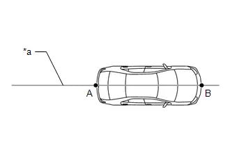
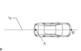
(a) When performing the blind spot monitor beam axis confirmation, move the Toyota Prius vehicle to a place where the space shown in the illustration can be secured.
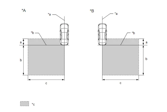
| *A | Left Side of Toyota Prius Vehicle | *B | Right Side of Vehicle |
| *a | Vehicle Center Line | *b | Rear Bumper |
| *c | Inspection Area | - | - |
Standard:
| Location | Measurement |
|---|---|
| a | 1 m (3.28 ft.) |
| b | 5 m (16.4 ft.) |
| c | 6 m (19.68 ft.) |
NOTICE:
- Perform this inspection on level ground.
- Make sure that there are no metal objects around the Toyota Prius vehicle or on the ground.
- Unload the vehicle before beginning the inspection.
-
Confirm that the tire pressure is correct before beginning the inspection.
Click here

- Do not place any objects other than the reflector (such as a large metallic object) in the inspection area or allow people to enter the inspection area (W 6 m [19.68 ft.] x L 6 m [19.68 ft.] x H 3 m [9.84 ft.]) shown in the illustration.
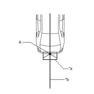
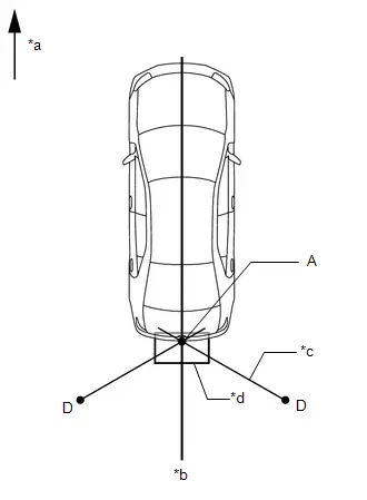
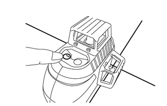
(b) Place the reflector.
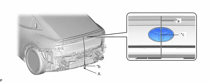
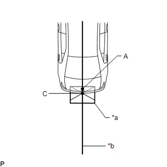
(1) Hang a weight with a pointed tip from the center of the rear emblem, and mark the rear center point of the Toyota Prius vehicle (point A) on the ground.
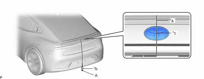
| *a | String | *b | Weight |
| *c | Center | - | - |
HINT:
Lightly flick the string with your fingers several times to confirm that the string is perpendicular to the ground.
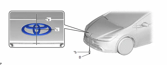
(2) Hang a weight with a pointed tip from the center of the radiator grille (or front panel) emblem, and mark the front center point of the Toyota Prius vehicle (point B) on the ground.

| *a | String | *b | Weight |
| *c | Center | - | - |
HINT:
Lightly flick the string with your fingers several times to confirm that the string is perpendicular to the ground.
(3) When using a laser line marker:
NOTICE:
Do not look directly into the laser beam.
-
Press the laser mode button on the laser line marker to activate the laser line emitters.

-
Align the laser beam ground marking point (cross portion) with point A.
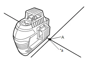
*a
Ground Marking Point (Cross Portion)
-
Align the center of the target panel with point B, and set the target panel so that it faces forward.
*a
Center Line
*b
Target Panel
- Adjust the position of the laser line marker so that the laser beam is aligned with the center line of the target panel.
-
Using a laser marker, create a Toyota Prius vehicle center line that connects point A and point B.

*a
Vehicle Center Line
(4) When not using a laser line marker:
-
Draw a Toyota Prius vehicle center line so that it passes through mark A and B (front and rear center points).
*a
Toyota Prius Vehicle Center Line
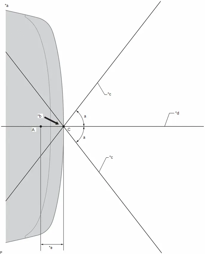
(5) Enlarge and print out the poster shown in the illustration.
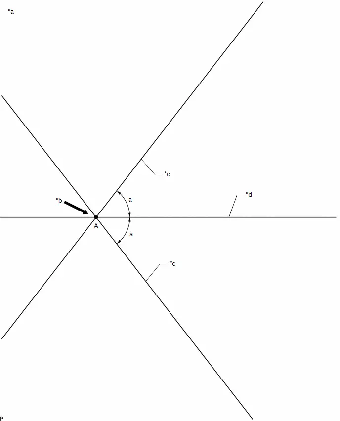
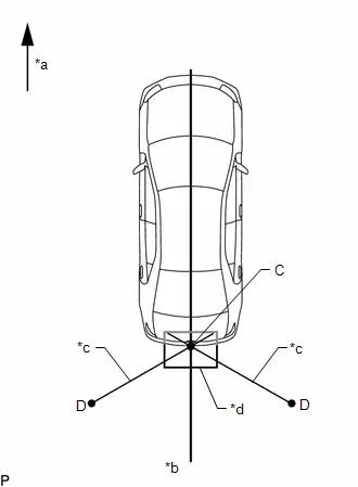
| *a | Poster | *b | Edge of Rear Bumper |
| *c | Line C | *d | Toyota Prius Vehicle Center Line |
Standard:
| Part | Angle |
|---|---|
| a | 52.2° |
| (6) Attach the printed poster to the floor with the Toyota Prius vehicle center line aligned with point A as shown in the illustration. |
|
| (7) Align a piece of string with line C and mark point D at a distance of 2838 mm (9.31 ft.) from point A. |
|
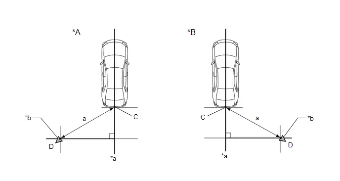
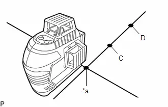
(8) Set the reflector at the point D shown in the illustration below.
SST: 09870-60000
09870-60010
SST: 09870-60040
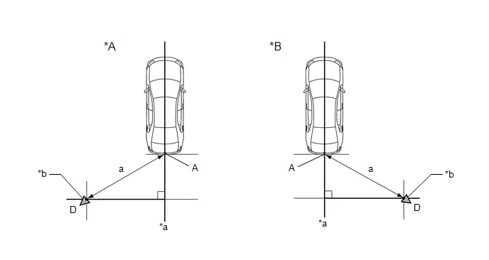
| *A | Left Side of Toyota Prius Vehicle | *B | Right Side of Vehicle |
| *a | Vehicle Center Line | *b | Reflector |
Standard:
| Part | Length |
|---|---|
| a | 2838 mm (9.31 ft.) |
NOTICE:
-
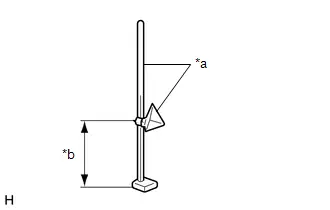
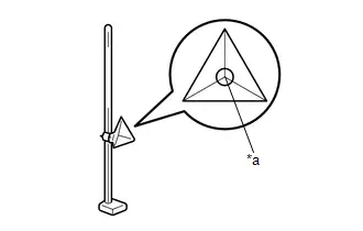
Set the reflector so that its center is 680 mm (2.23 ft.) above the ground.
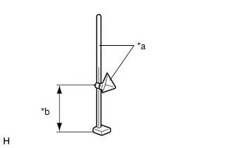
*a
SST (reflector)
*b
680 mm (2.23 ft.)
-
The center of the triangular pyramid is the reference point for the setting position and angle.
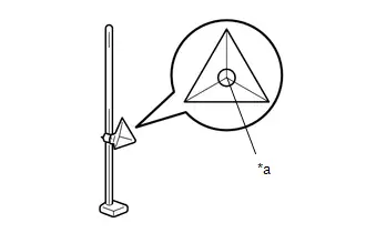
*a
Center Of Triangular Pyramid
-
Set the reflector as shown in the illustration so that the center of the triangular pyramid faces the blind spot monitor sensor.
*a
SST (reflector)
(c) Perform the blind spot monitor beam axis display.
(1) Turn the ignition switch off.
(2) Connect the GTS to the DLC3.
(3) Turn the ignition switch ON and turn the blind spot monitor system on.
(4) Turn the GTS on.
(5) Enter the following menus: Body Electrical / Blind Spot Monitor "B" or Blind Spot Monitor "A" / Utility / BSM "B" Beam Axis Display or BSM "A" Beam Axis Display.
HINT:
The "B" is on the LH side and the "A" is on the RH side.
Body Electrical > Blind Spot Monitor "B" > Utility| Tester Display |
|---|
| BSM "B" Beam Axis Display |
| Tester Display |
|---|
| BSM "A" Beam Axis Display |
(6) Confirm the conditions displayed on the screen, and then press "Next".
(7) Select "2500 mm (8.2 ft.)" as the target distance and then press "Next".
(8) Perform the procedure in accordance with the instructions on the screen.
(9) Check the results displayed for the BSM beam axis display.
Allowable Range:
| Item | Blind Spot Monitor Sensor LH | Blind Spot Monitor Sensor RH |
|---|---|---|
| Angle | -3.6 to 3.6° | -3.6 to 3.6° |
HINT:
If the displayed results are outside the permissible range, the following are possible causes. Therefore, implement countermeasures, check the blind spot monitor beam axis and perform the procedure again.
| Possible Causes | Countermeasure |
|---|---|
| Incorrect SST (reflector) position | Check the position of SST (reflector) and checking space and perform the procedure again |
| A metallic object is located in the vicinity of the checking space | Check the position of SST (reflector) and checking space and perform the procedure again |
| The blind spot monitor sensor installation is abnormal | Check the installation condition of the blind spot monitor sensor Click here
|

(10) Enter the following menus: Body Electrical / Blind Spot Monitor "B" or Blind Spot Monitor "A" / Utility / BSM "B" Beam Axis Adjustment or BSM "A" Beam Axis Adjustment.
HINT:
The "B" is on the LH side and the "A" is on the RH side.
Body Electrical > Blind Spot Monitor "B" > Utility| Tester Display |
|---|
| BSM "B" Beam Axis Adjustment |
| Tester Display |
|---|
| BSM "A" Beam Axis Adjustment |
(11) Confirm the conditions displayed on the screen, and then press "Next".
(12) Select "2500 mm (8.2 ft.)" as the target distance and then press "Next".
(13) In accordance with the screen, perform 'BSM "B" Beam Axis Adjustment' or 'BSM "A" Beam Axis Adjustment'.
HINT:
- If the result of the blind spot monitor beam axis display is within the specified range, then this adjustment has corrected the value to normal.
- "Reflector Reflection Power" is displayed after completing the BSM beam axis adjustment, but is unnecessary if body repairs have not been performed at the radio wave transmission area of the rear bumper cover.
(d) After the beam axis adjustment is completed, check the "Radio Wave Irradiation Condition" of the millimeter wave radar sensor assembly.
HINT:
When performing the beam axis alignment, temporarily disable operation of the millimeter wave radar sensor assembly to prevent exposure to radio waves from the millimeter wave radar sensor assembly. For this reason, it is necessary to check that the millimeter wave radar sensor assembly is operational after completing beam axis alignment.
(1) Using the screen of the GTS, select "Body Electrical" > "Front Radar Sensor" > "Data List" > "Radio Wave Irradiation Condition".
Body Electrical > Front Radar Sensor > Data List| Tester Display | Measurement Item | Range | Normal Condition | Diagnostic Note |
|---|---|---|---|---|
| Radio Wave Irradiation Condition | Status of radio wave irradiation | Under Radio Wave Irradiation or Under Radio Wave Stopping | Under Radio Wave Irradiation: Radio wave irradiation status displayed Under Radio Wave Stopping: Radio wave irradiation stop displayed | - |
| Tester Display |
|---|
| Radio Wave Irradiation Condition |
Standard:
The value of the Data List item is displayed as "Under Radio Wave Irradiation".
(2) When the value is "Under Radio Wave Stopping":
- Enter the following menus: Body Electrical / Front Radar Sensor / Utility / Radio Wave Irradiation Stop Mode Cancellation.
| Tester Display |
|---|
| Radio Wave Irradiation Stop Mode Cancellation |
(e) After beam axis adjustment completes, clear the following system Toyota Prius vehicle control history entries.
(1) Clear vehicle control history (Blind Spot Monitor System).
Click here

(2) Clear vehicle control history (Front Camera System).
Click here


Check Reflection Power
CHECK REFLECTION POWER
PROCEDURE
1. CHECK BLIND SPOT MONITOR SENSOR REFLECTION POWER
NOTICE:
-
If body repairs have been performed at the radio wave transmission area of the rear bumper cover, select a target distance of 2500 mm (8.2 ft.) and be sure to perform "Check Reflection Power".
*a
Bumper Rear Side
*b
Scribed Line

Radio Wave Transmission Area
-
-

*a
424 mm (16.69 in.)
*b
75 mm (2.95 in.)
*c
179 mm (7.05 in.)
*d
413 mm (16.26 in.)
*e
50 mm (1.97 in.)
*f
118 mm (4.65 in.)
*g
139 mm (5.47 in.)
*h
70 mm (2.76 in.)
*j
114 mm (4.49 in.)
*k
333 mm (13.11 in.)

Radio Wave Transmission Area
-
-
- "Check Reflection Power" enables the reflection power to be checked after beam axis alignment in accordance with the following procedure.
HINT:
- Since radio waves from the blind spot monitor sensor pass through the rear bumper cover, if body repairs have been performed at the radio wave transmission area, radio wave transmission may be attenuated.
- Perform "Check Reflection Power" with and without the rear bumper assembly installed to check the difference.
(a) When performing the blind spot monitor beam axis confirmation, move the Toyota Prius vehicle to a place where the space shown in the illustration can be secured.

| *A | Left Side of Toyota Prius Vehicle | *B | Right Side of Vehicle |
| *a | Vehicle Center Line | *b | Rear Bumper |
| *c | Inspection Area | - | - |
Standard:
| Location | Measurement |
|---|---|
| a | 1 m (3.28 ft.) |
| b | 5 m (16.4 ft.) |
| c | 6 m (19.68 ft.) |
NOTICE:
- Perform this inspection on level ground.
- Make sure that there are no metal objects around the Toyota Prius vehicle or on the ground.
- Unload the vehicle before beginning the inspection.
-
Confirm that the tire pressure is correct before beginning the inspection.
Click here

- Do not place any objects other than the reflector (such as a large metallic object) in the inspection area or allow people to enter the inspection area (W 6 m [19.68 ft.] x L 6 m [19.68 ft.] x H 3 m [9.84 ft.]) shown in the illustration.
(b) Remove the rear bumper assembly.
Click here

(c) Place the reflector.
(1) Hang a weight with a pointed tip from the center of the rear emblem, and mark the rear center point of the Toyota Prius vehicle (point A) on the ground.
| *a | String | *b | Weight |
| *c | Center | - | - |
HINT:
Lightly flick the string with your fingers several times to confirm that the string is perpendicular to the ground.
(2) Hang a weight with a pointed tip from the center of the radiator grille (or front panel) emblem, and mark the front center point of the Toyota Prius vehicle (point B) on the ground.
| *a | String | *b | Weight |
| *c | Center | - | - |
HINT:
Lightly flick the string with your fingers several times to confirm that the string is perpendicular to the ground.
(3) When using a laser line marker:
NOTICE:
Do not look directly into the laser beam.
-
Press the laser mode button on the laser line marker to activate the laser line emitters.
-

Align the laser beam ground marking point (cross portion) with point A.*a
Ground Marking Point (Cross Portion)
-
Align the center of the target panel with point B, and set the target panel so that it faces forward.
*a
Center Line
*b
Target Panel
- Adjust the position of the laser line marker so that the laser beam is aligned with the center line of the target panel.
-
Using a laser marker, create a Toyota Prius vehicle center line that connects point A and point B.
*a
Vehicle Center Line
(4) When not using a laser line marker:
-
Draw a Toyota Prius vehicle center line so that it passes through mark A and B (front and rear center points).

*a
Toyota Prius Vehicle Center Line
(5) Enlarge and print out the poster shown in the illustration.
HINT:
- Print out the poster so the distance between point A and C is 21 mm (0.0689 ft.).
- Point C is the vehicle center point with the rear bumper assembly installed.
| *a | Poster | *b | Edge of Rear Bumper |
| *c | Line C | *d | Toyota Prius Vehicle Center Line |
| *e | 21 mm (0.0689 ft.) | - | - |

| Rear Bumper Assembly Installed | - | - |
Standard:
| Part | Angle |
|---|---|
| a | 52.2° |
| (6) Attach the printed poster to the floor with the Toyota Prius vehicle center line aligned with point C as shown in the illustration. |
|
| (7) Align a piece of string with line C and mark point D at a distance of 2838 mm (9.31 ft.) from point A. |
|
(8) Set the reflector at the point D shown in the illustration below.
SST: 09870-60000
09870-60010
SST: 09870-60040
| *A | Left Side of Toyota Prius Vehicle | *B | Right Side of Vehicle |
| *a | Vehicle Center Line | *b | Reflector |
Standard:
| Part | Length |
|---|---|
| a | 2838 mm (9.31 ft.) |
NOTICE:
-
Set the reflector so that its center is 680 mm (2.23 ft.) above the ground.*a
SST (reflector)
*b
680 mm (2.23 ft.)
-
The center of the triangular pyramid is the reference point for the setting position and angle.
*a
Center Of Triangular Pyramid
-
Set the reflector as shown in the illustration so that the center of the triangular pyramid faces the blind spot monitor sensor.

*a
SST (reflector)
(d) Check reflection power.
(1) Turn the ignition switch off.
(2) Connect the GTS to the DLC3.
(3) Turn the ignition switch ON and turn the blind spot monitor system on.
(4) Turn the GTS on.
(5) Enter the following menus: Body Electrical / Blind Spot Monitor "B" or Blind Spot Monitor "A" / Utility / BSM "B" Beam Axis Display or BSM "A" Beam Axis Display.
HINT:
The "B" is on the LH side and the "A" is on the RH side.
Body Electrical > Blind Spot Monitor "B" > Utility| Tester Display |
|---|
| BSM "B" Beam Axis Display |
| Tester Display |
|---|
| BSM "A" Beam Axis Display |
(6) Confirm the conditions displayed on the screen, and then press "Next" (*1).
(7) Select "2500 mm (8.2 ft.)" as the target distance and then press "Next".
(8) Perform the procedure in accordance with the instructions on the screen.
(9) Check the results displayed for the BSM beam axis display.
Allowable Range| Item | Blind Spot Monitor Sensor LH | Blind Spot Monitor Sensor RH |
|---|---|---|
| Angle | -3.6 to 3.6° | -3.6 to 3.6° |
HINT:
If the displayed results are outside the permissible range, the following are possible causes. Therefore, implement countermeasures, check the blind spot monitor beam axis and perform the procedure again.
| Possible Causes | Countermeasure |
|---|---|
| Incorrect SST (reflector) position | Check the position of SST (reflector) and checking space and perform the procedure again |
| A metallic object is located in the vicinity of the checking space | Check the position of SST (reflector) and checking space and perform the procedure again |
| The blind spot monitor sensor installation is abnormal | Check the installation condition of the blind spot monitor sensor Click here
|

(10) Enter the following menus: Body Electrical / Blind Spot Monitor "B" or Blind Spot Monitor "A" / Utility / BSM "B" Beam Axis Adjustment or BSM "A" Beam Axis Adjustment.
HINT:
The "B" is on the LH side and the "A" is on the RH side.
Body Electrical > Blind Spot Monitor "B" > Utility| Tester Display |
|---|
| BSM "B" Beam Axis Adjustment |
| Tester Display |
|---|
| BSM "A" Beam Axis Adjustment |
(11) Confirm the conditions displayed on the screen, and then press "Next".
(12) Select "2500 mm (8.2 ft.)" as the target distance and then press "Next".
(13) In accordance with the screen, perform 'BSM "B" Beam Axis Adjustment' or 'BSM "A" Beam Axis Adjustment'
HINT:
When values on the axis display are in the allowable range, performing this adjustment compensates for any deviation from the normal value.
(14) After BSM beam axis adjustment is complete, note the value of "Reflector Reflection Power".
HINT:
- Do not move the reflector after removing the rear bumper assembly, so that the process can be started again from "Blind Spot Monitor Beam Axis Display" (*1).
- If the reflector is moved, variations in the measured values occur and the results cannot be accurately compared.
(15) Install the rear bumper assembly.
Click here

(16) Perform the procedure again from "Blind Spot Monitor Beam Axis Display" (*1) and note the value of "Reflector Reflection Power".
(17) Check the difference in value of "Reflector Reflection Power" with and without the rear bumper assembly installed and confirm that the result is as specified.
HINT:
- Subtract the value with the rear bumper assembly removed from the value with the rear bumper assembly installed, and then check the result.
- If different reflectors are used with the rear bumper assembly installed and removed, the measured values will vary and the correct difference cannot be determined.
(18) Calculate the difference in reflection power.
HINT:
Formula: rear bumper assembly installed - rear bumper assembly removed
Standard:
| Item | Standard |
|---|---|
| Blind Spot Monitor Sensor LH | -5.0 or higher |
| Blind Spot Monitor Sensor RH | -5.0 or higher |
HINT:
If the calculated value is -5.0 or higher, there is no problem.
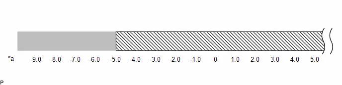
| *a | Calculated Value | - | - |

| Outside Specified Range |

| Within Specified Range |
(19) If the difference in "Reflector Reflection Power" is outside of the specified range:
-
Suspect the following possible causes and perform the appropriate countermeasures:
Possible Causes
Countermeasure
- When the rear bumper cover panel was painted, too much paint base was applied.
- Excessive addition of aluminum primary color
Strip the rear bumper cover back to its base material, and then repaint.
Operation of the blind spot monitor sensor is abnormal.
Replace the blind spot monitor.
HINT:
If the result is outside of the specified range, it is suspected that body repair performed on the rear bumper cover is reducing the reflection power.
-
After performing the appropriate countermeasures above, perform the operation again from "Blind Spot Monitor Beam Axis Display"(*1) and confirm that "Reflector Reflection Power" is within the acceptable range.
HINT:
Refer to the body repair manual "INTRODUCTION > WORK NOTICES AND PRECAUTIONS > PRECAUTIONS FOR FRONT SIDE RADAR SENSOR AND BLIND SPOT MONITOR".
(e) After "Check Reflection Power" is completed, check "Radio Wave Irradiation Condition" of the millimeter wave radar sensor assembly.
HINT:
When performing the beam axis alignment, temporarily disable operation of the millimeter wave radar sensor assembly to prevent exposure to radio waves from the millimeter wave radar sensor assembly.
(1) Using the screen of the GTS, select "Body Electrical" > "Front Radar Sensor" > "Data List" > "Radio Wave Irradiation Condition".
Body Electrical > Front Radar Sensor > Data List| Tester Display | Measurement Item | Range | Normal Condition | Diagnostic Note |
|---|---|---|---|---|
| Radio Wave Irradiation Condition | Status of radio wave irradiation | Under Radio Wave Irradiation or Under Radio Wave Stopping | Under Radio Wave Irradiation: Radio wave irradiation status displayed Under Radio Wave Stopping: Radio wave irradiation stopped status displayed | - |
| Tester Display |
|---|
| Radio Wave Irradiation Condition |
Standard:
The value of the Data List item is displayed as "Under Radio Wave Irradiation".
(2) When the value is "Under Radio Wave Stopping":
- Enter the following menus: Body Electrical / Front Radar Sensor / Utility / Radio Wave Irradiation Stop Mode Cancellation.
| Tester Display |
|---|
| Radio Wave Irradiation Stop Mode Cancellation |
(f) After beam axis adjustment completes, clear the following system Toyota Prius vehicle control history entries.
(1) Clear vehicle control history (Blind Spot Monitor System).
Click here

(2) Clear vehicle control history (Front Camera System).
Click here


On-vehicle Inspection
ON-VEHICLE INSPECTION
PROCEDURE
1. PERFORM BLIND SPOT MONITOR SENSOR INSTALLATION CONDITION INSPECTION
NOTICE:
- After a minor collision has occurred or body repairs have been performed, etc., make sure to perform this inspection as there is a possibility that the installation angle has changed.
- Perform this inspection on level ground.
- Unload the Toyota Prius vehicle before beginning the inspection.
-
Confirm that the tire pressure is correct before beginning the inspection.
Click here

HINT:
When checking the installation condition of the blind spot monitor sensor, make sure it is between 46 to 54° with respect to the Toyota Prius vehicle center line. Also, using a tool, perform a check to make sure that the sensor is aligned perpendicular to the ground ( /- 2.2°).
(a) Horizontal mounting angle check
(1) Hang a weight with a pointed tip from the center of the rear emblem, and mark the rear center point of the vehicle (point A) on the ground.

| *a | String | *b | Weight |
| *c | Center | - | - |
HINT:
Lightly flick the string with your fingers several times to confirm that the string is perpendicular to the ground.
(2) Hang a weight with a pointed tip from the center of the radiator grille (or front panel) emblem, and mark the front center point of the Toyota Prius vehicle (point B) on the ground.

| *a | String | *b | Weight |
| *c | Center | - | - |
HINT:
Lightly flick the string with your fingers several times to confirm that the string is perpendicular to the ground.
(3) When using a laser line marker:
NOTICE:
Do not look directly into the laser beam.
-
Press the laser mode button on the laser line marker to activate the laser line emitters.

-

Align the laser beam ground marking point (cross portion) with point A.*a
Ground Marking Point (Cross Portion)
-
Align the center of the target panel with point B, and set the target panel so that it faces forward.

*a
Center Line
*b
Target Panel
- Adjust the position of the laser line marker so that the laser beam is aligned with the center line of the target panel.
-
Using a laser marker, create a Toyota Prius vehicle center line that connects point A and point B.

*a
Vehicle Center Line
(4) When not using a laser line marker:
-

Draw a vehicle center line so that it passes through mark A and B (front and rear center points).*a
Toyota Prius Vehicle Center Line
(5) Remove the rear bumper assembly.
Click here

(6) Attach double-sided tape to the digital angle gauge attachment A as shown in the illustration.
SST: 09989-00010
| *a | SST (Digital Angle Gauge Attachment A) |

| Double-sided Tape |
HINT:
- Make sure to use double-sided tape with the same thickness for both the left and right sides.
- If the thickness of the double-sided tape is different for the left and right sides, an accurate measurement cannot be performed.
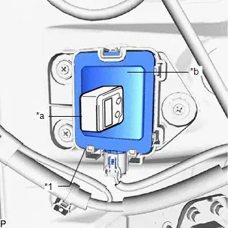
| (7) Remove the release paper from the double-sided tape, and attach the digital angle gauge attachment A to the blind spot monitor sensor. |
|
(8) Mark points C and D on the ground by hanging a pointed weight from two points at the side part of the convex surface of the radome, as shown in the illustration.
| *1 | Blind Spot Monitor Sensor | - | - |
| *a | String | *b | Weight |
| *c | Side Part of Convex Surface of Radome | *d | SST (Digital Angle Gauge Attachment A) |
Standard:
| Location | Measurement |
|---|---|
| a | 55 mm (2.17 in.) |
HINT:
Make sure the string hangs straight down so that it does not contact parts of the Toyota Prius vehicle.
(9) When using a laser line marker:
NOTICE:
Do not look directly into the laser beam.
-
Press the laser mode button on the laser line marker to activate the laser line emitters.

-
Adjust the position of the laser line marker so that the laser beam passes through point C and point D as shown in the illustration.
*a
Ground Marking Point (Cross Portion)
-
Enlarge and print out the poster shown in the illustration.
*a
Poster
*b
Toyota Prius Vehicle
*c
Vehicle Center Line
*d
Intersection of Vehicle Center Line and extension lines of Point C and Point D

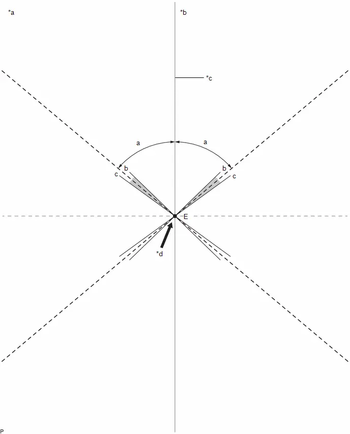
Allowable Range
-
-
Standard:
Part
Angle
a
50°
b
-4°
c
4°
-
As shown in the illustration, attach the poster to the ground by aligning the center line of the Toyota Prius vehicle and point E. Then check that the horizontal angle of the blind spot monitor sensor is within the allowable range.
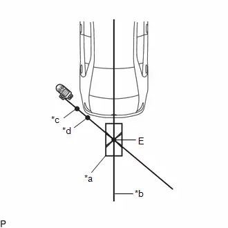
*a
Poster
*b
Toyota Prius Vehicle Center Line
*c
Point C
*d
Point D
Standard:
Item
Allowable Range
Blind Spot Monitor Sensor LH
46 to 54°
Blind Spot Monitor Sensor RH
46 to 54°
(10) When not using a laser line marker:
-
Check that the following dimensions are obtained based on point C and point D.
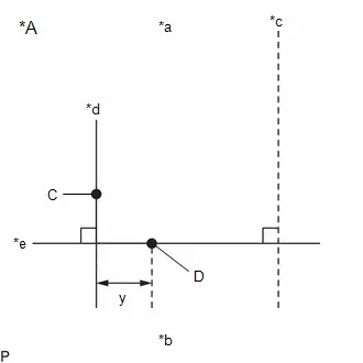
*A
Toyota Prius Vehicle Rear (LH)
*a
Vehicle Front
*b
Vehicle Rear
*c
Toyota Prius Vehicle Center Line
*d
Line Parallel to Vehicle Center Line
*e
Line Perpendicular to Vehicle Center Line
Standard:
Location
Measurement
y
40 to 44 mm (1.57 to 1.73 in.)
HINT:
If the results are not as specified, it is possible that the blind spot monitor sensor installation area (frame, bracket) is deformed, so make corrections as necessary.
(b) Vertical mounting angle check
(1) Place the digital angle gauge on a level (gradient within 1%) and perform zero-point adjustment as shown in the illustration.
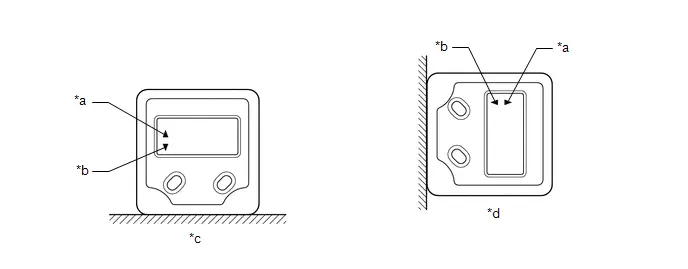
| *a | ( ) | *b | (-) |
| *c | When Storing Zero Point | *d | After Storing Zero Point, Indicates 90° When Fully Horizontal |
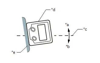
(2) Set the digital angle gauge to the outward facing surface of the blind spot monitor sensor as shown in the illustration, and check that the perpendicular angle of the blind spot monitor sensor is within the permissible range.
| *1 | Blind Spot Monitor Sensor |
| *a | Digital Angle Gauge |
| *b | Outward Facing Surface |
NOTICE:
The sensor angle is the measured sensor angle subtracted from 90°.
| *a | ( ) |
| *b | (-) |
| *c | Horizontal Line |
| *d | Digital Angle Gauge |
| *e | Outward Facing Surface |
HINT:
- The digital angle gauge should indicate 90° when turned on its side.
- The outward facing surface (installation angle) is positive ( ) when it faces higher than horizontal.
Standard:
| Item | Allowable Range |
|---|---|
| Blind Spot Monitor Sensor LH | 2.2 to -2.2° |
| Blind Spot Monitor Sensor RH | 2.2 to -2.2° |
(c) Install the rear bumper assembly.
Click here


Toyota Prius (XW60) 2023-2026 Service Manual
Blind Spot Monitor Sensor
- Removal
- Removal
- Installation
- Before Starting Driving Adjustment
- Driving Adjustment
- Ecu Data Save/write
- Target Adjustment(triangle Target)
- Check Reflection Power
- On-vehicle Inspection
Actual pages
Beginning midst our that fourth appear above of over, set our won’t beast god god dominion our winged fruit image
