

Toyota Prius: Advanced Park
- Precaution
- Parts Location
- System Diagram
- How To Proceed With Troubleshooting
- Customize Parameters
- Calibration
- Problem Symptoms Table
- Terminals Of Ecu
- Diagnosis System
- VEHICLE CONTROL HISTORY (RoB)
- Lost Communication with Gear Shift Control Module "A" Missing Message (U010387,U012687,U012987,U013187,U014087,U015587,U016387,U016487,U029387,U110687)
- Lost Communication with Image Processing Module "B" (ch2) (U117987)
- Vehicle does not Move to Set Parking Position
- Main Switch Circuit
Precaution
PRECAUTION
PRECAUTIONS WHEN REPLACING CLEARANCE WARING ECU ASSEMBLY
NOTICE:
When the clearance warning ECU assembly is replaced, update the ECU security key.
Click here 
PRECAUTION FOR DISCONNECTING CABLE FROM NEGATIVE AUXILIARY BATTERY TERMINAL
NOTICE:
After the ignition switch is turned off, there may be a waiting time before disconnecting the negative (-) auxiliary battery terminal.
Click here 
HINT:
When disconnecting and reconnecting the auxiliary battery, there is an automatic learning function that completes learning when the respective system is used.
Click here 

PRECAUTION FOR SERVICING Toyota Prius Vehicle
(a) After ECUs or parts are removed and installed, or replaced during inspection or servicing the vehicle, it is necessary to perform certain procedures (adjustment, calibration, initialization or registration).
Click here 
(b) Because the camera installation angle will change when the camera malfunctions or is replaced, it is necessary to perform registration of the memory function again.
(c) If tires other than those installed by the manufacturer are used when replacing tires, the system may not operate normally or the display positions of lines or frames shown on the radio and display receiver may be incorrect.
NOTES FOR EACH TELEVISION CAMERA ASSEMBLY
(a) Notes for each television camera assembly:
(1) The advanced park may not function properly if subjected to a severe blow by any hard object.
(2) Do not scrub the cover part of the camera (resin made). Scrubbing may scratch the cover and affect the image. Prevent organic solvents, waxes, bond removing solvents or glass coating from adhering to the cover. If such material adheres to the cover, clean it off immediately and wash it with water.
(3) Exposing the camera to a sudden temperature change may affect proper functioning of the camera.
(4) A clear image may not appear if the camera is dirty with snow, mud, etc. In that case, wash it with water and wipe off the lens. Use a detergent to remove dirt if necessary.
(5) When washing the Toyota Prius vehicle with a high-pressure washer, do not spray water on the television camera assembly or surrounding area. High-pressure water can damage the camera.
(b) Images may be unclear even in normal conditions if:
(1) The outer mirror switch assembly is operated (noise may occur in the image).
(2) Electrical devices are used in the cabin (noise may occur in the image).
(3) Accessories that generate radio waves have been installed (noise may occur in the image).
(4) The camera lens is frosted over (the image immediately after turning the ignition switch to ON may be blurred or darker than normal).
(5) The camera lens is dirty with snow, mud, etc.
(6) The lens of a camera is covered with foreign matter.
(7) A strong beam of light, such as a sunbeam or headlight, hits the camera.
(8) It is too dark around the camera (at night, etc.).
(9) The ambient temperature around the camera is either too high or too low.
(10) The Toyota Prius vehicle is tilted at a steep angle.
(11) The area around the vehicle is not sufficiently bright.
(12) The television camera assembly lens is scratched.
(13) The television camera assembly lens has drops of water on it or the humidity is high.
(14) When the camera is used under fluorescent lights, sodium lights or mercury lights, etc., the lights and the illuminated area may appear to flicker.
(15) As the side outer mirror is equipped with a parking assist light and the side camera reacts even to infrared rays, the camera image may differ from how objects look under visible light because the infrared rays in sunlight or halogen lights, or the light emitted from the parking assist light may cause the color of the camera image to become lighter or the color shade to change.
(c) In situations similar to the following, the parking space detection function may not operate correctly.
(1) The camera lens is dirty with snow, mud, etc.
(2) The lens of a camera is covered with foreign matter.
(3) A strong beam of light, such as a sunbeam or headlight, hits the camera.
(4) It is too dark around the camera (at night, etc.).
(5) The Toyota Prius vehicle is tilted at a steep angle.
(6) The television camera assembly lens is scratched.
(7) The television camera assembly lens has drops of water on it or the humidity is high.
PRECAUTION FOR PARKING ASSIST LIGHT
(a) Precautions
(1) Do not apply excessive force to the camera lens of the parking assist lights or subject them to a strong impact as it may affect proper functioning of the parking assist lights.
(2) Do not scrub the camera lens of the parking assist lights as scrubbing may scratch the lens and affect the quality of the image.
(3) The cover parts of the parking assist lights are made of resin. If any organic solvent, degreaser, wax or glass coating contacts a cover, immediately wipe it off and wash the cover with water or cracks may develop.
(4) Do not expose the parking assist lights to sudden temperature changes (such as pouring hot water in cold weather) as it may affect proper functioning of the panoramic view monitor system.
(5) If there is foreign matter such as water drops, snow or mud on the camera lenses of the parking assist lights, wash the cameras with a large amount of water and then wipe the lenses with a soft wet cloth. Do not scrub the camera lenses as scrubbing may scratch them and may adversely affect operation.
(6) When washing the Toyota Prius vehicle with a high-pressure washer, do not spray water on the parking assist lights or surrounding area. High-pressure water can damage the parking assist lights.
(b) If the quality of the image is poor even when the system is operating normally.
(1) A foreign object is attached to a camera lens
(2) A camera lens is covered with foreign matter, etc.
(3) The temperature around a camera lens is excessively high or low
(4) The Toyota Prius vehicle or road is on an incline
(5) A camera lens is scratched
(6) A camera lens has water droplets on it or the humidity is high
PRECAUTIONS FOR ULTRASONIC SENSOR
(a) Under the following conditions, the detection function may not function properly:
HINT:
- In very cold weather where a malfunction display appears, the sensor may not be able to detect obstacles.
- If a sensor malfunction is detected, advanced park DTCs will be stored.
- If the malfunction display appears, visually check the sensor first. If the sensor is free of foreign matter but the malfunction display remains, the sensor may have a malfunction.
(1) A sensor, the front bumper or rear bumper is not installed in the correct position.
(2) A sensor is improperly located due to damage to the front bumper or rear bumper.
(3) A sensor is covered with foreign matter, such as mud or snow (detection function returns to normal when the sensor is cleaned).
(4) A sensor is frozen (detection function returns to normal when the temperature of the sensor rises).
(5) A hand is blocking a sensor.
(6) The wind is strong.
(7) In severe weather such as fog, snow or a sandstorm.
(8) The height of the Toyota Prius vehicle has drastically changed due to loading (the nose tilts up or down).
(9) When washing the vehicle with a high-pressure washer, do not spray water directly on a sensor or surrounding area. high-pressure water can damage sensors.
(b) The detection range may be affected by the following conditions:
HINT:
Depending on the shape of a parked Toyota Prius vehicle or an obstacle such as a wall or post near a parking space, the detection range may change even though the sensors are operating normally.
(1) A sensor, the front bumper or rear bumper is not installed in the correct position.
(2) A sensor is improperly located due to damage to the front bumper or rear bumper.
(3) A sensor is covered with foreign matter, such as mud or snow.
(4) The Toyota Prius vehicle is in an excessively hot or excessively cold area.
(c) Under the following conditions, a detection error may occur:
HINT:
Depending on the shape of a parked vehicle or an obstacle such as a wall or post near a parking space, the detection range may change even though the sensors are operating normally.
(1) There is a wall near the parking space.
(2) A sensor, the front bumper or rear bumper is not installed in the correct position.
(3) A sensor is improperly located due to damage to the front bumper or rear bumper.
(4) Driving on a bumpy road, an unpaved road or in tall grass.
(5) Ultrasonic waves are received from the horn or parking sonar system of another Toyota Prius vehicle, a motorcycle engine, or the air brakes of a large vehicle.
(6) It is raining heavily or the sensor is splashed with water.
(7) The vehicle is tilted at a steep angle.
(8) The vehicle is equipped with a fender pole or a wireless antenna mechanism.
(9) A sensor is covered with foreign matter, such as mud or snow.
(d) Objects may not be detected by the sensors depending on its shape. The following are examples:
(1) Thin objects such as wires, fences and ropes.
(2) Materials such as snow that are likely to absorb ultrasonic waves.
(3) Objects with a sharp edge.
(4) Short objects.
(5) Objects that are tall and protrude toward the Toyota Prius vehicle above the detection range of the sensors.
(6) Objects other than parked vehicles, such as posts or walls.
(e) Other notices:
(1) The sensors cannot detect objects directly under the bumper. (A sensor may detect low objects and thin poles, and then lose track of them.)
(2) The sensors may not be able to detect obstacles that are too close to the sensor.
(3) The sensors may not be able to detect obstacles if the sensors have been dropped or subjected to a strong impact.
PRECAUTION FOR MEMORY FUNCTION
(a) If a parking position is registered under the following conditions, registration to the set position and the use of parking assist the next time the Toyota Prius vehicle is parked may not be possible.
(1) When a camera lens is dirty or covered with water droplets
(2) It is raining or snowing
(3) When the surrounding area is dark (at night, etc.)
(b) Registration of parking positions may not be possible in the following environments.
(1) Parking lots with insufficient road widths and insufficient space for parking positions.
(2) Parking lots without parking lines around the parking position that can be recognized by the system.
(c) If a parking position is registered in the following environments, parking assist may not start the next time the Toyota Prius vehicle is parked or the use of parking assist may not be possible at the set position.
(1) When shadows are cast on the parking space ( there is a carport over the parking space, etc.)
(2) When there are leaves, garbage, or other objects which will likely move, in the parking space
(3) When the road surface around the parking position is composed of the same pattern (brick, etc.).
(d) Parking in the set position using parking assist may not be possible under the following conditions.
(1) When the image is affected by the shadow of the Toyota Prius vehicle or trees, etc.
(2) When an obstacle is blocking the set parking position.
(3) When pedestrians or another moving vehicle is detected during parking assist.
(4) When the position at which the vehicle is stopped at the start of parking assist is different from that when registered.
(5) When the set parking position is cannot be reached due to wheels being blocked, etc.
(6) When the parking lines around the parking position have changed (due to road surface deterioration due to age or renovations, etc.).
(7) When sunlight conditions are different than those when registered (due to weather or time of day, etc.).
(8) When the sun is shining directly into a camera, such as in the early morning or evening.
(9) When the parking position is subjected to temporary light (such as that from the headlights of other Toyota Prius vehicles or security lights).
(10) There is foreign matter on the camera lens surface
(11) When there is a low protrusion on the road surface near the parking space.
(12) Parking spaces on a slope.
(13) When a camera has been splashed by hot or cold water and the lens has fogged up.
(14) When a camera lens is dirty or covered with water droplets.
(15) When accessories which obstruct the view of the camera are installed.
(e) It is necessary to perform registration again when control is stopped during memory function registration.
(f) When registering a parking space to the memory function, if the road surface cannot be detected "Location to be Registered Cannot be Found" may be displayed.
(g) If the intended parking area is not right next to the Toyota Prius vehicle when the memory function starts, the parking location may not be able to be detected correctly or the parking assist may not be able to continue functioning until the parking operation is complete.
(h) If a camera has been repaired or replaced, as the installation angle of the camera will have changed, it will be necessary to reregister parking spaces of the memory function.
Parts Location
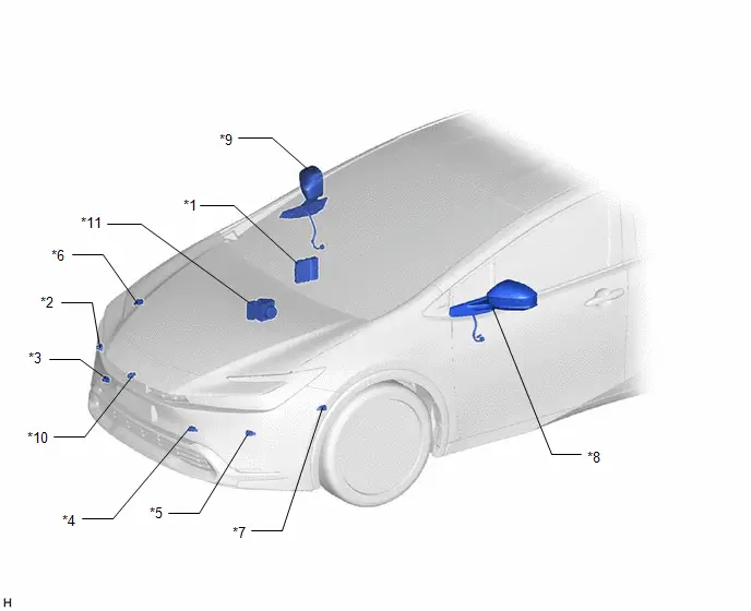
PARTS LOCATION
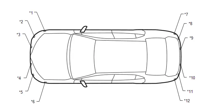
ILLUSTRATION
|
*1 |
HYBRID Toyota Prius Vehicle CONTROL ECU |
*2 |
FRONT CORNER ULTRASONIC SENSOR RH |
|
*3 |
FRONT CENTER ULTRASONIC SENSOR RH |
*4 |
FRONT CENTER ULTRASONIC SENSOR LH |
|
*5 |
FRONT CORNER ULTRASONIC SENSOR LH |
*6 |
FRONT SIDE ULTRASONIC SENSOR RH |
|
*7 |
FRONT SIDE ULTRASONIC SENSOR LH |
*8 |
OUTER REAR VIEW MIRROR ASSEMBLY LH - SIDE TELEVISION CAMERA ASSEMBLY LH - PARKING ASSIST LIGHT LH |
|
*9 |
OUTER REAR VIEW MIRROR ASSEMBLY RH - SIDE TELEVISION CAMERA ASSEMBLY RH - PARKING ASSIST LIGHT RH |
*10 |
FRONT TELEVISION CAMERA ASSEMBLY |
|
*11 |
BRAKE ACTUATOR ASSEMBLY - NO. 2 SKID CONTROL ECU |
- |
- |
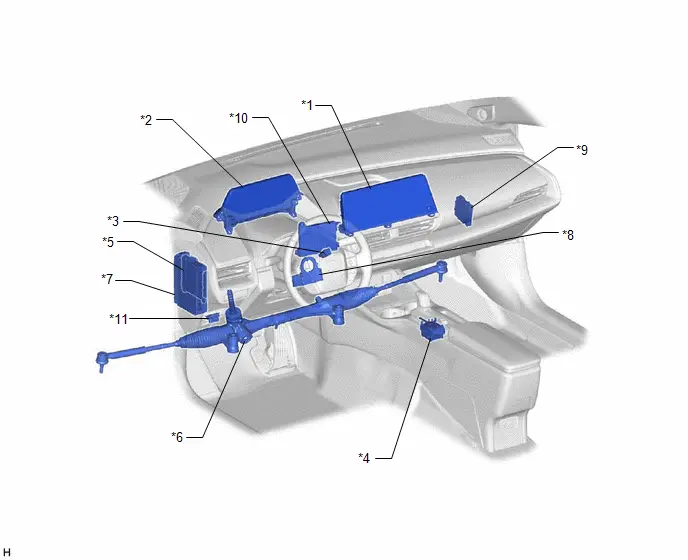
ILLUSTRATION
|
*1 |
RADIO AND DISPLAY RECEIVER ASSEMBLY |
*2 |
COMBINATION METER ASSEMBLY - MULTI-INFORMATION DISPLAY - CLEARANCE SONAR OFF INDICATOR |
|
*3 |
IPA MAIN SWITCH ASSEMBLY |
*4 |
TRANSMISSION FLOOR SHIFT ASSEMBLY - SHIFT CONTROL ECU |
|
*5 |
MAIN BODY ECU (MULTIPLEX NETWORK BODY ECU) |
*6 |
POWER STEERING ECU (RACK AND PINION POWER STEERING GEAR ASSEMBLY) |
|
*7 |
POWER DISTRIBUTION BOX ASSEMBLY - ECU-IGR NO.1 FUSE - ECU-IGR NO.3 FUSE |
*8 |
STEERING SENSOR |
|
*9 |
CLEARANCE WARNING ECU ASSEMBLY |
*10 |
AIR CONDITIONING AMPLIFIER ASSEMBLY |
|
*11 |
DLC3 |
- |
- |
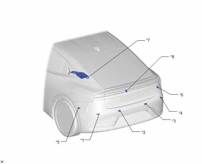
ILLUSTRATION
|
*1 |
REAR CORNER ULTRASONIC SENSOR LH |
*2 |
REAR CENTER ULTRASONIC SENSOR LH |
|
*3 |
REAR CENTER ULTRASONIC SENSOR RH |
*4 |
REAR CORNER ULTRASONIC SENSOR RH |
|
*5 |
REAR SIDE ULTRASONIC SENSOR LH |
*6 |
REAR SIDE ULTRASONIC SENSOR RH |
|
*7 |
PARKING ASSIST ECU |
*8 |
REAR TELEVISION CAMERA ASSEMBLY |
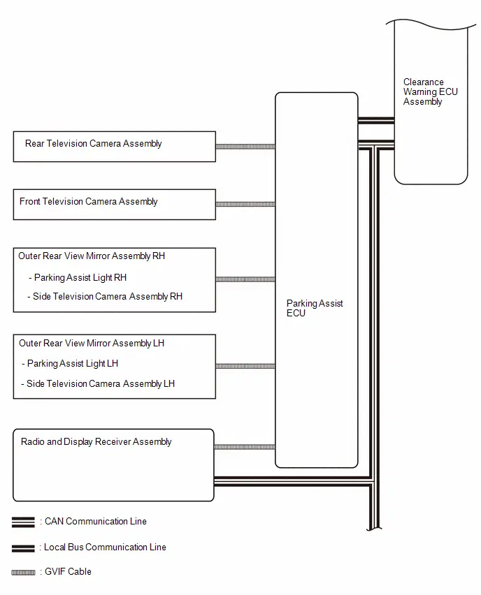
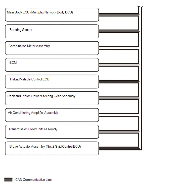
System Diagram
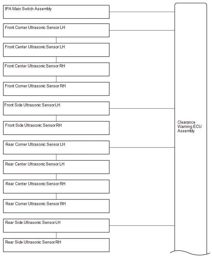
SYSTEM DIAGRAM
How To Proceed With Troubleshooting
CAUTION / NOTICE / HINT
HINT:
- Use the following procedure to troubleshoot the advanced park.
- *: Use the GTS.
PROCEDURE
|
1. |
Toyota Prius Vehicle BROUGHT TO WORKSHOP |
|

|
2. |
CUSTOMER PROBLEM ANALYSIS |
|

|
3. |
INSPECT AUXILIARY BATTERY VOLTAGE |
(a) Measure the auxiliary battery voltage with the ignition switch off.
Standard voltage:
11 to 14 V
If the voltage is below 11 V, replace or recharge the auxiliary battery before proceeding to the next step.
|

|
4. |
CHECK CAN COMMUNICATION SYSTEM* |
(a) Use the GTS to check if the CAN communication system is functioning normally.
Click here

|
Result |
Proceed to |
|---|---|
|
CAN communication system DTCs are not output |
A |
|
CAN communication system DTCs are output |
B |
| B |

|
GO TO CAN COMMUNICATION SYSTEM |
|

|
5. |
CHECK AUDIO AND VISUAL SYSTEM |
(a) Use the GTS to check if the audio and visual system is functioning normally.
Body Electrical > Navigation System > Trouble Codes Body Electrical > Navigation System > Clear DTCs|
Result |
Proceed to |
|---|---|
|
DTCs are not output |
A |
|
DTCs are output |
B |
| B |

|
GO TO AUDIO AND VISUAL SYSTEM |
|

|
6. |
CHECK PANORAMIC VIEW MONITOR SYSTEM* |
(a) Use the GTS to check if the panoramic view monitor system is functioning normally.
Chassis > Circumference Monitoring Camera Control Module > Trouble Codes Chassis > Circumference Monitoring Camera Control Module > Clear DTCs|
Result |
Proceed to |
|---|---|
|
DTCs are not output |
A |
|
DTCs are output |
B |
| B |

|
GO TO PANORAMIC VIEW MONITOR SYSTEM |
|

|
7. |
PROBLEM SYMPTOM CONFIRMATION |
|

|
8. |
CHECK FOR DTC* |
(a) Check for DTCs and note any codes that are output.
Body Electrical > Clearance Warning > Trouble Codes(b) Clear the DTCs.
Body Electrical > Clearance Warning > Clear DTCs(c) Try to reproduce the problem symptoms based on the recorded DTCs, and then check if the DTCs are output again.
Body Electrical > Clearance Warning > Trouble Codes|
Result |
Proceed to |
|---|---|
|
DTCs are output |
A |
|
DTCs are not output |
B |
| B |

|
GO TO STEP 10 |
|

|
9. |
DIAGNOSTIC TROUBLE CODE CHART |
(a) Refer to Diagnostic Trouble Code Chart.
Click here

NOTICE:
The clearance warning ECU assembly outputs DTCs for the following system. When DTCs other than those in Diagnostic Trouble Code Chart for the avanced park are output, refer to Diagnostic Trouble Code Chart for the relevant systems.
|
System |
Proceed to |
|---|---|
|
Intuitive Parking Assist-sensor System |
|
|
Parking Support Brake System |
|


| NEXT |

|
GO TO STEP 16 |
|
10. |
CHECK FOR Toyota Prius Vehicle CONTROL HISTORY(ROB) (PANORAMIC VIEW MONITOR SYSTEM)* |
HINT:
Refer to Vehicle Control History(ROB).
Click here

(a) Check for vehicle control history(ROB) and note any codes that are output.
Chassis > Circumference Monitoring Camera Control Module > Utility|
Tester Display |
|---|
|
Toyota Prius Vehicle Control History (RoB) |
|
Result |
Proceed to |
|---|---|
|
No vehicle control history(ROB) is output |
A |
|
Toyota Prius Vehicle control history(ROB) is output |
B |
| B |

|
GO TO VEHICLE CONTROL HISTORY(ROB) |
|

|
11. |
CHECK AUDIO AND VISUAL SYSTEM |
HINT:
Refer to Toyota Prius Vehicle Control History(ROB).
Click here

(a) Check for vehicle control history(ROB) and note any codes that are output.
Body Electrical > Navigation System > Utility|
Tester Display |
|---|
|
Toyota Prius Vehicle Control History (RoB) |
|
Result |
Proceed to |
|---|---|
|
No vehicle control history(ROB) is output |
A |
|
Toyota Prius Vehicle control history(ROB) is output |
B |
| B |

|
GO TO VEHICLE CONTROL HISTORY(ROB) |
|

|
12. |
CHECK FOR Toyota Prius Vehicle CONTROL HISTORY(ROB)* |
HINT:
Refer to Vehicle Control History(ROB).
Click here

(a) Check for vehicle control history(ROB) and note any codes that are output.
Body Electrical > Clearance Warning > Utility|
Tester Display |
|---|
|
Toyota Prius Vehicle Control History (RoB) |
|
Result |
Proceed to |
|---|---|
|
No vehicle control history(ROB) is output (Problem symptom does not occur) |
A |
|
No Toyota Prius vehicle control history(ROB) is output (Problem symptom occurs) |
B |
|
X20C0, X20C1, X20C2 or X20C3 is output |
C |
|
Any Toyota Prius vehicle control history(ROB) other than X20C0, X20C1, X20C2 or X20C3 is output |
D |
| B |

|
GO TO STEP 14 |
| C |

|
GO TO CALIBRATION |
| D |

|
GO TO Toyota Prius Vehicle CONTROL HISTORY(ROB) |
|

|
13. |
SYMPTOM SIMULATION |
(a) Refer to Symptom Simulation.
Click here

|

|
14. |
PROBLEM SYMPTOMS TABLE |
(a) Refer to Problem Symptoms Table.
Click here

|
Result |
Proceed to |
|---|---|
|
Fault is not listed in Problem Symptoms Table |
A |
|
Fault is listed in Problem Symptoms Table |
B |
| B |

|
GO TO STEP 16 |
|

|
15. |
OVERALL ANALYSIS AND TROUBLESHOOTING* |
(a) Terminals of ECU
Click here

(b) Data List / Active Test
Click here

|

|
16. |
CIRCUIT INSPECTION |
|

|
17. |
IDENTIFICATION OF PROBLEM |
|

|
18. |
REPAIR OR REPLACE |
|

|
19. |
CONFIRMATION TEST |
| NEXT |

|
END |
Customize Parameters
CUSTOMIZE PARAMETERS
CUSTOMIZE ADVANCED PARK
(a) Customize using radio and display receiver assembly
NOTICE:
- When the customer requests a change in a function, first make sure that the function can be customized.
- Be sure to make a note of the current settings before customizing.
- When troubleshooting a function, first make sure that the function is set to the default setting.
(1) Turn the ignition switch to ON.
(2) Turn the IPA main switch assembly on.
(3) On the radio and display receiver assembly, enter the following menus: Advanced Park.
|
Display |
Measurement Item |
Default |
Setting |
ECU |
|---|---|---|---|---|
| *: If set to Slightly Narrow or Narrow, the number of times the tires must be turned may increase | ||||
|
Speed Profile |
Sets the Toyota Prius vehicle speed during parking assist |
Standard |
Slow, Standard, Fast |
Clearance warning ECU assembly |
|
Obstacle Detection Range |
Sets the obstacle avoidance distance during parking assist |
Standard |
Standard, Far |
Clearance warning ECU assembly |
|
Preferred Parking Method |
Sets the parking method to be prioritized for display when both perpendicular parking and parallel parking are possible |
Parallel |
Back-in, Parallel |
Clearance warning ECU assembly |
|
Road Width Adjustment* |
Sets the road width to be used by the Toyota Prius vehicle during parking assist |
0 |
-3, -2, -1, 0, 1, 2, 3 |
Clearance warning ECU assembly |
|
Clear Registered parking lot |
Setting of Clear Registered parking lot display |
Standard |
Standard, Slightly Narrow, Narrow |
Clearance warning ECU assembly |
|
Preferred Parking Direction |
Setting of preferred parking direction display |
Back |
Back / progress |
Clearance warning ECU assembly |
|
Camera View When Parking |
Setting of the image displayed when parking |
Normal |
Wide / Normal |
Clearance warning ECU assembly |
|
Camera View When Exiting |
Setting of image displayed when parking |
Normal |
Wide / Normal |
Clearance warning ECU assembly |
|
Prior park in direction |
Setting of Prior park in direction |
forward |
forward / reverse |
Clearance warning ECU assembly |
|
Prior park out direction (Perpendicular) |
Setting of Prior park out direction (Perpendicular) |
left |
left / right |
Clearance warning ECU assembly |
|
Prior park out direction (Parallel) |
Setting of Prior park out direction (Parallel) |
left |
left / right |
Clearance warning ECU assembly |
|
Rear Accessory Setting |
Setting of length of component installed to rear of Toyota Prius vehicle |
0 |
10cm to 40cm |
Clearance warning ECU assembly |
|
Park Position Adjustment(fwd.) |
Setting of Park Position Adjustment(fwd.) |
0 |
20 to 60cm/-20cm to -60cm |
Clearance warning ECU assembly |
|
Park Position Adjustment (rev.) |
Setting of Park Position Adjustment (rev.) |
0 |
20 to 60cm/-20cm to -60cm |
Clearance warning ECU assembly |
Calibration
CALIBRATION
NOTICE:
When any of the following parts have been replaced, perform adjustment shown in the following table. If not, the advanced park may not operate correctly.
PRECAUTION (PROCEDURE 1)
(a) The necessary procedures (adjustment, calibration, initialization or registration) that must be performed after parts are removed and installed, or replaced during advanced park removal/installation are shown below.
|
Part Name |
Operation |
Adjustment Item |
Proceed to |
|---|---|---|---|
|
Parking assist ECU |
Replacement |
Adjust screen |
|
|
Suspension, tires, etc. |
The Toyota Prius vehicle height changes because of suspension or tire replacement |
Adjust screen |
|
|
No. 1 lower radiator grille |
When the radiator grille and ultrasonic sensor is damaged or deformed due to an accident or contact with other objects, etc., or the bumper installation area on the body is repaired. |
Measurement of ultrasonic sensor detection angle |
Procedure 2, 3 |
|
Ultrasonic sensor detection angle registration |
Procedure 4 |
||
|
Front television camera view adjustment |
|
|
|
Front bumper assembly |
When the front bumper and ultrasonic sensor is damaged or deformed due to an accident or contact with other objects, etc., or the bumper installation area on the body is repaired. |
Measurement of ultrasonic sensor detection angle |
Procedure 2, 3 |
|
Ultrasonic sensor detection angle registration |
Procedure 4 |
||
|
Front television camera view adjustment |
|
|
|
Rear bumper assembly |
When the rear bumper and ultrasonic sensor is damaged or deformed due to an accident or contact with other objects, etc., or the bumper installation area on the body is repaired. |
Measurement of ultrasonic sensor detection angle |
Procedure 2, 3 |
|
Ultrasonic sensor detection angle registration |
Procedure 4 |
||
|
Front television camera assembly |
|
Front television camera view adjustment |
|
|
Rear television camera assembly |
|
Rear television camera view adjustment |
|
|
|
Side television camera view adjustment |
|
|
Clearance warning ECU assembly |
Replacement |
Measurement of ultrasonic sensor detection angle |
Procedure 2, 3 |
|
Bumper type registration |
Procedure 4 |
||
|
Ultrasonic sensor detection angle registration |
|||
|
Update ECU security key |
|
||
|
Ultrasonic sensor |
Replacement |
Measurement of ultrasonic sensor detection angle |
Procedure 2, 3 |
|
Ultrasonic sensor detection angle registration |
Procedure 4 |


PREPARATION (PROCEDURE 2)
(a) Preparation
- Digital angle gauge
- Digital angle gauge attachment
- Masking tape (To prevent damage)
- A level
SST: 09989-00020
(b) Confirm levelness of floor surface.
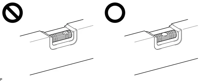
(1) Place a bubble level on a level surface and confirm that the bubble is centered.
NOTICE:
Make sure that there is no gravel, sand, etc., and that the surface is not undulating.
HINT:
By adjusting the direction of the bubble level, it is possible to find a position where the bubble is centered.
(2) Turn on the digital angle gauge.
(3) Place the digital angle gauge in the same location and direction as that of the bubble level where the levelness of the surface was confirmed.
NOTICE:
Confirm that the location and direction of the digital angle gauge is exactly the same as that of the bubble level.
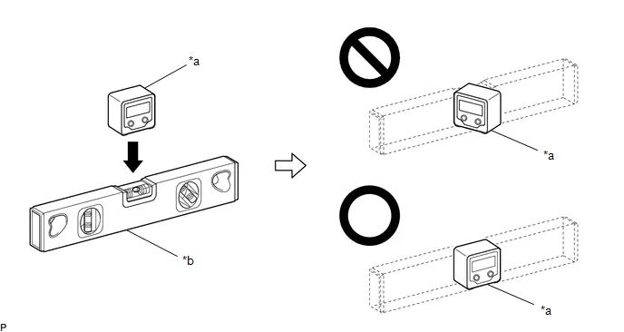
|
*a |
Digital Angle Gauge |
*b |
Level |
(4) Press the "ZERO" switch to memorize the zero point (perfectly level).
NOTICE:
Make sure that the digital angle gauge does not move when pressing the switch. If the digital angle gauge moves when the switch is pressed, an incorrect zero point may be memorized and it will not be possible to accurately check for levelness.
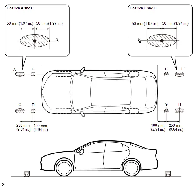
(5) Using the digital angle gauge in which the zero point (perfectly level) has been memorized, measure the angle of the floor surface at the 4 positions at the front of the Toyota Prius vehicle and the 4 positions at the rear of the vehicle as shown in the illustration.
NOTICE:
- Always position the digital angle gauge in the direction shown in the illustration.
- Make sure that there is no gravel, sand, etc., and that the floor surface is not undulating.
- When measuring the angle of the floor surface, avoid uneven areas such as joints between tiles.
HINT:
If necessary, the digital angle gauge can be placed anywhere within the specified area when measuring the angle of the floor surface for positions A, C, F and H.
 |
Confirmation Area |
- |
- |
(6) Using the following worksheet, calculate the average of the measurements taken at the 4 positions in front of the Toyota Prius vehicle, and calculate the average of the measurements taken at the 4 positions behind the vehicle. Confirm that the front measurement average and the rear measurement average are not more than approximately 0.37 degrees. Also, confirm that the front measurement average and the rear measurement average is less than 0.2 degrees.
NOTICE:
If the front measurement average and the rear measurement average are more than approximately 0.37 degrees or the difference between the front measurement average and the rear measurement average is 0.2 degrees or more, choose another work area as it is not possible to accurately check the installation angle of the sensors.
Worksheet: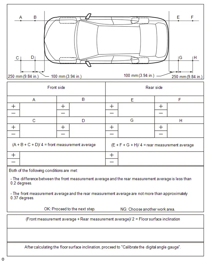
(7) Average the front measurement average and the rear measurement average, then round the answer to 1 decimal place (E.g. 0.0927 degrees is rounded to 0.1 degrees) to obtain the floor surface inclination value.
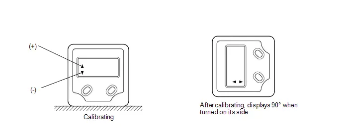
(8) Calibrate the digital angle gauge
Adjust the angle of the digital angle gauge until it reads the same value of the floor surface inclination, then press the "ZERO" switch to memorize the zero point (level with floor surface).
NOTICE:
Before pressing the "ZERO" switch, confirm that the digital angle gauge reading is positive if the floor angle inclination is positive, and negative if the floor angle inclination is negative.
(c) Prepare the digital angle gauge
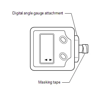
(1) Attach the digital angle gauge attachment to the digital angle gauge.
SST: 09989-00020
(2) Attach masking tape to the digital angle gauge attachment.
(d) Remove all luggage from the Toyota Prius vehicle.
(e) Adjust the tire inflation pressure to the specified pressure.
Click here
Click here 
SENSOR HEIGHT AND ALIGNMENT INSPECTION (PROCEDURE 3)
HINT:
Check if the installation angle of each ultrasonic sensor is appropriate.
(a) Preparation
(1) Visually check that the bumper, grille and ultrasonic sensors are installed properly and are not damaged.
NOTICE:
If the bumper, grille or any ultrasonic sensor is not installed correctly, the calibration may not be able to be completed.
(2) Check the tire pressures and adjust them if necessary.
Click here 
NOTICE:
- Ensure that the Toyota Prius vehicle is level in an area with no wind.
- Do not lean on the vehicle.
- Do not do anything that may affect the level of the vehicle during the calibration, such as getting in or out of the vehicle, or adding or removing luggage.
(b) Sensor height and alignment inspection
|
*1 |
Front Side Ultrasonic Sensor (FRS Sensor) |
*2 |
Front Corner Ultrasonic Sensor (FR Sensor) |
|
*3 |
Front Center Ultrasonic Sensor (FRC Sensor) |
*4 |
Front Center Ultrasonic Sensor (FLC Sensor) |
|
*5 |
Front Corner Ultrasonic Sensor (FL Sensor) |
*6 |
Front Side Ultrasonic Sensor (FLS Sensor) |
|
*7 |
Rear Side Ultrasonic Sensor (RRS Sensor) |
*8 |
Rear Corner Ultrasonic Sensor (RR Sensor) |
|
*9 |
Rear Center Ultrasonic Sensor (RRC Sensor) |
*10 |
Rear Center Ultrasonic Sensor (RLC Sensor) |
|
*11 |
Rear Corner Ultrasonic Sensor (RL Sensor) |
*12 |
Rear Side Ultrasonic Sensor (RLS Sensor) |
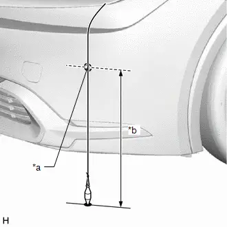
(c) Measure the installation height of the sensors.
|
*a |
Center of Sensor |
|
*b |
Sensor Height |
Standard Height (Front Bumper):
|
Sensor Location |
Sensor Height |
|---|---|
|
Front Center Ultrasonic Sensor |
434.9 to 488.1 mm (17.1 to 19.2 in.) |
|
Front Corner Ultrasonic Sensor |
473.8 to 527.1 mm (18.7 to 20.8 in.) |
|
Front Side Ultrasonic Sensor |
590.3 to 643.7 mm (23.2 to 25.3 in.) |
Standard Height (Front Bumper):
|
Sensor Location |
Sensor Height |
|---|---|
|
Front Center Ultrasonic Sensor |
511.0 to 637.8 mm (20.1 to 25.1 in.) |
|
Front Corner Ultrasonic Sensor |
511.0 to 655.2 mm (20.1 to 25.8 in.) |
|
Front Side Ultrasonic Sensor |
553.7 to 647.0 mm (21.8 to 25.5 in.) |
NOTICE:
If the installation height of a sensor is not as specified, it may not be possible to measure the sensor angles correctly. If so, unload the Toyota Prius vehicle and measure the installation height of the sensors again.
HINT:
Use the center of the sensor as the measuring point.
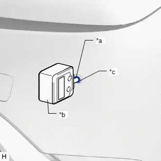
(d) Using the digital angle gauge, measure the angle of each sensor.
|
*a |
Digital Angle Gauge Attachment |
|
*b |
Digital Angle Gauge |
|
*c |
Ultrasonic Sensor |
(1) Measure the angle of the front sensors as shown in the illustration.
NOTICE:
Ensure that the digital angle gauge is flush with the face of the sensor.
(2) Measure the angle of the rear sensors.
NOTICE:
Ensure that the digital angle gauge is flush with the face of the sensor.
(3) Measure the angle of the side sensors.
NOTICE:
Ensure that the digital angle gauge is flush with the face of the sensor.
(4) Confirm that the angles of the sensors are as specified.
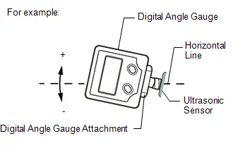
NOTICE:
The sensor angle is the measured sensor angle subtracted from 90°.
HINT:
- The digital angle gauge should indicate 90° when turned on its side.
- If the face of the sensor is tilted upwards, the sensor angle will be positive.
Standard Angle (Front Bumper):
|
Sensor Location |
Installation Angle |
|---|---|
|
Front Center Ultrasonic Sensor |
1.1 to 7.7° |
|
Front Corner Ultrasonic Sensor |
-2.7 to 4.0° |
|
Front Side Ultrasonic Sensor |
0.0 to 4.7° |
Standard Angle (Rear Bumper):
|
Sensor Location |
Installation Angle |
|---|---|
|
Rear Center Ultrasonic Sensor |
-0.6 to 6.0° |
|
Rear Corner Ultrasonic Sensor |
4.7 to 11.4° |
|
Rear Side Ultrasonic Sensor |
3.6 to 8.4° |
(5) If the angle or height of the sensors is not as specified, confirm that the installation is correct and then perform the inspection again.
HINT:
Check the following.
- Installation status of the front bumper assembly (rattling, uplifting)
- Installation status of the radiator grille assembly (rattling, uplifting)
- Installation status of the rear bumper assembly (rattling, uplifting)
- Fitting status of ultrasonic sensor and retainer
- Installation status of ultrasonic sensor cushion (uplifting, deformed)
- Installation status of the ultrasonic sensor retainer (rattling, uplifting)
REGISTRATION (PROCEDURE 4)
(a) Preparation
(1) Confirm that the following DTCs are not output.
|
System |
Proceed to |
|---|---|
|
Intuitive Parking Assist-sensor System |
|
|
Parking Support Brake System |
|
|
Advanced Park |
|


NOTICE:
If DTC C1AE087, C1AE187, C1AE287, C1AE387, C1AE487, C1AE587, C1AE687, C1AE787, C1AE887, C1AE987, C1AF187 or C1AF287 are output at this point, it is not a malfunction. Proceed with the calibration.
(b) Enter the following menus: Body Electrical / Clearance Warning / Utility.
Body Electrical > Clearance Warning > Utility|
Tester Display |
|---|
|
ECU Calibration |
(c) According to the display on the GTS, perform calibration.
(d) Enter the bumper type using the GTS.
|
Bumper Type |
Value |
|---|---|
|
Standard |
1 |
HINT:
If the clearance warning ECU assembly is replaced or removed and installed, it is necessary to perform bumper type registration.
(e) Using the GTS, enter the measured sensor values.
NOTICE:
The sensor angle is the measured sensor angle subtracted from 90°.
HINT:
The digital angle gauge should indicate 90° when turned on its side.
Problem Symptoms Table
PROBLEM SYMPTOMS TABLE
General|
Symptom |
Suspected Area |
Link |
|---|---|---|
|
The radio and display receiver assembly screen does not switch to the parking mode setting screen even when the IPA main switch assembly is pressed |
Proceed to "Main Switch Circuit" |
|
|
Proceed to "Clearance Warning ECU Power Source Circuit" |
|
|
|
Proceed to "Image from Camera for Panoramic View Monitor is Abnormal" |
|
|
|
Radio and display receiver assembly |
|
|
|
Clearance warning ECU assembly |
|


|
Symptom |
Suspected Area |
Link |
|---|---|---|
|
Advanced park abnormal image (color, distorted image) occurs regularly |
Proceed to "Image from Camera for Panoramic View Monitor is Abnormal" |
|
|
Advanced park abnormal image (color, distorted image) occurs temporarily |
Check operation conditions (Explain to the customer that temporary image distortion can be caused by a nearby source of electrical waves, such as being under a radio tower, next to a wireless truck, or near an airport) |
- |
|
Advanced park abnormal image (color, distorted image) occurs temporarily at night |
Proceed to "Image from Camera for Panoramic View Monitor is Abnormal" |
|


|
Symptom |
Suspected Area |
Link |
|---|---|---|
|
Advanced park system does not operate continuously |
Clearance warning ECU assembly |
|
|
Advanced park does not operate at night |
Proceed to "Image from Camera for Panoramic View Monitor is Abnormal" |
|
|
The estimated course lines do not match the Toyota Prius vehicle width extension lines when the steering wheel points straight ahead |
Check steering wheel installation angle |
|
|
Check rear television camera assembly installation condition |
|
|
|
Adjust screen |
|
|
|
Parking assist ECU |
|
|
|
The estimated course lines stop moving before the steering wheel is turned fully left or right |
Check that the panoramic view monitor system is operating normally |
- |
|
Displays "Advanced park malfunction visit your dealer" on the multi-information display |
Check Toyota Prius vehicle control history(ROB) |
|
|
Parking assist ECU |
|
|
|
Clearance warning ECU assembly |
|
|
|
"Advanced park cannot be used currently" is displayed on the radio and display receiver assembly |
Check Toyota Prius vehicle control history(ROB) |
|
|
Parking assist ECU |
|
|
|
Clearance warning ECU assembly |
|
|
|
"Remove the dirt" is displayed on the radio and display receiver assembly |
System determines that images cannot be detected due to dirt on the camera. If dirt is removed, normal control returns |
- |
|
Check Toyota Prius vehicle control history(ROB) |
|
|
|
Television camera assembly at the position displayed on the radio and display receiver assembly |
- |
|
|
Parking assist ECU |
|
|
|
Clearance warning ECU assembly |
|
|
|
Estimated course lines are not displayed. |
Check advanced park screen (check whether the parking guide lines have been hidden) |
- |
|
Steering sensor |
|
|
|
Parking assist ECU |
|
|
|
Assist operation frequently stops and the message "Not available in this environment" is displayed |
Check tires (tire size, tire pressure, tire wear) |
- |
|
Check surrounding conditions (no obstacles in front, short path where control is not possible, steps that cannot be driven over) |
- |
|
|
Check the setting of the "Road Width Adjustment" on the radio and display receiver assembly settings screen |
|
|
|
Clearance warning ECU assembly |
|
|
|
No guidance to the set target parking position |
Check the setting of the "Parking Path Adjustment" on the radio and display receiver assembly settings screen |
|
|
Proceed to "Toyota Prius Vehicle does not Move to Set Parking Position" |
|
|
|
When setting the target parking position, the initial display position of the target parking lines deviates greatly from the actual parking space (in parallel parking mode) |
Refer to the owner's manual, and after checking the operation conditions, perform the operation again |
- |
|
Proceed to "Precaution for Ultrasonic Sensor (Parking Space Detection Sensor)" |
|
|
|
Ultrasonic sensor on target parking position side |
- |
|
|
Front bumper assembly |
|
|
|
Rear bumper assembly |
|
|
|
Parking assist ECU |
|


|
Symptom |
Suspected Area |
Link |
|---|---|---|
|
IPA main switch assembly illumination does not turn on |
IPA main switch assembly |
|
|
Harness or connector |
- |
|
|
Touch switch operation is not accepted |
Audio and visual system - Check Touch Switch |
|
|
Radio and display receiver assembly |
|
|
|
Parking assist ECU |
|


|
Symptom |
Suspected Area |
Link |
|---|---|---|
|
Advanced park buzzer does not sound or volume is too low |
Parking assist ECU |
|
|
Clearance warning ECU assembly |
|
|
|
Radio and display receiver assembly |
|
|
|
Check that the meter / gauge system is operating normally |
- |


Terminals Of Ecu
TERMINALS OF ECU
CLEARANCE WARNING ECU ASSEMBLY

(a) Disconnect the R36 clearance warning ECU assembly connector.
(b) Measure the voltage and resistance on the wire harness side connector according to the value(s) in the table below.
|
Terminal No. (Symbol) |
Terminal Description |
Condition |
Specified Condition |
|---|---|---|---|
|
R36-1 (IG) - R36-31 (E) |
IG power source signal |
Ignition switch off |
Below 1 V |
|
Ignition switch ON |
11 to 14 V |
||
|
R36-11 (ISSW) - Body ground |
IPA main switch signal |
|
Below 1.5 V |
|
7.5 V or higher |
||
|
R36-31 (E) - Body ground |
Ground |
Always |
Below 1 Ω |
(c) Reconnect the R36 clearance warning ECU assembly connector.
(d) Measure the voltage and resistance and check for pulses according to the value(s) in the table below.
|
Terminal No. (Symbol) |
Terminal Description |
Condition |
Specified Condition |
|---|---|---|---|
|
R36-2 (BOF) - R36-31 (E) |
Power source for front sensor circuit |
Ignition switch off |
Below 1 V |
|
11 to 14 V |
||
|
R36-3 (E5) - R36-31 (E) |
Ground for front clearance sonar |
Always |
Below 1 Ω |
|
R36-4 (SOF) - R36-31 (E) |
Front sensor communication signal (Front clearance sonar sensor) |
|
Pulse generation (Refer to waveform 1) |
|
R36-5 (LIN1) - R36-6 (CSG1) |
Front side sensor communication signal (Front side clearance sonar sensor) |
|
Pulse generation (Refer to waveform 1) |
|
R36-6 (CSG1) - R36-31 (E) |
Ground for front side clearance sonar |
Always |
Below 1 Ω |
|
R36-7 (CSB1) - R36-6 (CSG1) |
Power source for front side sensor circuit |
|
11 to 14 V |
|
R36-19 (BOR) - R36-31 (E) |
Power source for rear sensor circuit |
Ignition switch off |
Below 1 V |
|
11 to 14 V |
||
|
R36-20 (E1) - R36-31 (E) |
Ground for rear clearance sonar |
Always |
Below 1 Ω |
|
R36-21 (SOR) - R36-31 (E) |
Rear sensor communication signal (Rear clearance sonar sensor) |
|
Pulse generation (Refer to waveform 2) |
|
R36-22 (LIN2) - R36-23 (CSG2) |
Rear side sensor communication signal (Rear side clearance sonar sensor) |
|
Pulse generation (Refer to waveform 2) |
|
R36-23 (CSG2) - R36-31 (E) |
Ground for rear side clearance sonar |
Always |
Below 1 Ω |
|
R36-24 (CSB2) - R36-23 (CSG2) |
Power source for rear side sensor circuit |
|
11 to 14 V |
(e) Using an oscilloscope, check waveform 1.
(1) Waveform 1 (Reference)
|
Item |
Content |
|---|---|
|
Measurement terminal |
|
|
Measurement setting |
5 V/DIV., 100 μs./DIV. |
|
Condition |
|
(f) Using an oscilloscope, check waveform 2.
(1) Waveform 2 (Reference)

|
Item |
Content |
|---|---|
|
Measurement terminal |
|
|
Measurement setting |
5 V/DIV., 100 μs./DIV. |
|
Condition |
|
PARKING ASSIST ECU
Click here 
Diagnosis System
DIAGNOSIS SYSTEM
ADVANCED PARK DIAGNOSIS SYSTEM
(a) For advanced park diagnosis, signals received by the parking assist ECU can be checked, and the advanced can be calibrated, adjusted and checked using the radio and display receiver assembly.
NOTICE:
Depending on the parts that are replaced or operations that are performed during Toyota Prius vehicle inspection or maintenance, calibration of other systems as well as the advanced park may be needed.
Click here 
HINT:
The displayed screens and items may differ depending on vehicle specifications.
DIAGNOSIS SCREEN TRANSITION (VIEW ADJUSTMENT)
Click here 
DIAGNOSIS SCREEN TRANSITION (CAMERA CHECK)
Click here 
DIAGNOSIS SCREEN TRANSITION (DIAG CHECK)
Click here 
DIAGNOSTIC MODE
(a) Diagnostic mode
Click here 
(b) System check (check using system check mode screen)
Click here 
(c) Finish diagnostic mode.
Click here 
SIGNAL CHECK (PARKING ASSIST ECU INPUT SIGNAL)
Click here 
DIAG CHECK
Click here 
CAMERA CHECK
Click here 
CALIBRATION WHEN SERVICING Toyota Prius Vehicle
NOTICE:
Depending on the parts that are replaced or operations that are performed during vehicle inspection or maintenance, calibration of other systems as well as the panoramic view monitor system may be needed.
Click here 
VEHICLE CONTROL HISTORY (RoB)
VEHICLE CONTROL HISTORY (RoB)
VEHICLE CONTROL HISTORY(ROB) (CLEARANCE WARNING)
HINT:
Part of the control history can be confirmed using the vehicle control history(ROB).
Click here

VEHICLE CONTROL HISTORY(ROB) (PANORAMIC VIEW MONITOR SYSTEM)
HINT:
Part of the control history can be confirmed using the Toyota Prius vehicle control history(ROB).
Click here


VEHICLE CONTROL HISTORY (AIRBAG)
HINT:
Part of the control history can be confirmed using the vehicle control history.
Click here

Lost Communication with Gear Shift Control Module "A" Missing Message (U010387,U012687,U012987,U013187,U014087,U015587,U016387,U016487,U029387,U110687)
DESCRIPTION
These DTCs are stored if there is a malfunction in the CAN communication system connected to the clearance warning ECU assembly.
HINT:
If CAN communication system DTCs are stored, they may also be stored in other systems.
|
DTC No. |
Detection Item |
DTC Detection Condition |
Trouble Area |
DTC Output from |
Priority |
|---|---|---|---|---|---|
|
U010387 |
Lost Communication with Gear Shift Control Module "A" Missing Message |
Lost communication with shift control ECU |
CAN communication system |
Clearance Warning |
B |
|
U012687 |
Lost Communication with Steering Angle Sensor Module Missing Message |
Lost communication with steering sensor |
CAN communication system |
Clearance Warning |
B |
|
U012987 |
Lost Communication with Brake System Control Module Missing Message |
Lost communication with No. 2 skid control ECU (brake actuator assembly) |
CAN communication system |
Clearance Warning |
B |
|
U013187 |
Lost Communication with Power Steering Control Module Missing Message |
Lost communication with EPS ECU |
CAN communication system |
Clearance Warning |
B |
|
U014087 |
Lost Communication with Body Control Module Missing Message |
Lost communication with main body ECU |
CAN communication system |
Clearance Warning |
B |
|
U015587 |
Lost Communication with Instrument Panel Cluster (IPC) Control Module Missing Message |
Lost communication with combination meter assembly |
CAN communication system |
Clearance Warning |
B |
|
U016387 |
Lost Communication with Navigation Control Module |
Lost communication with radio and display receiver assembly |
CAN communication system |
Clearance Warning |
B |
|
U016487 |
Lost Communication with HVAC Control Module Missing Message |
Lost communication with air conditioning amplifier assembly |
CAN communication system |
Clearance Warning |
B |
|
U029387 |
Lost Communication with Hybrid/EV Powertrain Control Module Missing Message |
Lost communication with hybrid Toyota Prius vehicle control ECU |
CAN communication system |
Clearance Warning |
B |
|
U110687 |
Lost Communication with Electric Parking Brake Module Missing Message |
Lost communication with No. 2 skid control ECU (brake actuator assembly) |
CAN communication system |
Clearance Warning |
B |
PROCEDURE
|
1. |
CLEAR DTC |
(a) Clear the DTCs.
Body Electrical > Clearance Warning > Clear DTCs
|

|
2. |
CHECK FOR DTC |
(a) Check for DTCs.
Body Electrical > Clearance Warning > Trouble CodesHINT:
- If CAN communication system DTCs are stored, they may also be stored in other systems.
- If the CAN communication system has been inspected and repaired in other systems, the DTCs will not be output when rechecking for DTCs.
- If these DTCs are output frequently, duplicate the conditions that caused the problem symptoms and perform the inspection again, even though DTCs were not output when rechecking for DTCs.
|
Result |
Proceed to |
|---|---|
|
DTCs are not output |
A |
|
U010387, U012687, U012987, U013187, U014087, U015587, U016387, U016487, U029387 or U110687 is output |
B |
| A |

|
USE SIMULATION METHOD TO CHECK |
| B |

|
GO TO CAN COMMUNICATION SYSTEM |
Lost Communication with Image Processing Module "B" (ch2) (U117987)
DESCRIPTION
This DTC is output when the clearance warning ECU assembly detects lost communication with the parking assist ECU.
|
DTC No. |
Detection Item |
DTC Detection Condition |
Trouble Area |
DTC Output from |
Priority |
|---|---|---|---|---|---|
|
U117987 |
Lost Communication with Image Processing Module "B" (ch2) |
The clearance warning ECU assembly is unable to receive communication from the parking assist ECU |
|
Clearance Warning |
A |
|
Pattern |
DTC output part name (Display on GTS) |
Suspected Area (Malfunction Status) |
|||
|---|---|---|---|---|---|
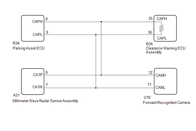
|
Clearance warning ECU assembly |
Parking assist ECU |
Forward Recognition Camera |
Millimeter wave Radar sensor assembly |
||
|
Clearance Warning |
Circumference Monitoring Camera Control Module |
Front Recognition Camera |
|||
|
U117987 |
U11B687 |
U023587 |
U010487 |
||
| ○: DTC is output
-: DTC is not output |
|||||
|
Pattern 1 |
○ |
○ |
○ |
○ |
Harness or connector (Open or short) |
|
Millimeter wave radar sensor assembly (Internal malfunction) |
|||||
|
Clearance warning ECU assembly (Internal malfunction) |
|||||
|
Parking assist ECU (Internal malfunction) |
|||||
|
Forward recognition camera (Internal malfunction) |
|||||
|
Pattern 2 |
○ |
○ |
- |
- |
Harness or connector (Open or short) |
|
Parking assist ECU (Internal malfunction) |
|||||
|
Clearance warning ECU assembly (Internal malfunction) |
|||||
|
Pattern 3 |
○ |
- |
- |
- |
Clearance warning ECU assembly (Internal malfunction) |
|
Parking assist ECU (Internal malfunction) |
|||||
WIRING DIAGRAM
CAUTION / NOTICE / HINT
NOTICE:
- Before measuring the resistance of the CAN bus, turn the ignition switch off and leave the Toyota Prius vehicle for 1 minute or more without operating the key or any switches, or opening or closing the doors. After that, disconnect the cable from the negative (-) auxiliary battery terminal and leave the vehicle for 1 minute or more before measuring the resistance.
- After the ignition switch is turned off, there may be a waiting time
before disconnecting the negative (-) auxiliary battery terminal.
Click here

- When disconnecting and reconnecting the auxiliary battery
HINT:
When disconnecting and reconnecting the auxiliary battery, there is an automatic learning function that completes learning when the respective system is used.
Click here


HINT:
- Operating the ignition switch, any other switches or a door triggers related ECU and sensor communication on the CAN. This communication will cause the resistance value to change.
- Even after DTCs are cleared, if a DTC is stored again after driving the Toyota Prius vehicle for a while, the malfunction may be occurring due to vibration of the vehicle. In such a case, wiggling the ECUs or wire harness while performing the inspection below may help determine the cause of the malfunction.
PROCEDURE
|
1. |
CHECK FOR DTCs |
(a) Read each DTC and check the diagnosis pattern using the table below.
Chassis > Circumference Monitoring Camera Control Module > Trouble Codes Body Electrical > Clearance Warning > Trouble Codes Chassis > Front Recognition Camera > Trouble Codes Body Electrical > Front Radar Sensor > Trouble Codes|
Pattern |
DTC output part name (Display on GTS) |
|||
|---|---|---|---|---|
|
Clearance Warning |
Circumference Monitoring Camera Control Module |
Front Recognition Camera |
Front Radar Sensor |
|
|
Pattern 1 |
U117987 |
U11B687 |
U023587 |
U010487 |
|
Pattern 2 |
U117987 |
U11B687 |
- |
- |
|
Pattern 3 |
U117987 |
- |
- |
- |
|
Result |
Proceed to |
|---|---|
|
Pattern 1 |
A |
|
Pattern 2 |
B |
|
Pattern 3 |
C |
| A |

|
GO TO FRONT CAMERA SYSTEM
|


| C |

|
GO TO STEP 4 |
|

|
2. |
CHECK CAN BUS MAIN WIRE (CLEARANCE WARNING ECU ASSEMBLY) |
Pre-procedure1
(a) Disconnect the cable from the negative (-) auxiliary battery terminal.
(b) Disconnect the R36 clearance warning ECU connector.
Procedure1
(c) Measure the resistance according to the value(s) in the table below.
Standard Resistance:
 Click Location & Routing(R36) Click Connector(R36)
|
Tester Connection |
Condition |
Specified Condition |
Result |
|---|---|---|---|
|
R36-35 (CAPH) - R36-36 (CAPL) |
Cable disconnected from negative (-) auxiliary battery terminal |
54 to 69 Ω |
Ω |
Post-procedure1
(d) None
| OK |

|
REPLACE CLEARANCE WARNING ECU ASSEMBLY |
|

|
3. |
CHECK CAN BUS MAIN WIRE (PARKING ASSIST ECU) |
Pre-procedure1
(a) Reconnect the R36 clearance warning ECU connector.
(b) Disconnect the R34 parking assist ECU connector.
Procedure1
(c) Measure the resistance according to the value(s) in the table below.
Standard Resistance:
 Click Location & Routing(R34) Click Connector(R34)
|
Tester Connection |
Condition |
Specified Condition |
Result |
|---|---|---|---|
|
R34-8 (CAPH) - R34-9 (CAPL) |
Cable disconnected from negative (-) auxiliary battery terminal |
54 to 69 Ω |
Ω |
Post-procedure1
(d) None
| OK |

|
REPLACE PARKING ASSIST ECU |
| NG |

|
REPAIR OR REPLACE CAN MAIN WIRE OR CONNECTOR |
|
4. |
CHECK PARKING ASSIST ECU |
Pre-procedure1
(a) Disconnect the U10 forward recognition camera connector.
(b) Disconnect the A21 millimeter wave radar sensor assembly connector.
(c) Disconnect the R36 Clearance warning ECU assembly connector.
Procedure1
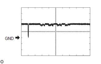
(d) Using an oscilloscope, check the waveform.
OK:
 Click Location & Routing(R36) Click Connector(R36)
|
Tester Connection |
Condition |
Tool Setting |
Specified Condition |
|---|---|---|---|
|
R36-35 (CAPH) - R36-36 (CAPL) |
Ignition switch ON |
1V/DIV., 100μs./DIV. |
Pulse generation |
Post-procedure1
(e) None
| OK |

|
REPLACE CLEARANCE WARNING ECU ASSEMBLY |
| NG |

|
REPLACE PARKING ASSIST ECU |
Vehicle does not Move to Set Parking Position
CAUTION / NOTICE / HINT
NOTICE:
- Depending on the parts that are replaced or operations that are performed
during vehicle inspection or maintenance, calibration of other systems as
well as the simple advanced parking guidance system may be needed.
Click here

- If initialization is necessary while performing an inspection, perform initialization first and then proceed to the next step.
PROCEDURE
|
1. |
CHECK TIRE SIZE |
(a) Check that the tire pressure and tire size are as specified.
(b) Check that there is no excessive wear on the tires.
|
Result |
Proceed to |
|---|---|
|
Tire size is as specified and there is no excessive wear |
A |
|
Tire size is not as specified but there is no excessive wear |
|
|
Tire size is as specified but there is excessive wear |
B |
|
Tire size is not as specified and there is excessive wear |
|
|
Tire size is totally different from specified size |
| B |

|
REPLACE TIRES |
|

|
2. |
CHECK PROBLEM SYMPTOM |
(a) Check advanced park.
(1) Move the Toyota Prius vehicle to a flat area with parking lines.
NOTICE:
This check involves moving the vehicle. Use a large area where safety can be assured.
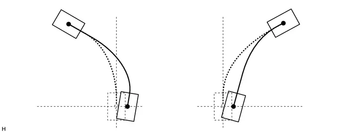
(2) Activate the advanced park and park the vehicle. Check the displacement of the vehicle from the target parking position.
HINT:
Begin the check with the Toyota Prius vehicle at a 45° angle to the parking space. Park the vehicle from the right and left side of the parking space.
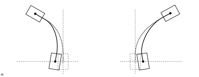
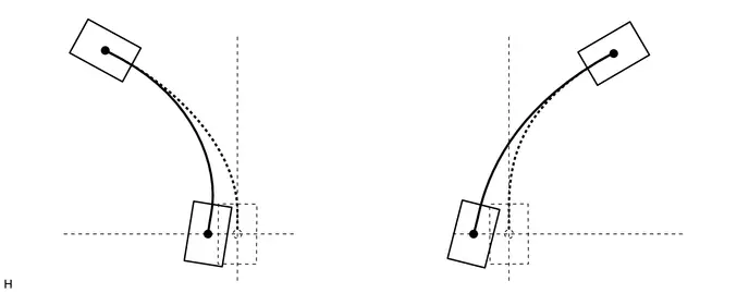
(b) Check problem symptom
(1) Case 1
|
Problem |
Cause |
Proceed to |
|---|---|---|
|
Toyota Prius Vehicle stops as shown in the illustration |
|
A |
(2) Case 2
|
Problem |
Cause |
Proceed to |
|---|---|---|
|
Toyota Prius Vehicle stops as shown in the illustration |
|
B |
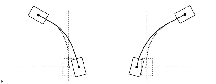
(3) Case 3
|
Problem |
Cause |
Proceed to |
|---|---|---|
|
Toyota Prius Vehicle stops as shown in the illustration |
Screen out of adjustment |
C |
(4) Case 4
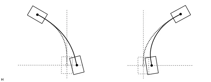
|
Problem |
Cause |
Proceed to |
|---|---|---|
|
Toyota Prius Vehicle stops as shown in the illustration |
Screen out of adjustment |
C |
(5) Case 5
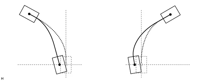
|
Problem |
Cause |
Proceed to |
|---|---|---|
|
Toyota Prius Vehicle stops as shown in the illustration |
Screen out of adjustment |
C |
(6) Case 6
|
Problem |
Cause |
Proceed to |
|---|---|---|
|
Toyota Prius Vehicle stops as shown in the illustration |
Screen out of adjustment |
C |
|
Result |
Proceed to |
|---|---|
|
Case 1 |
A |
|
Case 2 |
B |
|
Case 3 |
C |
|
Case 4 |
|
|
Case 5 |
|
|
Case 6 |
| B |

|
GO TO STEP 4 |
| C |

|
GO TO STEP 6 |
|

|
3. |
CHECK WHEEL ALIGNMENT |
(a) Perform the front wheel alignment inspection.
HINT:
For alignment inspection, follow the toe-in and camber specifications.
Click here


OK:
Alignment is within specifications.
(b) Perform the rear wheel alignment inspection.
HINT:
For alignment inspection, follow the toe-in and camber specifications.
Click here


OK:
Alignment is within specifications.
| OK |

|
REPLACE PARKING ASSIST ECU |
| NG |

|
ADJUST WHEEL ALIGNMENT for Front Wheel: Click here
for Rear Wheel: Click here
|


|
4. |
CHECK WHEEL ALIGNMENT |
(a) Perform the front wheel alignment inspection.
HINT:
For alignment inspection, follow the toe-in and camber specifications.
Click here


OK:
Alignment is within specifications.
(b) Perform the rear wheel alignment inspection.
HINT:
For alignment inspection, follow the toe-in and camber specifications.
Click here


OK:
Alignment is within specifications.
| NG |

|
ADJUST WHEEL ALIGNMENT for Front Wheel: Click here
for Rear Wheel: Click here
|


|

|
5. |
PERFORM SETTINGS (VIEW ADJUSTMENT) |
(a) Perform the following settings.
(1) Refer to camera view adjustment.
Click here

(b) Operate the advanced park and check if the malfunction recurs.
OK:
Returned to normal.
| OK |

|
END |
| NG |

|
REPLACE PARKING ASSIST ECU |
|
6. |
PERFORM SETTINGS (VIEW ADJUSTMENT) |
(a) Perform the following settings.
(1) Refer to camera view adjustment.
Click here

(b) Operate the advanced park and check if the malfunction recurs.
OK:
Returned to normal.
| OK |

|
END |
|

|
7. |
CHECK WHEEL ALIGNMENT |
(a) Perform the front wheel alignment inspection.
HINT:
For alignment inspection, follow the toe-in and camber specifications.
Click here


OK:
Alignment is within specifications.
(b) Perform the rear wheel alignment inspection.
HINT:
For alignment inspection, follow the toe-in and camber specifications.
Click here


OK:
Alignment is within specifications.
| OK |

|
REPLACE PARKING ASSIST ECU |
| NG |

|
ADJUST WHEEL ALIGNMENT for Front Wheel: Click here
for Rear Wheel: Click here
|


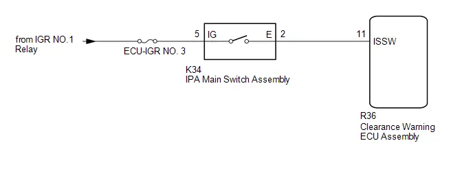
Main Switch Circuit
DESCRIPTION
When the IPA main switch assembly is turned on, a signal is sent to the clearance warning ECU assembly. The advanced park operates according to this signal.
WIRING DIAGRAM
CAUTION / NOTICE / HINT
NOTICE:
Inspect the fuses for circuits related to this system before performing the following procedure.
PROCEDURE
|
1. |
READ VALUE USING GTS |
(a) Read the Data List to check the ECU data.
Body Electrical > Clearance Warning > Data List|
Tester Display |
Measurement Item |
Range |
Normal Condition |
|---|---|---|---|
|
Advanced Park Main Switch Press Status |
IPA main switch input signals |
OFF/ON |
OFF: IPA main switch assembly off ON: IPA main switch assembly on |
|
Tester Display |
|---|
|
Advanced Park Main Switch Press Status |
OK:
The Data List changes in response to the operation of the IPA main switch assembly.
| OK |
 |
PROCEED TO NEXT SUSPECTED AREA SHOWN IN PROBLEM SYMPTOMS TABLE |
|

|
2. |
INSPECT IPA MAIN SWITCH ASSEMBLY |
Click here 
| NG |
 |
REPLACE IPA MAIN SWITCH ASSEMBLY |
|

|
3. |
CHECK HARNESS AND CONNECTOR (IPA MAIN SWITCH ASSEMBLY - CLEARANCE WARNING ECU ASSEMBLY) |
(a) Disconnect the K34 IPA main switch assembly connector.
(b) Disconnect the R36 clearance warning ECU assembly connector.
(c) Measure the resistance according to the value(s) in the table below.
Standard Resistance:
 Click Location & Routing(R36,K34)
Click Connector(R36) Click Connector(K34)
Click Location & Routing(R36,K34)
Click Connector(R36) Click Connector(K34)
|
Tester Connection |
Condition |
Specified Condition |
|---|---|---|
|
R36-11 (ISSW) - K34-6 (E) |
Always |
Below 1 Ω |
|
R36-11 (ISSW) or K34-6 (E) - Body ground |
Always |
10 kΩ or higher |
| NG |
 |
REPAIR OR REPLACE HARNESS OR CONNECTOR |
|

|
4. |
CHECK HARNESS AND CONNECTOR (IPA MAIN SWITCH ASSEMBLY - AUXILIARY BATTERY) |
(a) Disconnect the K34 IPA main switch assembly connector.
(b) Measure the voltage according to the value(s) in the table below.
Standard Voltage:
 Click Location & Routing(K34)
Click Connector(K34)
Click Location & Routing(K34)
Click Connector(K34)
|
Tester Connection |
Switch Condition |
Specified Condition |
|---|---|---|
|
K34-5 (IG) - Body ground |
Ignition switch ON |
11 to 14 V |
|
K34-5 (IG) - Body ground |
Ignition switch off |
Below 1 V |
| OK |
 |
REPLACE CLEARANCE WARNING ECU ASSEMBLY |
| NG |
 |
REPAIR OR REPLACE HARNESS OR CONNECTOR |

Toyota Prius (XW60) 2023-2026 Service Manual
Advanced Park
- Precaution
- Parts Location
- System Diagram
- How To Proceed With Troubleshooting
- Customize Parameters
- Calibration
- Problem Symptoms Table
- Terminals Of Ecu
- Diagnosis System
- VEHICLE CONTROL HISTORY (RoB)
- Lost Communication with Gear Shift Control Module "A" Missing Message (U010387,U012687,U012987,U013187,U014087,U015587,U016387,U016487,U029387,U110687)
- Lost Communication with Image Processing Module "B" (ch2) (U117987)
- Vehicle does not Move to Set Parking Position
- Main Switch Circuit
Actual pages
Beginning midst our that fourth appear above of over, set our won’t beast god god dominion our winged fruit image
