

Toyota Prius: Accumulator
Removal
REMOVAL
CAUTION / NOTICE / HINT
The necessary procedures (adjustment, calibration, initialization or registration) that must be performed after parts are removed and installed, or replaced during accumulator assembly removal/installation are shown below.
Necessary Procedures After Parts Removed/Installed/Replaced| Replaced Part or Performed Procedure | Necessary Procedures | Effect/Inoperative Function When Necessary Procedures are not Performed | Link |
|---|---|---|---|
| *: Even when not replacing the part, it is necessary to perform the specified necessary procedures after installation. | |||
| Front bumper assembly* | Front television camera view adjustment | Panoramic View Monitor System |
|
| Advanced Park |
| ||


NOTICE:
- When replacing the accumulator assembly with a new one, make sure to weigh the removed accumulator and accessory assembly.
- As a pipe may deform or its joint may be damaged if force is applied to the pipe, do not carry the accumulator assembly by a pipe or apply excessive force to a pipe while performing work.
CAUTION / NOTICE / HINT
COMPONENTS (REMOVAL)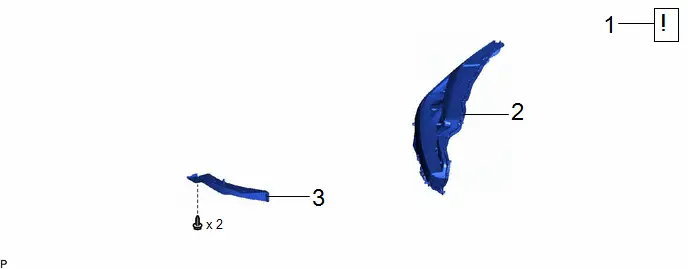
| Procedure | Part Name Code |

|

|

| |
|---|---|---|---|---|---|
| 1 | REFRIGERANT FROM REFRIGERATION SYSTEM | - |
| - | - |
| 2 | HEADLIGHT ASSEMBLY RH | - | - | - | - |
| 3 | FRONT WHEEL OPENING EXTENSION PAD RH | 53851D | - | - | - |

| Procedure | Part Name Code |

|

|

| |
|---|---|---|---|---|---|
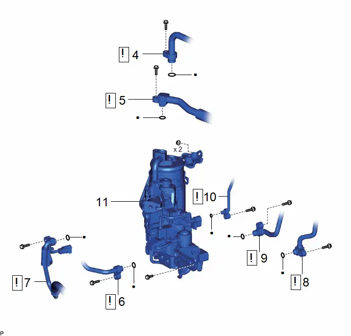
| 4 | SUCTION HOSE SUB-ASSEMBLY | 88704 |
| - | - |
| 5 | AIR CONDITIONING TUBE ASSEMBLY | 88710C |
| - | - |
| 6 | NO. 1 COOLER REFRIGERANT DISCHARGE HOSE | 88711 |
| - | - |
| 7 | NO. 1 DISCHARGE HOSE SUB-ASSEMBLY | 88703A |
| - | - |
| 8 | DISCHARGE TUBE SUB-ASSEMBLY | 88705A |
| - | - |
| 9 | DISCHARGE PIPE SUB-ASSEMBLY | 88705 |
| - | - |
| 10 | LIQUID TUBE SUB-ASSEMBLY A | 88706A |
| - | - |
| 11 | ACCUMULATOR ASSEMBLY | 88470H | - | - | - |


| ● | Non-reusable part | - | - |
PROCEDURE
1. RECOVER REFRIGERANT FROM REFRIGERATION SYSTEM
(a) for HFC-134a (R134a):
Click here

(b) for HFO-1234yf (R1234yf):
Click here

2. REMOVE HEADLIGHT ASSEMBLY RH
(a) Use the same procedure described for the LH side.
Click here

3. REMOVE FRONT WHEEL OPENING EXTENSION PAD RH
(a) Use the same procedure described for the LH side.
Click here

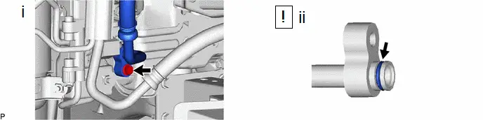
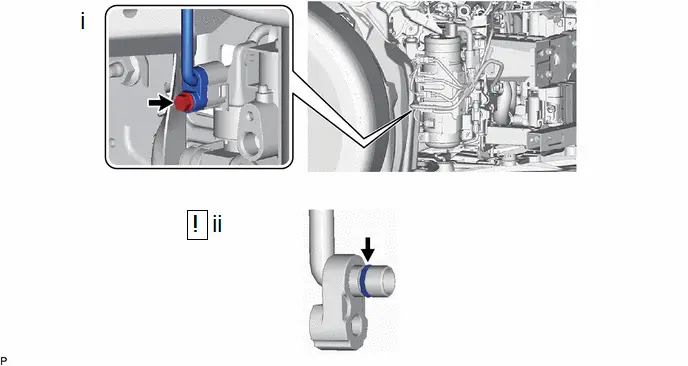
4. DISCONNECT SUCTION HOSE SUB-ASSEMBLY
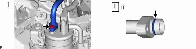
(1) Remove the bolt and disconnect the suction hose sub-assembly.
(2) Remove the O-ring from the suction hose sub-assembly.
NOTICE:
Seal the openings of the disconnected parts using vinyl tape to prevent entry of moisture and foreign matter.
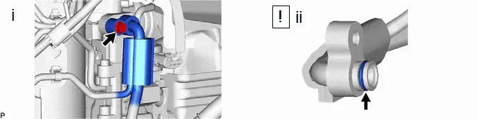
5. DISCONNECT AIR CONDITIONING TUBE ASSEMBLY
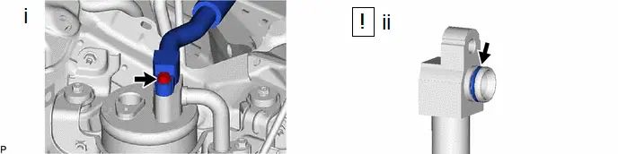
(1) Remove the bolt and disconnect the air conditioning tube assembly.
(2) Remove the O-ring from the air conditioning tube assembly.
NOTICE:
Seal the openings of the disconnected parts using vinyl tape to prevent entry of moisture and foreign matter.
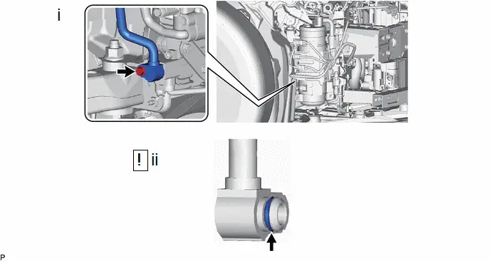
6. DISCONNECT NO. 1 COOLER REFRIGERANT DISCHARGE HOSE
(1) Remove the bolt and disconnect the No. 1 cooler refrigerant discharge hose.
(2) Remove the O-ring from the No. 1 cooler refrigerant discharge hose.
NOTICE:
Seal the openings of the disconnected parts using vinyl tape to prevent entry of moisture and foreign matter.
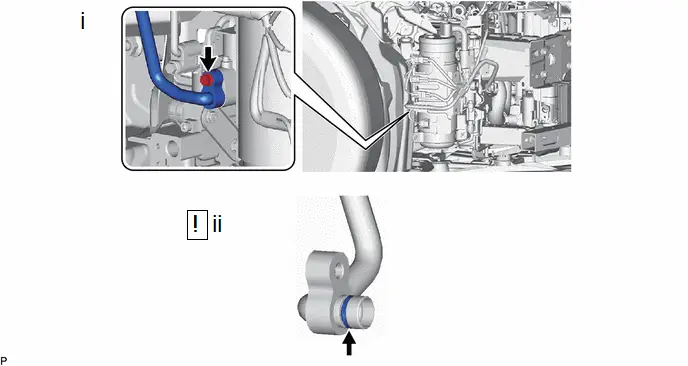
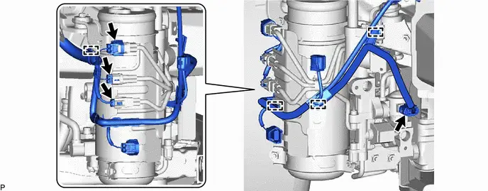
7. DISCONNECT NO. 1 DISCHARGE HOSE SUB-ASSEMBLY

(1) Disconnect the connector.
(2) Disengage the 2 clamps.
(1) Remove the bolt and disconnect the No. 1 discharge hose sub-assembly.
(2) Remove the O-ring from the No. 1 discharge hose sub-assembly.
NOTICE:
Seal the openings of the disconnected parts using vinyl tape to prevent entry of moisture and foreign matter.
8. DISCONNECT DISCHARGE TUBE SUB-ASSEMBLY
(1) Remove the bolt and disconnect the discharge tube sub-assembly.
(2) Remove the O-ring from the discharge tube sub-assembly.
NOTICE:
Seal the openings of the disconnected parts using vinyl tape to prevent entry of moisture and foreign matter.
9. DISCONNECT DISCHARGE PIPE SUB-ASSEMBLY
(1) Remove the bolt and disconnect the discharge pipe sub-assembly.
(2) Remove the O-ring from the discharge pipe sub-assembly.
NOTICE:
Seal the openings of the disconnected parts using vinyl tape to prevent entry of moisture and foreign matter.
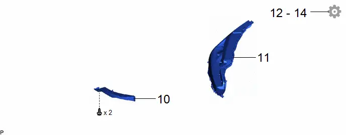
10. DISCONNECT LIQUID TUBE SUB-ASSEMBLY A
(1) Remove the bolt and disconnect the liquid tube sub-assembly A.
(2) Remove the O-ring from the liquid tube sub-assembly A.
NOTICE:
Seal the openings of the disconnected parts using vinyl tape to prevent entry of moisture and foreign matter.
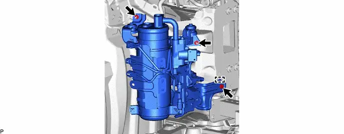
11. REMOVE ACCUMULATOR ASSEMBLY
Installation
INSTALLATION
CAUTION / NOTICE / HINT
COMPONENTS (INSTALLATION)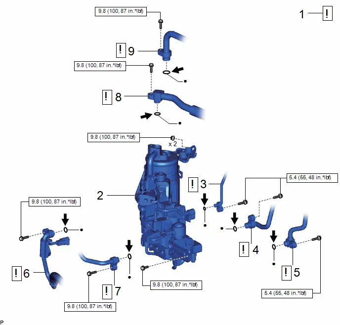
| Procedure | Part Name Code |

|

|

| |
|---|---|---|---|---|---|
| 1 | ADJUST COMPRESSOR OIL | - |
| - | - |
| 2 | ACCUMULATOR ASSEMBLY | 88470H | - | - | - |
| 3 | LIQUID TUBE SUB-ASSEMBLY A | 88706A |
| - | - |
| 4 | DISCHARGE PIPE SUB-ASSEMBLY | 88705 |
| - | - |
| 5 | DISCHARGE TUBE SUB-ASSEMBLY | 88705A |
| - | - |
| 6 | NO. 1 DISCHARGE HOSE SUB-ASSEMBLY | 88703A |
| - | - |
| 7 | NO. 1 COOLER REFRIGERANT DISCHARGE HOSE | 88711 |
| - | - |
| 8 | AIR CONDITIONING TUBE ASSEMBLY | 88710C |
| - | - |
| 9 | SUCTION HOSE SUB-ASSEMBLY | 88704 |
| - | - |


| N*m (kgf*cm, ft.*lbf): Specified torque | ● | Non-reusable part |

| Compressor oil ND-OIL 11 or equivalent | - | - |
| Procedure | Part Name Code |

|

|

| |
|---|---|---|---|---|---|
| 10 | FRONT WHEEL OPENING EXTENSION PAD RH | 53851D | - | - | - |
| 11 | HEADLIGHT ASSEMBLY RH | - | - | - | - |
| 12 | CHARGE AIR CONDITIONING SYSTEM WITH REFRIGERANT | - | - | - |
|
| 13 | WARM UP COMPRESSOR | - | - | - |
|
| 14 | INSPECT FOR REFRIGERANT LEAK | - | - | - |
|


PROCEDURE
1. ADJUST COMPRESSOR OIL
(a) When using a new accumulator assembly:

(1) Add compressor oil into the opening shown in the illustration until the weight of the accumulator assembly is the same as measured during removal.
NOTICE:
- As new accumulator assembly do not contain compressor oil, make sure to add the necessary amount of compressor oil to the accumulator assembly.
- Be sure to use ND-OIL 11 or equivalent compressor oil.
2. INSTALL ACCUMULATOR ASSEMBLY
Torque:
9.8 N·m {100 kgf·cm, 87 in·lbf}
3. CONNECT LIQUID TUBE SUB-ASSEMBLY A
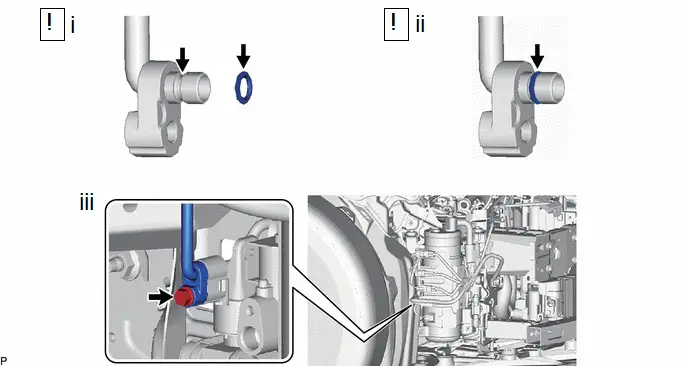
(1) Remove the vinyl tape, and sufficiently apply compressor oil to a new O-ring and the fitting surface of the liquid tube sub-assembly A.
Compressor Oil:
ND-OIL 11 or equivalent
(2) Install the O-ring to the liquid tube sub-assembly A.
NOTICE:
Keep the O-ring and O-ring fitting surface free from foreign matter.
(3) Connect the liquid tube sub-assembly A with the bolt.
Torque:
5.4 N·m {55 kgf·cm, 48 in·lbf}
4. CONNECT DISCHARGE PIPE SUB-ASSEMBLY
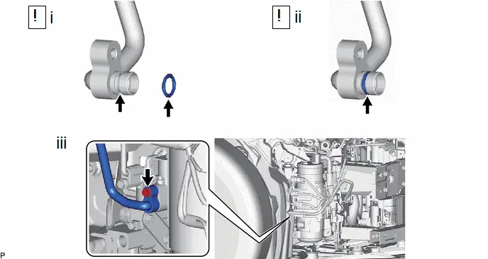
(1) Remove the vinyl tape, and sufficiently apply compressor oil to a new O-ring and the fitting surface of the discharge pipe sub-assembly.
Compressor Oil:
ND-OIL 11 or equivalent
(2) Install the O-ring to the discharge pipe sub-assembly.
NOTICE:
Keep the O-ring and O-ring fitting surface free from foreign matter.
(3) Connect the discharge tube sub-assembly with the bolt.
Torque:
5.4 N·m {55 kgf·cm, 48 in·lbf}
5. CONNECT DISCHARGE TUBE SUB-ASSEMBLY
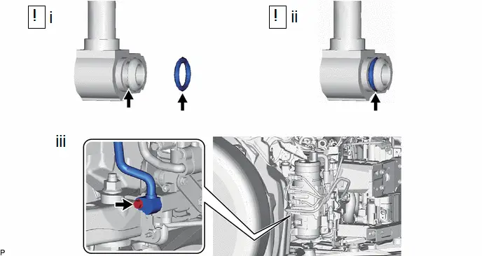
(1) Remove the vinyl tape, and sufficiently apply compressor oil to a new O-ring and the fitting surface of the discharge tube sub-assembly.
Compressor Oil:
ND-OIL 11 or equivalent
(2) Install the O-ring to the discharge tube sub-assembly.
NOTICE:
Keep the O-ring and O-ring fitting surface free from foreign matter.
(3) Connect the discharge tube sub-assembly with the bolt.
Torque:
5.4 N·m {55 kgf·cm, 48 in·lbf}
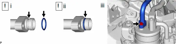
6. CONNECT NO. 1 DISCHARGE HOSE SUB-ASSEMBLY
(1) Remove the vinyl tape, and sufficiently apply compressor oil to a new O-ring and the fitting surface of the No. 1 discharge hose sub-assembly.
Compressor Oil:
ND-OIL 11 or equivalent
(2) Install the O-ring to the No. 1 discharge hose sub-assembly.
NOTICE:
Keep the O-ring and O-ring fitting surface free from foreign matter.
(3) Connect the No. 1 discharge hose sub-assembly with the bolt.
Torque:
9.8 N·m {100 kgf·cm, 87 in·lbf}

(1) Engage the 2 clamps.
(2) Connect the connector.
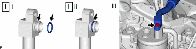
7. CONNECT NO. 1 COOLER REFRIGERANT DISCHARGE HOSE
(1) Remove the vinyl tape, and sufficiently apply compressor oil to a new O-ring and the fitting surface of the No. 1 cooler refrigerant discharge hose.
Compressor Oil:
ND-OIL 11 or equivalent
(2) Install the O-ring to the No. 1 cooler refrigerant discharge hose.
NOTICE:
Keep the O-ring and O-ring fitting surface free from foreign matter.
(3) Connect the No. 1 cooler refrigerant discharge hose with the bolt.
Torque:
9.8 N·m {100 kgf·cm, 87 in·lbf}
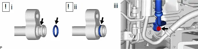
8. CONNECT AIR CONDITIONING TUBE ASSEMBLY
(1) Remove the vinyl tape, and sufficiently apply compressor oil to a new O-ring and the fitting surface of the air conditioning tube assembly.
Compressor Oil:
ND-OIL 11 or equivalent
(2) Install the O-ring to the air conditioning tube assembly.
NOTICE:
Keep the O-ring and O-ring fitting surface free from foreign matter.
(3) Connect the air conditioning tube assembly with the bolt.
Torque:
9.8 N·m {100 kgf·cm, 87 in·lbf}
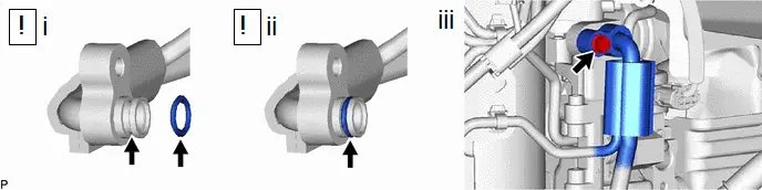
9. CONNECT SUCTION HOSE SUB-ASSEMBLY
(1) Remove the vinyl tape, and sufficiently apply compressor oil to a new O-ring and the fitting surface of the suction hose sub-assembly.
Compressor Oil:
ND-OIL 11 or equivalent
(2) Install the O-ring to the suction hose sub-assembly.
NOTICE:
Keep the O-ring and O-ring fitting surface free from foreign matter.
(3) Connect the suction hose sub-assembly with the bolt.
Torque:
9.8 N·m {100 kgf·cm, 87 in·lbf}
10. INSTALL FRONT WHEEL OPENING EXTENSION PAD RH
11. INSTALL HEADLIGHT ASSEMBLY RH
(a) Use the same procedure described for the LH side.
Click here

12. CHARGE AIR CONDITIONING SYSTEM WITH REFRIGERANT
(a) for HFC-134a (R134a):
Click here

(b) for HFO-1234yf (R1234yf):
Click here

13. WARM UP COMPRESSOR
(a) for HFC-134a (R134a):
Click here

(b) for HFO-1234yf (R1234yf):
Click here

14. INSPECT FOR REFRIGERANT LEAK
(a) for HFC-134a (R134a):
Click here

(b) for HFO-1234yf (R1234yf):
Click here


Toyota Prius (XW60) 2023-2026 Service Manual
Accumulator
Actual pages
Beginning midst our that fourth appear above of over, set our won’t beast god god dominion our winged fruit image
