

Toyota Prius: Accessory Power Outlet System
- Precaution
- Parts Location
- System Diagram
- System Description
- How To Proceed With Troubleshooting
- Problem Symptoms Table
- Terminals Of Ecu
- Data List / Active Test
- Indicator does not Illuminate when Accessory Power Outlet System Main Switch Operated
- Accessory Power Outlet System does not Operate
Precaution
PRECAUTION
PRECAUTION FOR DISCONNECTING CABLE FROM NEGATIVE AUXILIARY BATTERY TERMINAL
NOTICE:
After the ignition switch is turned off, there may be a waiting time before disconnecting the negative (-) auxiliary battery terminal.
Click here

HINT:
When disconnecting and reconnecting the auxiliary battery, there is an automatic learning function that completes learning when the respective system is used.
Click here

PRECAUTIONS WHEN INSPECTING HYBRID CONTROL SYSTEM
Click here

PRECAUTIONS WHEN INSPECTING ACCESSORY POWER OUTLET SYSTEM
(a) When a device connected to the accessory power outlet system does not operate, refer to the owner's manual of the device and confirm that the device can be powered by the accessory power outlet system.
(b) Make sure that all devices connected across all accessory power outlets (AC120 V/1500 W) have a maximum combined power consumption of 1500 W or less.
(c) If the temperature inside the Toyota Prius vehicle is high, the accessory power outlet system may stop power output due to operation of the over-heat protection circuit.
HINT:
To restart power output, use the air conditioning system to sufficiently ventilate or cool the interior, and then press the power outlet switch again.
(d) Even if the hybrid control system is not malfunctioning, the fail-safe function operates and the electric Toyota Prius vehicle charger assembly sends an operation prohibition signal to stop power output if any of the following conditions are met:
- The HV battery SOC is low.
- The HV battery temperature is low or high.
- The HV battery voltage is low.
- AC output current is leaking
(e) When the power output stop is not caused by leakage, it is possible to use the power outlet sockets after clearing the cause by turning the power outlet switch on again.
HINT:
When a power output stop is caused by leakage, it is possible to use the power outlet sockets after clearing the cause by turning the ignition switch off and then to ON (READY), and then turning the power outlet switch on again.
Parts Location
PARTS LOCATION
ILLUSTRATION
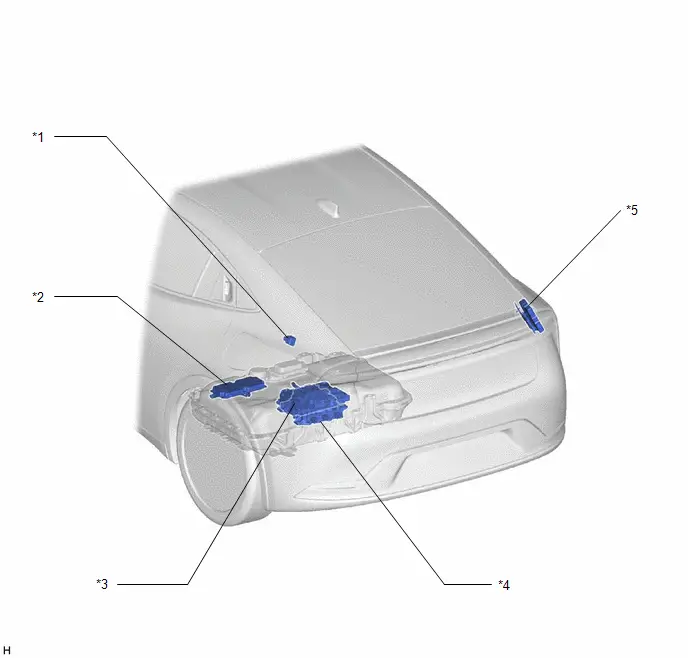
| *1 | REAR NO. 1 POWER OUTLET SOCKET ASSEMBLY | *2 | BATTERY ECU ASSEMBLY |
| *3 | NO. 1 TRACTION BATTERY DEVICE BOX ASSEMBLY | *4 | ELECTRIC Toyota Prius Vehicle CHARGER ASSEMBLY |
| *5 | PLUGIN CHARGE CONTROL ECU ASSEMBLY | - | - |
ILLUSTRATION
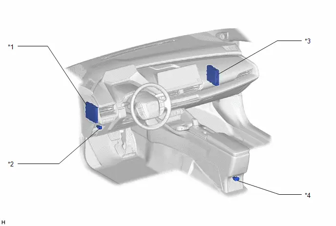
| *1 | CERTIFICATION ECU (SMART KEY ECU ASSEMBLY) | *2 | POWER OUTLET SWITCH |
| *3 | HYBRID Toyota Prius Vehicle CONTROL ECU | *4 | CENTER POWER OUTLET SOCKET ASSEMBLY |
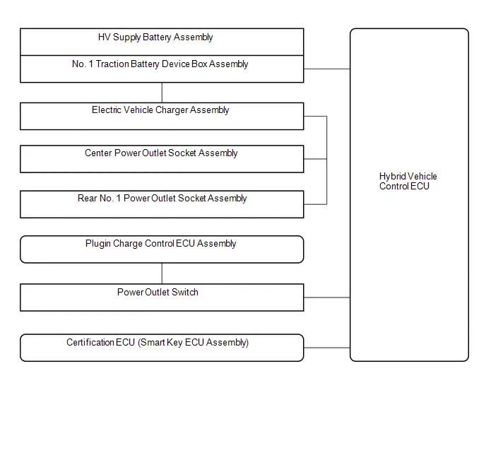
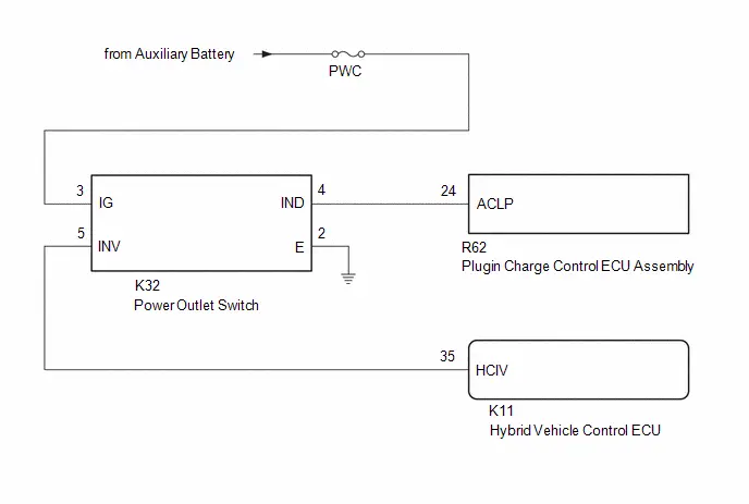
System Diagram
SYSTEM DIAGRAM
System Description
SYSTEM DESCRIPTION
ACCESSORY POWER OUTLET SYSTEM
(a) Accessory Power Outlet System Description
(1) The electric vehicle charger assembly converts voltage from the HV battery to a standard AC120 V (1500 W max) output.
(2) The accessory power outlet system can be operated when the power outlet switch is turned on with the ignition switch ON (READY).
How To Proceed With Troubleshooting
CAUTION / NOTICE / HINT
HINT:
Use the following procedure to troubleshoot the accessory power outlet system.
PROCEDURE
| 1. | VEHICLE BROUGHT TO WORKSHOP |
|

| 2. | CUSTOMER PROBLEM ANALYSIS |
HINT:
- In troubleshooting, confirm that the problem symptoms have been accurately identified. Preconceptions should be discarded in order to make an accurate judgment. To clearly understand what the problem symptoms are, it is extremely important to ask the customer about the problem and the conditions at the time the malfunction occurred.
- Gather as much information as possible for reference. Past problems that seem unrelated may also help in some cases.
-
The following 5 items are important points for problem analysis:
What
Toyota Prius Vehicle model, system name
When
Date, time, occurrence frequency
Where
Road conditions
Under what conditions?
Driving conditions, weather conditions
How did it happen?
Problem symptoms
|

| 3. | PRE-CHECK |
(a) Measure the auxiliary battery voltage with the ignition switch off.
Standard Voltage:
11 to 14 V
If the voltage is below 11 V, recharge or replace the auxiliary battery before proceeding to the next step.
(b) Check the fuses and relays.
(c) Check the connector connections and terminals to make sure that there are no abnormalities such as loose connections, deformation, etc.
|

| 4. | CHECK FOR DTCs |
(a) Using the GTS, check for DTCs.
Powertrain > Hybrid Control > Trouble Codes| Result | Proceed to |
|---|---|
| DTCs are not output | A |
| DTCs are output | B |
| B |

| GO TO HYBRID Toyota Prius Vehicle CONTROL SYSTEM |
|

| 5. | PROBLEM SYMPTOMS TABLE |
(a) Refer to Problem Symptoms Table.
Click here

| Result | Proceed to |
|---|---|
| Fault is not listed in Problem Symptoms Table | A |
| Fault is listed in Problem Symptoms Table | B |
| B |

| GO TO PROBLEM SYMPTOMS TABLE |
|

| 6. | OVERALL ANALYSIS AND TROUBLESHOOTING |
(a) Terminals of ECU.
Click here

(b) Data List.
Click here

|

| 7. | REPAIR OR REPLACE |
|

| 8. | CONFIRMATION TEST |
| NEXT |

| END |
Problem Symptoms Table
PROBLEM SYMPTOMS TABLE
Accessory Power Outlet System| Symptom | Suspected Area | Link |
|---|---|---|
| A device connected to the accessory power outlet system does not operate correctly (device operates correctly using a household power outlet)* | Refer to the owner's manual of the device and confirm that the device can be powered by the accessory power outlet system | - |
| Proceed to "Accessory Power Outlet System does not Operate" |
| |
| A device connected to the accessory power outlet system does not operate correctly (device operates correctly using a household power outlet) | Refer to the owner's manual of the device and confirm that the device can be powered by the accessory power outlet system | - |
| Electric Toyota Prius vehicle charger assembly |
| |
| The indicator does not illuminate even though the accessory power outlet system is operating (accessory power outlet system can still be used correctly) | Proceed to "Indicator does not Illuminate when Accessory Power Outlet System Main Switch Operated" |
|
| The power outlet switch illumination does not illuminate (illumination of other switches illuminate correctly) | Power outlet switch |
|
| Harness or connector | - |


HINT:
*: Symptom for a situation when the combined power consumption of connected devices exceeds 1500W or the Toyota Prius vehicle is malfunctioning.
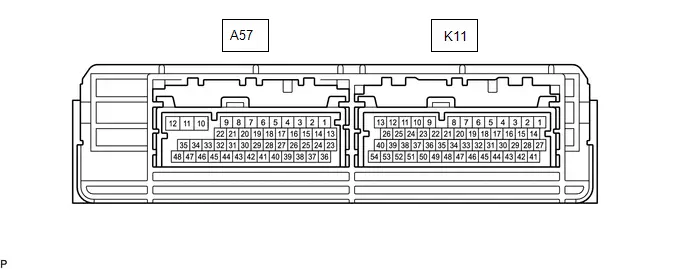
Terminals Of Ecu
TERMINALS OF ECU
ELECTRIC VEHICLE CHARGER ASSEMBLY
(a) Disconnect the R73 electric vehicle charger assembly connector.
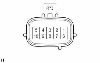
(b) Measure the voltage according to the value(s) in the table below.
| Terminal No. (Symbol) | Terminal Description | Condition | Specified Condition |
|---|---|---|---|
| R73-8 (AMD2) - Body ground | Power source | Ignition switch ON | 11 to 14 V |
| Ignition switch off | Below 1 V |
HYBRID Toyota Prius Vehicle CONTROL ECU
(a) Disconnect the K11 hybrid vehicle control ECU connector.
(b) Measure the voltage according to the value(s) in the table below.
| Terminal No. (Symbol) | Terminal Description | Condition | Specified Condition |
|---|---|---|---|
| K11-35 (HCIV) - Body ground | Activate/Deactivate signal | Ignition switch ON, power outlet switch OFF | 11 to 14 V |
| Ignition switch ON, power outlet switch ON | Below 1 V |
PLUGIN CHARGE CONTROL ECU ASSEMBLY
Click here

Data List / Active Test
DATA LIST / ACTIVE TEST
DATA LIST
(a) Read the Data List according to the display on the GTS.
Powertrain > Hybrid Control > Data List| Tester Display | Measurement Item | Range | Normal Condition | Diagnostic Note |
|---|---|---|---|---|
| AC100V Accessory Outlet Switch | Status of power outlet switch | ON / OFF | ON: Power outlet switch not pushed OFF: Power outlet switch pushed |
|
Indicator does not Illuminate when Accessory Power Outlet System Main Switch Operated
DESCRIPTION
The plugin charge control ECU assembly receives operation signals from the hybrid vehicle control ECU and illuminates the indicator on the power outlet switch.
WIRING DIAGRAM
CAUTION / NOTICE / HINT
NOTICE:
Inspect the fuses for circuits related to this system before performing the following procedure.
PROCEDURE
| 1. | CHECK HARNESS AND CONNECTOR |
| (a) Disconnect the K32 power outlet switch connector. |
|
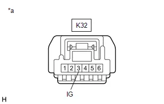
(b) Measure the voltage according to the value(s) in the table below.
Standard Voltage:
 Click Location & Routing(K32) Click Connector(K32)
 | Tester Connection | Condition | Specified Condition |
|---|---|---|
| K32-3 (IG) - Body ground | Ignition switch off | Below 1 V |
| Ignition switch ON | 11 to 14 V |
| NG |

| REPAIR OR REPLACE HARNESS OR CONNECTOR |
|

| 2. | INSPECT POWER OUTLET SWITCH |
Click here

| NG |

| REPLACE POWER OUTLET SWITCH |
|

| 3. | CHECK HARNESS AND CONNECTOR |
(a) Disconnect the K32 power outlet switch connector.
(b) Disconnect the R62 plugin charge control ECU assembly connector.
(c) Measure the resistance according to the value(s) in the table below.
Standard Resistance:
 Click Location & Routing(K32,R62) Click Connector(K32) Click Connector(R62)
 | Tester Connection | Condition | Specified Condition |
|---|---|---|
| K32-4 (IND) - R62-24 (ACLP) | Always | Below 1 Ω |
| K32-4 (IND) or R62-24 (ACLP) - Body ground | Always | 10 kΩ or higher |
| OK |

| REPLACE PLUGIN CHARGE CONTROL ECU ASSEMBLY |
| NG |

| REPAIR OR REPLACE HARNESS OR CONNECTOR |
Accessory Power Outlet System does not Operate
DESCRIPTION
The electric vehicle charger assembly converts DC from the HV battery to AC voltage using the hybrid control system.
When the power outlet switch is ON with the ignition switch ON (READY), household electrical devices up to 1500 W can be used.
WIRING DIAGRAM
CAUTION / NOTICE / HINT
CAUTION:
Precautions for hybrid control system.
Click here

NOTICE:
-
High voltage is supplied to the accessory power outlet system from the HV battery.
Perform the inspections in How to Proceed with Troubleshooting to confirm that there are no malfunctions in the hybrid control system before performing this troubleshooting procedure.
Click here

- Inspect the fuses for circuits related to this system before performing the following procedure.
-
Before replacing the hybrid Toyota Prius vehicle control ECU, refer to Registration.
Click here

HINT:
Even if the hybrid control system is not malfunctioning, the fail-safe function operates depending on the state of the HV battery and hybrid control system, and the hybrid Toyota Prius vehicle control ECU sends an operation prohibition signal to stop power output.
For operation prohibition conditions, refer to

PROCEDURE
| 1. | CHECK DTC OUTPUT (HEALTH CHECK) |
(a) Enter the following menus: Health Check.
(b) Check DTCs.
| Result | Proceed to |
|---|---|
| No DTCs are output | A |
| DTCs are output | B |
(c) Turn the ignition switch off.
| B |

| GO TO DTC CHART |
|

| 2. | CHECK FOR Toyota Prius Vehicle CONTROL HISTORY |
(a) Enter the following menus.
Powertrain > Plug-in Control > Utility| Tester Display |
|---|
| Vehicle Control History (RoB) |
(b) Check for Toyota Prius Vehicle Control History (RoB) except AC Charging History (X10F0).
HINT:
- Vehicle Control History (RoB) items AC Charging History (X10F0) is stored each time plug-in charging is performed, and is also stored when plug-in charging completes without error from start to finish. For this reason, the fact that they are output does not directly indicate any malfunction or problem.
- If AC charging has not started, Toyota Prius Vehicle Control History (RoB) will not be stored.(Except if a power outage occurred before AC charging could start.)
- If Vehicle Control History (RoB) has been stored, it can be determined that AC charging has been performed.
| Result | Proceed to |
|---|---|
| Toyota Prius Vehicle Control History (RoB) not stored | A |
| Vehicle Control History (RoB) stored | B |
(c) Turn the ignition switch off.
| B |

| GO TO Toyota Prius Vehicle CONTROL HISTORY |
|

| 3. | READ VALUE USING GTS |
(a) Confirm that the value of the following Data List item changes correctly in accordance with the operation of the power outlet switch.
Powertrain > Hybrid Control > Data List| Tester Display | Measurement Item | Range | Normal Condition | Diagnostic Note |
|---|---|---|---|---|
| AC100V Accessory Outlet Switch | Power outlet switch | ON / OFF | ON: Power outlet switch not pushed OFF: Power outlet switch pushed | HCIV terminal |
| Tester Display |
|---|
| AC100V Accessory Outlet Switch |
OK:
The Data List item changes correctly in accordance with the operation of the power outlet switch.
| NG |

| GO TO STEP 14 |
|

| 4. | INSPECT CENTER POWER OUTLET SOCKET ASSEMBLY |
Click here

| NG |

| REPLACE CENTER POWER OUTLET SOCKET ASSEMBLY |
|

| 5. | INSPECT REAR NO. 1 POWER OUTLET SOCKET ASSEMBLY |
Click here

| NG |

| REPLACE REAR NO. 1 POWER OUTLET SOCKET ASSEMBLY |
|

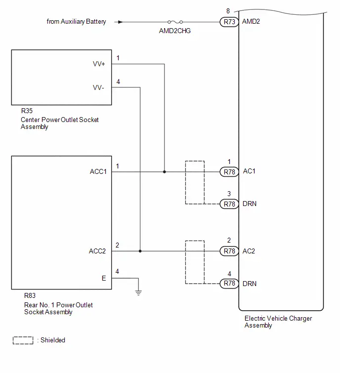
| 6. | CHECK HARNESS AND CONNECTOR (CENTER POWER OUTLET SOCKET ASSEMBLY - ELECTRIC Toyota Prius Vehicle CHARGER ASSEMBLY) |
(a) Disconnect the R78 electric vehicle charger assembly connector.
(b) Disconnect the R35 center power outlet socket assembly connector.
(c) Measure the resistance according to the value(s) in the table below.
Standard Resistance:
 Click Location & Routing(R35,R78) Click Connector(R35) Click Connector(R78)
 | Tester Connection | Condition | Specified Condition |
|---|---|---|
| R35-1 (VV ) - R78-1 (AC1) | Always | Below 1 Ω |
| R35-4 (VV-) - R78-2 (AC2) | Always | Below 1 Ω |
| R35-1 (VV ) or R78-1 (AC1) - Body ground | Always | 10 kΩ or higher |
| R35-4 (VV-) or R78-2 (AC2) - Body ground | Always | 10 kΩ or higher |
| NG |

| REPAIR OR REPLACE HARNESS OR CONNECTOR |
|

| 7. | CHECK HARNESS AND CONNECTOR (REAR NO. 1 POWER OUTLET SOCKET ASSEMBLY - ELECTRIC Toyota Prius Vehicle CHARGER ASSEMBLY) |
(a) Disconnect the R78 electric vehicle charger assembly connector.
(b) Disconnect the R83 rear No. 1 power outlet socket assembly connector.
(c) Measure the resistance according to the value(s) in the table below.
Standard Resistance:
 Click Location & Routing(R83,R78) Click Connector(R83) Click Connector(R78)
 | Tester Connection | Condition | Specified Condition |
|---|---|---|
| R83-1 (ACC1) - R78-1 (AC1) | Always | Below 1 Ω |
| R83-2 (ACC2) - R78-2 (AC2) | Always | Below 1 Ω |
| R83-1 (ACC1) or R78-1 (AC1) - Body ground | Always | 10 kΩ or higher |
| R83-2 (ACC2) or R78-2 (AC2) - Body ground | Always | 10 kΩ or higher |
| NG |

| REPAIR OR REPLACE HARNESS OR CONNECTOR |
|

| 8. | CHECK HARNESS AND CONNECTOR (POWER SOURCE - ELECTRIC Toyota Prius Vehicle CHARGER ASSEMBLY) |
(a) Disconnect the R73 electric vehicle charger assembly connector.
(b) Measure the voltage according to the value(s) in the table below.
Standard Voltage:
 Click Location & Routing(R73) Click Connector(R73)
 | Tester Connection | Condition | Specified Condition |
|---|---|---|
| R73-8 (AMD2) - Body ground | Ignition switch off | Below 1 V |
| Ignition switch ON | 11 to 14 V |
| NG |

| REPAIR OR REPLACE HARNESS OR CONNECTOR |
|

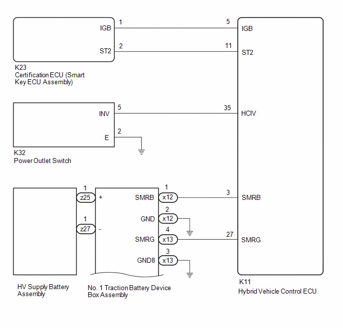
| 9. | CHECK HYBRID Toyota Prius Vehicle CONTROL ECU (Operation signal) |
(a) Connect the K11 hybrid vehicle control ECU connector.
(b) Measure the voltage according to the value(s) in the table below.
Standard Voltage:
 Click Location & Routing(K11) Click Connector(K11)
 | Tester Connection | Condition | Specified Condition |
|---|---|---|
| K11-35 (HCIV) - Body ground |
| 11 V to 14 V |
| Below 1 V |
HINT:
-
Even if the hybrid control system is not malfunctioning, the fail-safe function operates depending on the state of the HV battery and hybrid control system, and the hybrid Toyota Prius vehicle control ECU sends an operation prohibition signal to stop power output.
(For operation prohibition conditions, refer to
 )
) -
If the voltage at terminal K11-35 (HCIV) does not change when the power outlet switch is operated, turn the ignition switch to ON (READY) with the shift lever in P and the accelerator pedal released, and wait for the HV battery SOC to recover. With all recovery conditions met, push the power outlet switch and perform the inspection again.
(For operation prohibition conditions, refer to
 )
) - If the voltage at terminal K11-35 (HCIV) does not change when the power outlet switch assembly is operated again, proceed to "NG".
| NG |

| REPLACE HYBRID Toyota Prius Vehicle CONTROL ECU |
|

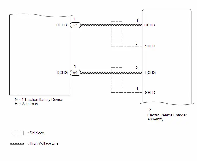
| 10. | CHECK HARNESS AND CONNECTOR (NO. 1 TRACTION BATTERY DEVICE BOX ASSEMBLY - ELECTRIC Toyota Prius Vehicle CHARGER ASSEMBLY) |
(a) Disconnect the w3 and w4 No. 1 traction battery device box assembly connector.
(b) Disconnect the e3 electric vehicle charger assembly connector.
(c) Measure the resistance according to the value(s) in the table below.
Standard Resistance:
 Click Location & Routing(w3,e3,w4) Click Connector(w3) Click Connector(e3) Click Connector(w4)
 | Tester Connection | Condition | Specified Condition |
|---|---|---|
| w3-1 (DCHB) - e3-1 (DCHB) | Always | Below 1 Ω |
| w4-1 (DCHG) - e3-2 (DCHG) | Always | Below 1 Ω |
| w3-1 (DCHB) or e3-1 (DCHB) - Body ground | Always | 10 kΩ or higher |
| w4-1 (DCHG) - e3-2 (DCHG) - Body ground | Always | 10 kΩ or higher |
| NG |

| REPAIR OR REPLACE HARNESS OR CONNECTOR |
|

| 11. | CHECK HARNESS AND CONNECTOR (NO. 1 TRACTION BATTERY DEVICE BOX ASSEMBLY - HYBRID Toyota Prius Vehicle CONTROL ECU) |
(a) Disconnect the x12 and x13 No. 1 traction battery device box assembly connector.
(b) Disconnect the K11 hybrid vehicle control ECU connector.
(c) Measure the resistance according to the value(s) in the table below.
Standard Resistance:
 Click Location & Routing(x12,K11,x13) Click Connector(x12) Click Connector(K11) Click Connector(x13)
 | Tester Connection | Condition | Specified Condition |
|---|---|---|
| x12-1 (SMRB) - K11-3 (SMRB) | Always | Below 1 Ω |
| x12-1 (SMRB) or K11-3 (SMRB) - Body ground | Always | 10 kΩ or higher |
| x13-4 (SMRG) - K11-27 (SMRG) | Always | Below 1 Ω |
| x13-4 (SMRG) or K11-27 (SMRG) - Body ground | Always | 10 kΩ or higher |
| NG |

| REPAIR OR REPLACE HARNESS OR CONNECTOR |
|

| 12. | CHECK HARNESS AND CONNECTOR (NO. 1 TRACTION BATTERY DEVICE BOX ASSEMBLY - BODY GROUND) |
(a) Disconnect the x12 and x13 No. 1 traction battery device box assembly connector.
(b) Measure the resistance according to the value(s) in the table below.
Standard Resistance:
 Click Location & Routing(x12,x13) Click Connector(x12) Click Connector(x13)
 | Tester Connection | Condition | Specified Condition |
|---|---|---|
| x12-2 (GND) - Body ground | Always | Below 1 Ω |
| x13-3 (GND8) - Body ground | Always | Below 1 Ω |
| NG |

| REPAIR OR REPLACE HARNESS OR CONNECTOR |
|

| 13. | INSPECT NO. 1 TRACTION BATTERY DEVICE BOX ASSEMBLY |
Click here

| OK |

| REPLACE HYBRID Toyota Prius Vehicle CONTROL ECU |
| NG |

| REPLACE NO. 1 TRACTION BATTERY DEVICE BOX ASSEMBLY |
| 14. | INSPECT POWER OUTLET SWITCH |
Click here

| NG |

| REPLACE POWER OUTLET SWITCH |
|

| 15. | CHECK HARNESS AND CONNECTOR (POWER OUTLET SWITCH - BODY GROUND) |
| (a) Disconnect the K32 power outlet switch connector. |
|
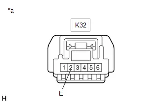
(b) Measure the resistance according to the value(s) in the table below.
Standard Resistance:
 Click Location & Routing(K32) Click Connector(K32)
 | Tester Connection | Condition | Specified Condition |
|---|---|---|
| K32-2 (E) - Body ground | Always | Below 1 Ω |
| NG |

| REPAIR OR REPLACE HARNESS OR CONNECTOR |
|

| 16. | CHECK HARNESS AND CONNECTOR (POWER OUTLET SWITCH - HYBRID Toyota Prius Vehicle CONTROL ECU) |
(a) Disconnect the K32 power outlet switch connector.
(b) Disconnect the K11 hybrid vehicle control ECU connector.
(c) Measure the resistance according to the value(s) in the table below.
Standard Resistance:
 Click Location & Routing(K32,K11) Click Connector(K32) Click Connector(K11)
 | Tester Connection | Condition | Specified Condition |
|---|---|---|
| K32-5 (INV) - K11-35 (HCIV) | Always | Below 1 Ω |
| K32-5 (INV) or K11-35 (HCIV) - Body ground | Always | 10 kΩ or higher |
| OK |

| REPLACE HYBRID Toyota Prius Vehicle CONTROL ECU |
| NG |

| REPAIR OR REPLACE HARNESS OR CONNECTOR |

Toyota Prius (XW60) 2023-2026 Service Manual
Accessory Power Outlet System
- Precaution
- Parts Location
- System Diagram
- System Description
- How To Proceed With Troubleshooting
- Problem Symptoms Table
- Terminals Of Ecu
- Data List / Active Test
- Indicator does not Illuminate when Accessory Power Outlet System Main Switch Operated
- Accessory Power Outlet System does not Operate
Actual pages
Beginning midst our that fourth appear above of over, set our won’t beast god god dominion our winged fruit image
