

Toyota Prius: Wireless Door Lock Control System
- Precaution
- Parts Location
- System Diagram
- How To Proceed With Troubleshooting
- Operation Check
- Customize Parameters
- Problem Symptoms Table
- Terminals Of Ecu
- Data List / Active Test
- Wireless Door Lock Tuner Component Internal Failure (B124296)
- No Answer-Back
Precaution
PRECAUTION
PRECAUTION FOR DISCONNECTING CABLE FROM NEGATIVE (-) AUXILIARY BATTERY TERMINAL
NOTICE:
After the ignition switch is turned off, there may be a waiting time before disconnecting the negative (-) auxiliary battery terminal.
Click here

HINT:
When disconnecting and reconnecting the auxiliary battery, there is an automatic learning function that completes learning when the respective system is used.
Click here


PRECAUTIONS FOR REMOVAL, INSTALLATION AND REPLACEMENT OF COMPONENTS
(a) After replacing certain components, it may be necessary to update the ECU security key.
Click here


PRECAUTIONS WHEN USING GTS
(a) When using the GTS with the ignition switch off, perform lock and unlock operations using the door control switch of the multiplex network master switch assembly at intervals of 1.5 seconds or less until communication between the GTS and the Toyota Prius vehicle begins, and then select the vehicle model manually. Then select Model Code "KEY REGIST" under manual mode and enter the following menus: Body Electrical / Smart Key. While using the GTS, periodically perform lock and unlock operations using the door control switch of the multiplex network master switch assembly at intervals of 1.5 seconds or less to maintain communication between the GTS and the Toyota Prius vehicle.
REPLACEMENT PRECAUTIONS
(a) Before replacing any of the following parts, refer to Registration.
Click here

- Certification ECU (smart key ECU assembly)
- Electrical key transmitter sub-assembly
- Main body ECU (multiplex network body ECU)
(b) Electrical key and tire pressure monitoring system receiver assembly.
(1) When replacing the electrical key and tire pressure monitoring system receiver assembly, read the transmitter IDs (tire pressure warning system) stored in the old ECU using the GTS and write them down before removal.
Click here

(2) If the electrical key and tire pressure monitoring system receiver assembly has been replaced, it is necessary to perform initialization (Click here
 ) after registration (Click here
 ) of the transmitter IDs to the electrical key and tire pressure monitoring system receiver assembly.
PRECAUTIONS FOR ELECTRICAL KEY TRANSMITTER SUB-ASSEMBLY
Click here

NOTICE WHEN CHECKING FOLLOWING
(a) Wireless door lock/unlock function:
This wireless door lock control function operates only when the following 3 conditions are met:
(1) The ignition switch is off.
(2) All of the doors are closed.*
- *: When the Wireless Lock Function with Doors Open customize setting is set to Disable
(3) The power door lock control system is operating properly.
HINT:
The unlock function operates even when a door is open.
(b) The size of the wireless door lock control operation area differs depending on the situation.
(1) The size of the operation area differs depending on the user and the way the electrical key transmitter sub-assembly is held.
(2) In certain areas, the wireless door lock control function will only operate partially for the operation area, which will be reduced due to the Toyota Prius vehicle body shape and the influence of the surrounding environment.
(3) Since the electrical key transmitter sub-assembly uses weak radio waves, strong radio waves or electrical noise in the frequency used by the electrical key transmitter sub-assembly may reduce the size of the operation area and the remote control may not function.
(4) When the transmitter battery is weak, the size of the operation area is reduced and the remote control may not function.
HINT:
- If the electrical key transmitter sub-assembly has been left in a place that is exposed to direct sunlight, such as on the instrument panel, it may cause the battery to be weakened or cause other related problems.
- Do not place the electrical key transmitter sub-assembly near magnetic equipment, such as digital audio players, induction cookers, medical devices that generate low-frequency electromagnetic waves, etc.
(c) Multi channel function
The wireless door lock control system has a multi channel function. Each time the switch on the electrical key transmitter sub-assembly is pressed, the channel is switched alternately between 2 different frequencies and the signal is sent to the electrical key and tire pressure monitoring system receiver assembly.
Parts Location
PARTS LOCATION
ILLUSTRATION
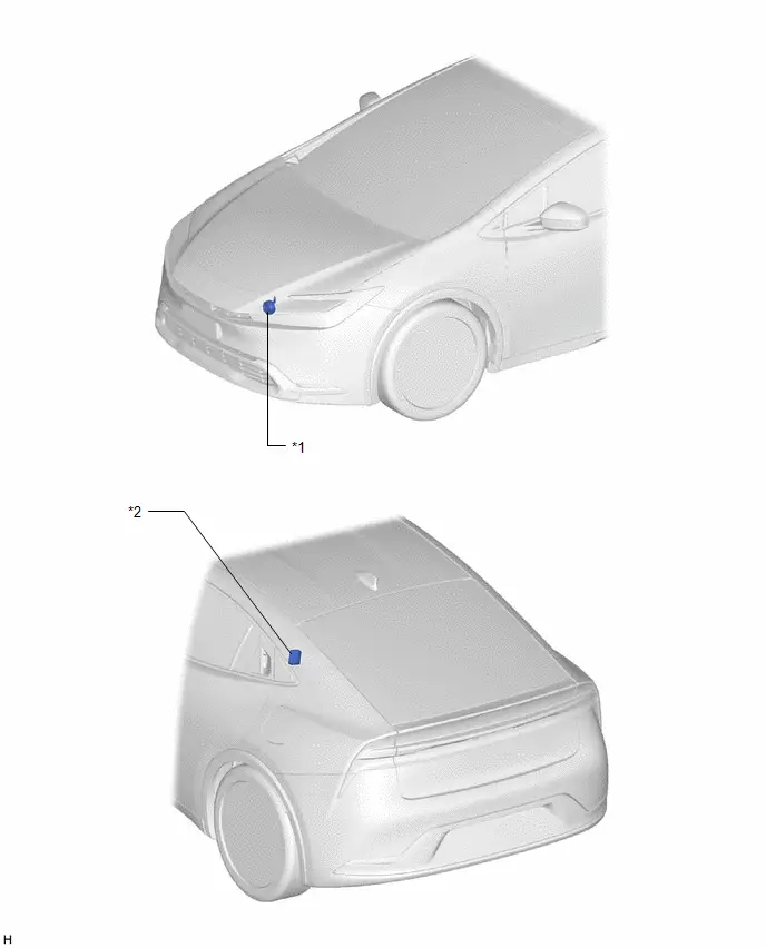
| *1 | WIRELESS DOOR LOCK BUZZER (Toyota Prius Vehicle APPROACHING SPEAKER ASSEMBLY) | *2 | ELECTRICAL KEY AND TIRE PRESSURE MONITORING SYSTEM RECEIVER ASSEMBLY |
ILLUSTRATION
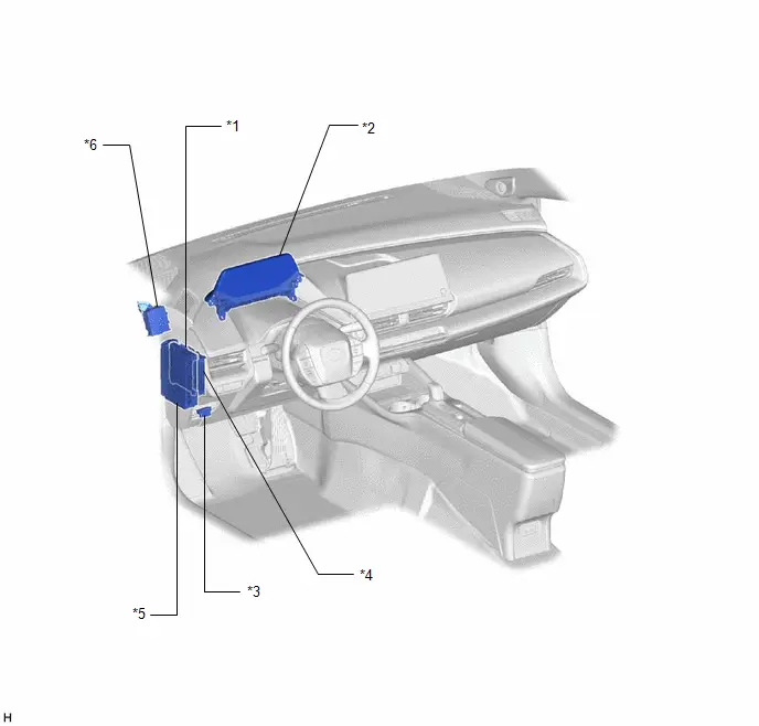
| *1 | MAIN BODY ECU (MULTIPLEX NETWORK BODY ECU) | *2 | COMBINATION METER ASSEMBLY |
| *3 | DLC3 | *4 | CERTIFICATION ECU (SMART KEY ECU ASSEMBLY) |
| *5 | POWER DISTRIBUTION BOX ASSEMBLY | *6 | Toyota Prius Vehicle APPROACHING SPEAKER CONTROLLER |
System Diagram
SYSTEM DIAGRAM
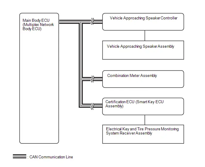
POWER DOOR LOCK CONTROL SYSTEM
Click here

How To Proceed With Troubleshooting
CAUTION / NOTICE / HINT
NOTICE:
Make sure to check the following before proceeding with troubleshooting.
- Do not perform "Smart Code Reset" (all key ID erasure) until the malfunctions and symptoms have been confirmed and resolved. If all key ID erasure is performed without confirming or resolving malfunctions, key registration will be unable to be performed, resulting in unnecessary part replacement.
- Make sure that the smart key system with push-button start has not been disabled by a customize setting.
HINT:
- Replace parts related to the wireless door lock control system and smart key system with push-button start according to the inspection procedure.
- If the wireless door lock control system and smart key system with push-button start do not operate, check the customize setting and make sure that the wireless door lock control system and smart key system with push-button start are not disabled.
-
The wireless door lock control system and smart key system with push-button start primarily use the following systems.
- Wireless door lock control system
- Smart key system (for Entry Function)*
-
Smart key system (for Start Function)
- Immobilizer function
- If 2 or more electrical key transmitter sub-assemblies are registered to the system, make sure to perform troubleshooting with all of them.
- *: w/ Entry Function
PROCEDURE
| 1. | Toyota Prius Vehicle BROUGHT TO WORKSHOP |
(a) Confirm how the vehicle was brought to the workshop.
- Vehicle was driven.
- Vehicle was towed.
HINT:
The cause of the malfunction may be narrowed down by confirming whether the vehicle was driven or towed.
| NEXT |

| GO TO SMART KEY SYSTEM (for Start Function) |
Operation Check
OPERATION CHECK
NOTICE:
Make sure that the vehicle is in an area that allows the wireless control function to operate.
HINT:
- The switches described in this text are the switches for transmitting signals. The switches are built into the electrical key transmitter sub-assembly.
- All the functions listed below must be checked in comparison with the wireless door lock control operation area.
CHECK CUSTOMIZE PARAMETERS
(a) The operation check below is based on the non-customized initial condition of the Toyota Prius vehicle.
Click here

CHECK BASIC FUNCTIONS
(a) Check that the LED of the electrical key transmitter sub-assembly illuminates and turns off 3 times when each switch is pressed and held for 5 seconds.
HINT:
If the transmitter LED illuminates once or twice but not a third time when the switch has been pressed and held for 5 seconds or more, it may have a weak auxiliary battery.
(b) Check that all of the doors lock when the lock switch is pressed.
(c) Check that the driver door unlocks when the unlock switch is pressed once, and all of the doors unlock when pressed twice within 5 seconds.
(d) Check that the back door opens or closes when the power back door switch is pressed and held for 0.8 seconds or more.
CHECK THE CHATTERING PREVENTION FUNCTION
(a) Press and hold the lock or unlock switch on the electrical key transmitter sub-assembly and check that the corresponding operation occurs only once and is not repeated continuously while the switch is held. Then press the switch repeatedly at 1-second intervals, check that the corresponding operation is carried out.
CHECK THE SWITCH OPERATION FAIL-SAFE FUNCTION
(a) Check that the doors cannot be locked/unlocked by operating a switch on an unregistered electrical key transmitter sub-assembly, but that the doors can be locked/unlocked by operating a switch on the registered electrical key transmitter sub-assembly.
CHECK THE AUTOMATIC LOCKING FUNCTION
(a) Check that the doors lock automatically if none of the doors have been opened or all of the doors have not been locked within approximately 60 or 30* seconds of all of the doors being unlocked by pressing the unlock switch.
(b) Check that the automatic locking function does not operate when any door has been opened within approximately 60 or 30* seconds of unlocking the doors by pressing the unlock switch.
(c) Check that the automatic locking function does not operate when all of the doors have been locked manually (such as using key linked operation, or by pressing the lock switch) within approximately 60 or 30* seconds of unlocking the doors by pressing the unlock switch.
- *: Default setting differs depending on the country.
CHECK THE DOOR AJAR WARNING BUZZER FUNCTION
HINT:
When the Wireless Lock Function with Doors Open customize setting is set to Enable, this function will be disabled even if the Open Door Warning Function customize setting is set to Enable.
(a) Check that the wireless door lock buzzer sounds for approximately 5 seconds when the lock switch is pressed with any of the doors ajar or open.
HINT:
The doors can be unlocked even when a door is open or ajar.
CHECK THE DOOR LOCK STOP FUNCTION THAT OPERATES WHEN A DOOR IS OPEN/AJAR
(a) With a door open or ajar, check that the doors cannot be locked by operating the lock switch.
CHECK THE WIRELESS RESERVATION LOCK FUNCTION (w/ Wireless Reservation Lock Function)
HINT:
When the Wireless Lock Function with Doors Open customize setting is set to Enable, the door ajar warning buzzer function will be disabled even if the Open Door Warning Function customize setting is set to Enable.
(a) Check that the doors are locked by performing a wireless lock operation with any door open.
(b) Check that answer-back (wireless door lock buzzer) function operates when the wireless operation is performed and answer-back (hazard warning light) function operates when the doors are closed.
CHECK THE POWER BACK DOOR RESERVATION LOCK FUNCTION
(a) Check that the doors lock after the back door is closed when the lock switch is pressed during the back door closing operation via the power back door function.
CHECK WIRELESS ONE MOTION FUNCTION
Click here

CHECK THE ANSWER-BACK (HAZARD WARNING LIGHT) FUNCTION
(a) When the lock switch is pressed, check that the hazard warning lights flash once simultaneously with the locking operation of all of the doors.
(b) When the unlock switch is pressed and all of the doors are locked, check that the hazard warning lights flash twice simultaneously with the unlocking operation of all of the doors.
(c) With the back door locked, when the back door open switch is pressed and held for 0.8 seconds or more, check that the hazard warning lights flash twice.
CHECK THE ANSWER-BACK (WIRELESS DOOR LOCK BUZZER) FUNCTION
(a) When the lock switch is pressed, check that the buzzer sounds once simultaneously with the locking operation of all of the doors.
(b) When the unlock switch is pressed and all of the doors are locked, check that the buzzer sounds twice simultaneously with the unlocking operation of all of the doors.
(c) With the back door locked, when the back door open switch is pressed and held for 0.8 seconds or more, check that the wireless door lock buzzer sounds.
CHECK THE PANIC ALARM CONTROL FUNCTION (w/ Panic Function)
(a) Check that the horn sounds, the headlights, taillights, hazard lights flash and the interior lights remain on (when the light switch is turned to the door position) for 60 seconds, when the panic switch is held down for 0.8 seconds or more. Also, check that the horn stops sounding and the lights stop flashing when any switch of the electrical key transmitter sub-assembly is pressed.
CHECK THE ILLUMINATED ENTRY FUNCTION
Click here

CHECK THE POWER WINDOW OPERATION FUNCTION
Click here

Customize Parameters
CUSTOMIZE PARAMETERS
CUSTOMIZE WIRELESS DOOR LOCK CONTROL SYSTEM
NOTICE:
- When the customer requests a change in a function, first make sure that the function can be customized.
- Be sure to make a note of the current settings before customizing.
- When troubleshooting a function, first make sure that the function is set to the default setting.
HINT:
The following items can be customized.
(a) Customizing with the GTS
(1) Connect the GTS to the DLC3.
(2) Turn the ignition switch to ON.
(3) Turn the GTS on.
(4) Enter the following menus: Customize Setting / Wireless Door Lock or Door Lock.
(5) Select the setting by referring to the table below.
Wireless Door Lock| Tester Display | Description | Default | Setting | ECU |
|---|---|---|---|---|
| Wireless Buzzer Response Function | Function that enables/disables the wireless door lock buzzer response. | Enable | $00:Disable,$01:Enable | Main body ECU (Multiplex network body ECU) |
| Panic Function | Function that operates the theft deterrent system by pressing the panic switch on the electrical key transmitter sub-assembly for 0.8 seconds.*1 | Enable | $00:Disable,$01:Enable | Main body ECU (Multiplex network body ECU) |
| Hazard Answer Back Function | Function that flashes the hazard warning lights once when the doors are locked by wireless operation and twice when the doors are unlocked by wireless operation. | Enable | $00:Disable,$01:Enable | Main body ECU (Multiplex network body ECU) |
| Wireless Buzzer Volume Setting | Function that adjusts the wireless door lock buzzer volume. | Level5 | $00:Level7(MAX),$01:Level6,$02:Level5,$03:Level4,$04:Level3,$05:Level2,$06:Level1,$07:Level0(MIN) | Main body ECU (Multiplex network body ECU) |
| Wireless Unlock Twice Function | Function that unlocks the driver door when the unlock switch on the electrical key transmitter sub-assembly is pressed once, and unlocks all of the doors when pressed twice. If this setting is OFF, pressing the unlock switch once unlocks all of the doors. | Enable | $00:Disable,$01:Enable | Main body ECU (Multiplex network body ECU) |
| Wireless Lock Function with Doors Open | Function that locks the doors automatically if the lock switch on the electrical key transmitter sub-assembly is pressed with any door open and then all of the doors are closed.*2 | Enable | $00:Disable,$01:Enable | Main body ECU (Multiplex network body ECU) |
- *1: w/ Panic Function
- *2: w/ Wireless Reservation Lock Function
| Tester Display | Description | Default | Setting | ECU |
|---|---|---|---|---|
| Automatic Door Lock Function | Function that turns the automatic locking function on or off.* | Enable | $00:Disable,$01:Enable | Main body ECU (Multiplex network body ECU) |
| Open Door Warning Function | Function that sounds a buzzer when the lock switch is pressed when any of the doors are ajar. | Enable | $00:Disable,$01:Enable | Main body ECU (Multiplex network body ECU) |
| Door Auto Lock Timer Setting | Function that regulates the interval between unlocking and automatic relocking of the doors. | 30sec/60sec* | $00:30sec,$01:60sec,$02:120sec | Main body ECU (Multiplex network body ECU) |
- *: Default setting differs depending on the country.
(b) Customizing with the multi-display
(1) Turn the ignition switch to ON.
(2) Enter the following menus: Settings / Toyota Prius Vehicle customize / Door control.
(3) Select the setting by referring to the table below.
Key settings| Display | Description | Default | Setting | Relevant ECU |
|---|---|---|---|---|
| Auto relock timer | Function that regulates the interval between unlocking and automatic relocking of the doors | 60sec | Off, 30sec, 60sec or 120sec | Main body ECU (Multiplex network body ECU) |
| Feedback lights | Function that flashes the hazard warning lights once when the doors are locked by wireless operation and twice when the doors are unlocked by wireless operation. | On | On or Off | Main body ECU (Multiplex network body ECU) |
| Feedback tone | Function that adjusts the wireless door lock buzzer volume | 5 | Off, 1, 2, 3, 4, 5, 6 or 7 | Main body ECU (Multiplex network body ECU) |
| Display | Description | Default | Setting | Relevant ECU |
|---|---|---|---|---|
| 2-press unlock | Function that unlocks the driver door when the unlock switch on the electrical key transmitter sub-assembly is pressed once, and unlocks all of the doors when pressed twice. If this setting is OFF, pressing the unlock switch once unlocks all of the doors. | Enable | On or Off | Main body ECU (Multiplex network body ECU) |
| Lock when door opened | Function that locks the doors automatically if the lock switch on the electrical key transmitter sub-assembly is pressed with any door open and then all of the doors are closed. | Enable | On or Off | Main body ECU (Multiplex network body ECU) |
Problem Symptoms Table
PROBLEM SYMPTOMS TABLE
HINT:
- Use the table below to help determine the cause of problem symptoms. If multiple suspected areas are listed, the potential causes of the symptoms are listed in order of probability in the "Suspected Area" column of the table. Check each symptom by checking the suspected areas in the order they are listed. Replace parts as necessary.
- Inspect the fuses and relays related to this system before inspecting the suspected areas below.
| Symptom | Suspected Area | Link |
|---|---|---|
| Wireless control function and entry function do not operate | Check DTC output |
|
| Lighting system (INT) | ||
| Power door lock control system | ||
| Wave interference | ||
| Transmitter battery | ||
| Electrical key transmitter sub-assembly | ||
| Wire harness or connector | ||
| Check connector connection | ||
| Electrical key and tire pressure monitoring system receiver assembly | ||
| Certification ECU (Smart key ECU assembly) | ||
| Main body ECU (Multiplex network body ECU) | ||
| B code registration failed | ||
| Wireless control function does not operate but entry function operates | Electrical key transmitter sub-assembly | - |
| Back door does not open when back door open switch operated (Wireless lock/unlock function does not operate)* | Check customize setting (Wireless Unlock Twice Function "Disable") | |
| Power back door system | ||
| Only answer-back function does not operate properly | Check customize setting |
|
| Perform operation check | ||
| Lighting system (INT) | ||
| Main body ECU (Multiplex network body ECU) | ||
| Lighting system (Ext) (Hazard warning switch circuit) | ||
| Wire harness or connector | ||
| Acoustic Toyota Prius vehicle alerting system | ||
| Power distribution box assembly | ||
| Wireless door lock buzzer | ||
| Only automatic lock function does not operate properly | Perform operation check |
|
| Power door lock control system |
| |
| Main body ECU (Multiplex network body ECU) | - | |
| Only illuminated entry function does not operate | Perform operation check |
|
| Lighting system (Int) |
| |
| Main body ECU (Multiplex network body ECU) | - | |
| Only door ajar warning buzzer function does not operate | Main body ECU (Multiplex network body ECU) |
|
| Acoustic Toyota Prius vehicle alerting system |
| |
| Only panic alarm function does not operate | Perform operation check |
|
| Lighting system (Int) (Interior lights) |
| |
| Lighting system (Ext) (Headlights, Taillights, Hazard warning lights) |
| |
| Horn system |
| |
| Main body ECU (Multiplex network body ECU) |
|


- *: W/ Power Back Door System
Terminals Of Ecu
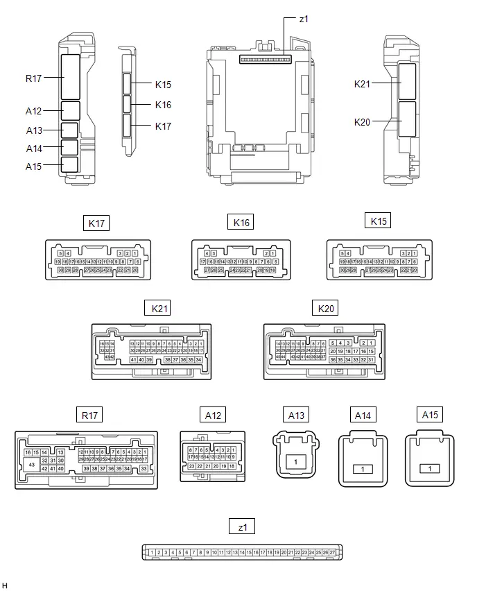
TERMINALS OF ECU
CHECK POWER DISTRIBUTION BOX ASSEMBLY AND MAIN BODY ECU (MULTIPLEX NETWORK BODY ECU)
(a) Remove the main body ECU (multiplex network body ECU) from the power distribution box assembly.
Click here


(b) Reconnect the power distribution box assembly connectors.
(c) Measure the voltage and resistance according to the value(s) in the table below.
| Terminal No. (Symbol) | Terminal Description | Condition | Specified Condition |
|---|---|---|---|
| z1-13 (GND1) - Body ground | Ground | Always | Below 1 Ω |
| z1-14 (GND2) - Body ground | Ground | Always | Below 1 Ω |
| z1-26 (BECU) - Body ground | Auxiliary battery power supply | Ignition switch off | 11 to 14 V |
| z1-27 (IGR) - Body ground | IG power supply | Ignition switch ON | 11 to 14 V |
| Ignition switch off | Below 1 V |
CHECK CERTIFICATION ECU (SMART KEY ECU ASSEMBLY)
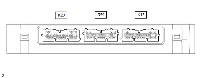
(a) Disconnect the K13 certification ECU (smart key ECU assembly) connector.
(b) Measure the voltage and resistance according to the value(s) in the table below.
HINT:
Measure the values on the wire harness side with the connector disconnected.
| Terminal No. (Symbol) | Terminal Description | Condition | Specified Condition |
|---|---|---|---|
| K13-6 ( B) - K13-29 (E) | Auxiliary battery power supply | Ignition switch off | 11 to 14 V |
| K13-29 (E) - Body ground | Ground | Always | Below 1 Ω |
(c) Reconnect the K13 certification ECU (smart key ECU assembly) connector.
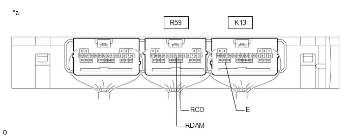
(d) Check for pulses according to the value(s) in the table below.
| Terminal No. (Symbol) | Terminal Description | Condition | Specified Condition |
|---|---|---|---|
| R59-21 (RCO) - K13-29 (E) | Output to electrical key and tire pressure monitoring system receiver assembly (Power supply for electrical key and tire pressure monitoring system receiver assembly. Certification ECU (smart key ECU assembly) outputs 5 V when receiver starts operating.) | Procedure:
| Plus generation (See waveform 1) |
| R59-11 (RDAM) - K13-29 (E) | Electrical key and tire pressure monitoring system receiver assembly communication circuit | Procedure:
| Plus generation (See waveform 2) |
| R59-12 (CSEL) - K13-29 (E) | Communication channel switching circuit | Procedure:
| No pulse generation → Pulse generation |
(e) Using an oscilloscope, check waveform 1.
HINT:
The oscilloscope waveform shown in the illustration is an example for reference only. Noise, chattering, etc. are not shown.
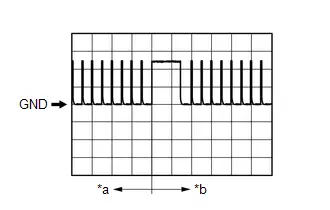
| *a | Before lock or unlock switch of electrical key transmitter sub-assembly pressed |
| *b | After lock or unlock switch of electrical key transmitter sub-assembly pressed |
| Item | Content |
|---|---|
| Tester connection | R59-21 (RCO) - K13-29 (E) |
| Tool setting | 2 V/DIV., 500 ms/DIV. |
| Condition | Procedure:
|
(f) Using an oscilloscope, check waveform 2.
HINT:
The oscilloscope waveform shown in the illustration is an example for reference only. Noise, chattering, etc. are not shown.
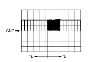
| *a | Before lock or unlock switch of electrical key transmitter sub-assembly pressed |
| *b | After lock or unlock switch of electrical key transmitter sub-assembly pressed |
| Item | Content |
|---|---|
| Tester connection | R59-11 (RDAM) - K13-29 (E) |
| Tool setting | 5 V/DIV., 500 ms/DIV. |
| Condition | Procedure:
|
Data List / Active Test
DATA LIST / ACTIVE TEST
DATA LIST
NOTICE:
In the table below, the values listed under "Normal Condition" are reference values. Do not depend solely on these reference values when deciding whether a part is faulty or not.
HINT:
Using the GTS to read the Data List allows the values or states of switches, sensors, actuators and other items to be read without removing any parts. This non-intrusive inspection can be very useful because intermittent conditions or signals may be discovered before parts or wiring is disturbed. Reading the Data List information early in troubleshooting is one way to save diagnostic time.
(a) Connect the GTS to the DLC3.
(b) Turn the ignition switch to ON.
(c) Turn the GTS on.
(d) Read the Data List according to the display on the GTS.
Body Electrical > Main Body > Data List| Tester Display | Measurement Item | Range | Normal Condition | Diagnostic Note |
|---|---|---|---|---|
| FR Door Lock Position Switch Status | Front door RH lock status | Lock or Unlock | Lock: Front door RH locked Unlock: Front door RH Unlocked | - |
| FL Door Lock Position Switch Status | Front door LH lock status | Lock or Unlock | Lock: Front door LH locked Unlock: Front door LH Unlocked | - |
| RR Door Lock Position Switch Status | Rear door RH lock status | Lock or Unlock | Lock: Rear door RH locked Unlock: Rear door RH Unlocked | - |
| RL Door Lock Position Switch Status | Rear door LH lock status | Lock or Unlock | Lock: Rear door LH locked Unlock: Rear door LH Unlocked | - |
| FR Door Courtesy Switch Status | Front door courtesy light switch signal | Close or Open | Close: Front door RH closed Open: Front door RH open | - |
| FL Door Courtesy Switch Status | Front door courtesy light switch signal | Close or Open | Close: Front door LH closed Open: Front door LH open | - |
| RR Door Courtesy Switch Status | Front door courtesy light switch signal | Close or Open | Close: Rear door RH closed Open: Rear door RH open | - |
| RL Door Courtesy Switch Status | Front door courtesy light switch signal | Close or Open | Close: Rear door LH closed Open: Rear door LH open | - |
| Back Door Courtesy Switch Status | Back door courtesy light switch signal | Close or Open | Close: Back door closed Open: Back door open | - |
| IGR Power | Ignition switch ON signal | Disable or Enable | OFF: Ignition switch off or ACC ON: Ignition switch ON | - |
| Automatic Door Lock Function | Wireless auto lock function | Disable or Enable | Customize setting displayed | - |
| Wireless Buzzer Response Function | Buzzer answer-back of wireless function | Disable or Enable | Customize setting displayed | - |
| Open Door Warning Function | Open door warning | Disable or Enable | Customize setting displayed | - |
| Panic Function | Panic function | Disable or Enable | Customize setting displayed | w/ Panic Function |
| Wireless Unlock Twice Function | 2 press wireless unlock function | Disable or Enable | Customize setting displayed | - |
| Door Auto Lock Timer Setting | Automatic lock time | 30sec, 60sec or 120sec | Customize setting displayed | - |
| Hazard Answer Back Function | Hazard light answer-back of wireless function | Disable or Enable | Customize setting displayed | - |
| Wireless Buzzer Volume Setting | Wireless door lock buzzer volume | Level7(MAX), Level6, Level5, Level4, Level3, Level2, Level1 or Level0(MIN) | Customize setting displayed | - |
| Wireless Lock Function with Doors Open | Wireless reservation lock function | Disable or Enable | Customize setting displayed | w/ Wireless Reservation Lock Function |
ACTIVE TEST
HINT:
Using the GTS to perform Active Tests allows relays, VSVs, actuators and other items to be operated without removing any parts. This non-intrusive functional inspection can be very useful because intermittent operation may be discovered before parts or wiring is disturbed. Performing Active Tests early in troubleshooting is one way to save diagnostic time. Data List information can be displayed while performing Active Tests.
(a) Connect the GTS to the DLC3.
(b) Turn the ignition switch to ON.
(c) Turn the GTS on.
(d) Perform the Active Test according to the display on the GTS.
Body Electrical > Main Body > Active Test| Tester Display | Measurement Item | Control Range | Diagnostic Note |
|---|---|---|---|
| Door Lock | Door lock signal | OFF/ON | - |
| Door Unlock | Door unlock signal | OFF/ON | - |
| D-Door Unlock | Driver door unlock signal | OFF/ON | - |
Wireless Door Lock Tuner Component Internal Failure (B124296)
DESCRIPTION
The electrical key and tire pressure monitoring system receiver assembly is used to receive radio waves related to the entry functions of the electrical key transmitter sub-assembly. The certification ECU (smart key ECU assembly) decodes the requested electrical key transmitter sub-assembly operation by identifying a key code based on the radio waves received via the electrical key and tire pressure monitoring system receiver assembly. The electrical key and tire pressure monitoring system receiver assembly receives a signal from the electrical key transmitter sub-assembly and sends signals to the main body ECU (multiplex network body ECU) through the certification ECU (smart key ECU assembly). (ex. If a door lock operation is requested, the certification ECU (smart key ECU assembly) sends a door lock command to the main body ECU (multiplex network body ECU)).
| DTC No. | Detection Item | DTC Detection Condition | Trouble Area | DTC Output from | Priority |
|---|---|---|---|---|---|
| B124296 | Wireless Door Lock Tuner Component Internal Failure |
|
| Smart Key | A |
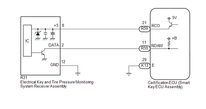
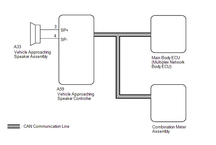
WIRING DIAGRAM
CAUTION / NOTICE / HINT
NOTICE:
- When using the GTS with the ignition switch off, perform lock and unlock operations using the door control switch of the multiplex network master switch assembly at intervals of 1.5 seconds or less until communication between the GTS and the Toyota Prius vehicle begins, and then select the vehicle model manually. Then select Model Code "KEY REGIST" under manual mode and enter the following menus: Body Electrical / Smart Key. While using the GTS, periodically perform lock and unlock operations using the door control switch of the multiplex network master switch assembly at intervals of 1.5 seconds or less to maintain communication between the GTS and the Toyota Prius vehicle.
-
Before replacing the certification ECU (smart key ECU assembly), refer to Registration.
Click here

- When replacing or inspecting the electrical key and tire pressure monitoring system receiver assembly and wire harness, do not change the position or length of the wire harness. If the wire harness is too close to the electrical key and tire pressure monitoring system receiver assembly, the performance of the entry function and wireless function may be affected.
- The detection conditions of this DTC cannot be met within 10 seconds of the ignition switch being turned from off to ON or ON to off.
- Make sure that there are no electrical key transmitter sub-assemblies in the Toyota Prius vehicle.
-
When replacing the electrical key and tire pressure monitoring system receiver assembly, read the transmitter IDs (tire pressure warning system) stored in the old ECU using the GTS and write them down before removal.
Click here

-
If the electrical key and tire pressure monitoring system receiver assembly has been replaced, it is necessary to perform initialization (Click here
 ) after registration (Click here
 ) of the transmitter IDs to the electrical key and tire pressure monitoring system receiver assembly.
PROCEDURE
| 1. | CHECK CERTIFICATION ECU (SMART KEY ECU ASSEMBLY) |
Pre-procedure1
(a) Disconnect the R31 electrical key and tire pressure monitoring system receiver assembly connector.
Procedure1
(b) Measure the voltage and resistance and check for pulses according to the value(s) in the table below.
| *a | Component with harness connected (Certification ECU (Smart Key ECU Assembly)) | - | - |
Standard Resistance:
 Click Location & Routing(K13) Click Connector(K13)
 | Tester Connection | Condition | Specified Condition |
|---|---|---|
| K13-29 (E) - Body ground | Always | Below 1 Ω |
Standard Voltage:
 Click Location & Routing(R59,K13) Click Connector(R59) Click Connector(K13)
 | Tester Connection | Condition | Specified Condition |
|---|---|---|
| R59-11 (RDAM) - K13-29 (E) | Always | 11 to 14 V |
| R59-21 (RCO) - K13-29 (E) | Always | Below 1 V → 4.5 to 5.5 V pulse generation at regular intervals |
Post-procedure1
(c) None
| OK |

| REPLACE ELECTRICAL KEY AND TIRE PRESURE MONITORING SYSTEM RECEIVER ASSEMBLY
|


|

| 2. | CHECK HARNESS AND CONNECTOR (ELECTRICAL KEY AND TIRE PRESURE MONITORING SYSTEM RECEIVER ASSEMBLY - CERTIFICATION ECU (SMART KEY ECU ASSEMBLY) AND BODY GROUND) |
Pre-procedure1
(a) Disconnect the R59 certification ECU (smart key ECU assembly) connector.
Procedure1
(b) Measure the resistance according to the value(s) in the table below.
Standard Resistance:
 Click Location & Routing(R31,R59) Click Connector(R31) Click Connector(R59)
 | Tester Connection | Condition | Specified Condition |
|---|---|---|
| R31-2 (DATA) - R59-11 (RDAM) | Always | Below 1 Ω |
| R31-8 ( 5) - R59-21 (RCO) | Always | Below 1 Ω |
| R31-12 (GND) - Body ground | Always | Below 1 Ω |
| R31-2 (DATA) or R59-11 (RDAM) - Other terminals and body ground | Always | 10 kΩ or higher |
| R31-8 ( 5) or R59-21 (RCO) - Other terminals and body ground | Always | 10 kΩ or higher |
Post-procedure1
(c) None
| OK |

| REPLACE CERTIFICATION ECU (SMART KEY ECU ASSEMBLY)
|


| NG |

| REPAIR OR REPLACE HARNESS OR CONNECTOR |
No Answer-Back
DESCRIPTION
In some cases, wireless door lock control functions are normal but the hazard warning light and wireless door lock buzzer answer-back function do not operate. In such cases, hazard warning light and wireless door lock buzzer signal outputs from the main body ECU (multiplex network body ECU) may be malfunctioning.
WIRING DIAGRAM
CAUTION / NOTICE / HINT
NOTICE:
-
The wireless door lock control system uses the CAN communication system. Inspect the communication function by following How to Proceed with Troubleshooting. Troubleshoot the wireless door lock control system after confirming that the communication system is functioning properly.
Click here

-
Before replacing the main body ECU (multiplex network body ECU), refer to Registration.
Click here

- Before performing the inspection, check that DTC B124296 is not output.
PROCEDURE
| 1. | CHECK CUSTOMIZE SETTING USING GTS |
(a) Select the setting by referring to the table below.
Wireless Door Lock| Tester Display | Description | Default | Setting | ECU |
|---|---|---|---|---|
| Wireless Buzzer Response Function | Function that enables/disables the wireless door lock buzzer response | Enable | $00:Disable,$01:Enable | Main body ECU (Multiplex network body ECU) |
| Hazard Answer Back Function | Function that flashes the hazard warning lights once when the doors are locked by wireless operation and twice when the doors are unlocked by wireless operation | Enable | $00:Disable,$01:Enable | Main body ECU (Multiplex network body ECU) |
| Wireless Buzzer Volume Setting | Function that adjusts the wireless door lock buzzer volume | Level5 | $00:Level7(MAX),$01:Level6,$02:Level5,$03:Level4,$04:Level3,$05:Level2,$06:Level1,$07:Level0(MIN) | Main body ECU (Multiplex network body ECU) |
| Result | Proceed to |
|---|---|
| All settings are Enable and other than Level0 | A |
| A setting is Disable or Level0 | B |
| B |

| PERFORM CUSTOMIZE FUNCTION |
|

| 2. | CHECK WIRELESS DOOR LOCK CONTROL FUNCTIONS |
(a) Check the wireless door lock control function using the electrical key transmitter sub-assembly.
Click here

| Result | Proceed to |
|---|---|
| Wireless door lock/unlock operates properly | A |
| Wireless door lock/unlock does not operate properly | B |
| B |

| GO TO PROBLEM SYMPTOMS TABLE |
|

| 3. | READ VALUE USING GTS |
(a) Read the Data List according to the display on the GTS.
Body Electrical > Main Body > Data List| Tester Display | Measurement Item | Range | Normal Condition | Diagnostic Note |
|---|---|---|---|---|
| FR Door Lock Position Switch Status | Front door RH lock status | Lock or Unlock | Lock: Front door RH locked Unlock: Front door RH Unlocked | - |
| FL Door Lock Position Switch Status | Front door LH lock status | Lock or Unlock | Lock: Front door LH locked Unlock: Front door LH Unlocked | - |
| RR Door Lock Position Switch Status | Rear door RH lock status | Lock or Unlock | Lock: Rear door RH locked Unlock: Rear door RH Unlocked | - |
| RL Door Lock Position Switch Status | Rear door LH lock status | Lock or Unlock | Lock: Rear door LH locked Unlock: Rear door LH Unlocked | - |
| Tester Display |
|---|
| FR Door Lock Position Switch Status |
| FL Door Lock Position Switch Status |
| RR Door Lock Position Switch Status |
| RL Door Lock Position Switch Status |
OK:
The GTS display changes correctly in response to the lock/unlock operation.
| NG |

| GO TO POWER DOOR LOCK CONTROL SYSTEM
|


|

| 4. | CHECK WIRELESS ANSWER-BACK OPERATION |
(a) Check the wireless answer-back operation using the electrical key transmitter sub-assembly.
Click here

| Result | Proceed to |
|---|---|
| Only hazard warning light answer-back does not occur. | A |
| Only wireless door lock buzzer answer-back does not occur. | B |
| B |

| GO TO STEP 6 |
|

| 5. | CHECK HAZARD WARNING LIGHTS OPERATION |
(a) Check that the hazard warning lights blink when the hazard warning signal switch is pressed.
OK:
Hazard warning lights blink.
| OK |

| REPLACE MAIN BODY ECU (MULTIPLEX NETWORK BODY ECU)
|


| NG |

| GO TO LIGHTING SYSTEM (Proceed to Hazard Warning Switch Circuit) |
| 6. | CHECK ACOUSTIC Toyota Prius Vehicle ALERTING SYSTEM |
(a) Check the acoustic vehicle alerting system.
Click here

OK:
The acoustic vehicle alerting system operates normally.
| OK |

| REPLACE MAIN BODY ECU (MULTIPLEX NETWORK BODY ECU)
|


| NG |

| GO TO ACOUSTIC Toyota Prius Vehicle ALERTING SYSTEM
|


Toyota Prius (XW60) 2023-2026 Service Manual
Wireless Door Lock Control System
- Precaution
- Parts Location
- System Diagram
- How To Proceed With Troubleshooting
- Operation Check
- Customize Parameters
- Problem Symptoms Table
- Terminals Of Ecu
- Data List / Active Test
- Wireless Door Lock Tuner Component Internal Failure (B124296)
- No Answer-Back
Actual pages
Beginning midst our that fourth appear above of over, set our won’t beast god god dominion our winged fruit image
