

Toyota Prius: Tire And Wheel
Removal
REMOVAL
CAUTION / NOTICE / HINT
The necessary procedures (adjustment, calibration, initialization, or registration) that must be performed after parts are removed and installed, or replaced during wheel assembly removal/installation are shown below.
Necessary Procedures After Parts Removed/Installed/Replaced|
Replaced Part or Performed Procedure |
Necessary Procedure |
Effect/Inoperative Function when Necessary Procedure not Performed |
Link |
|---|---|---|---|
| *1: Also necessary after performing a tire rotation.
*2: It is not necessary to perform this procedure if the tire pressure warning valve and transmitters are installed to the same location. *3: The vehicle height changes because of tire replacement. |
|||
|
Tires |
|
Tire Pressure Warning System |
Refer to Procedures Necessary When Replacing Parts (for Tire Pressure Warning System)
|
|
Rear television camera assembly optical axis (Back camera position setting)*3 |
Parking Assist Monitor System |
|
|
|
Parking assist ECU initialization*3 |
Panoramic View Monitor System |
|
|
|
Advanced Park |
|
||


CAUTION / NOTICE / HINT
COMPONENTS (REMOVAL)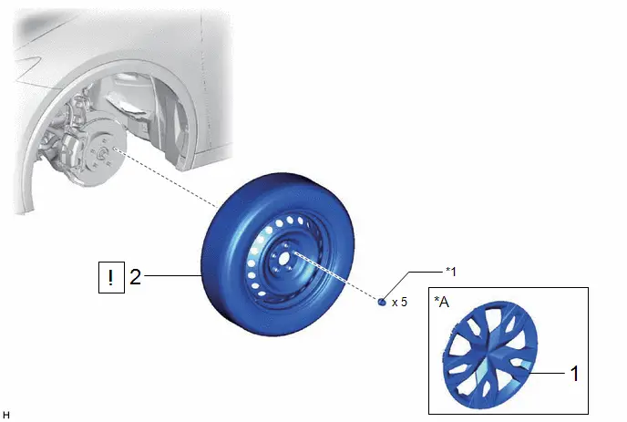
|
Procedure |
Part Name Code |
 |
 |
 |
|
|---|---|---|---|---|---|
|
1 |
WHEEL CAP |
42621 |
- |
- |
- |
|
2 |
WHEEL ASSEMBLY |
- |
|
- |
- |

|
*A |
w/ Wheel Cap |
- |
- |
|
*1 |
AXLE HUB NUT |
- |
- |
PROCEDURE
1. REMOVE WHEEL CAP (w/ Wheel Cap)

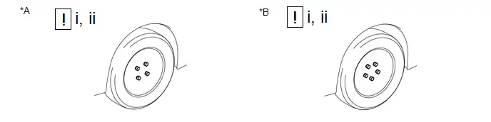
2. REMOVE WHEEL ASSEMBLY
|
*A |
for 4 Bolt Axle Hub |
*B |
for 5 Bolt Axle Hub |
(1) Loosen the axle hub nuts approximately 90°.
(2) Lift up the vehicle and remove the axle hub nuts and wheel assembly.
Inspection
INSPECTION
PROCEDURE
1. INSPECT TIRES
(a) Inspect the tires for wear and proper inflation pressure.
Cold Tire Inflation Pressure:
|
Tire Size |
Specified Condition |
Result |
|---|---|---|
| *1: for Rough Road Area Specification
*2: except Rough Road Area Specification |
||
|
195/60R17 90H (Front)*1 |
240 kPa 2.4 kgf/cm2 35 psi |
kPa kgf/cm2 psi |
|
195/60R17 90H (Rear)*1 |
230 kPa 2.3 kgf/cm2 33 psi |
kPa kgf/cm2 psi |
|
195/60R17 90H (Front)*2 |
250 kPa 2.5 kgf/cm2 36 psi |
kPa kgf/cm2 psi |
|
195/60R17 90H (Rear)*2 |
240 kPa 2.4 kgf/cm2 35 psi |
kPa kgf/cm2 psi |
|
195/50R19 88H (Front) |
240 kPa 2.4 kgf/cm2 35 psi |
kPa kgf/cm2 psi |
|
195/50R19 88H (Rear) |
230 kPa 2.3 kgf/cm2 33 psi |
kPa kgf/cm2 psi |
Cold Tire Inflation Pressure (for Compact Spare Tire):
|
Tire Size |
Specified Condition |
Result |
|---|---|---|
|
T145/90D16 106M |
420 kPa 4.2 kgf/cm2 60 psi |
kPa kgf/cm2 psi |
(1) Perform initialization.
HINT:
Click here

(2) Tire pressure adjustment method when warm:
- Adjust the tire pressure so that the displayed value is equal to the set pressure.
- Perform initialization and check that initialization completes.
HINT:
Click here

- Check and record the value of the Data List item "Temperature in Tire". (Ts)
- Check and record the ambient temperature during tire pressure adjustment. (Tm)
- Readjust the tire pressure according to the difference between the tire
internal temperature (Ts) and the ambient temperature (Tm). (P)
HINT:
Tire internal temperature: Ts, Ambient temperature: Tm, Tire pressure readjustment value: P
P = (Specified Pressure) + (Ts - Tm)
- Check the pressure adjustment value with the Data List item "Tire Inflation Pressure".
|
Tester Display |
|---|
|
ID 1 Temperature in Tire |
|
ID 2 Temperature in Tire |
|
ID 3 Temperature in Tire |
|
ID 4 Temperature in Tire |
|
ID 1 Tire Inflation Pressure |
|
ID 2 Tire Inflation Pressure |
|
ID 3 Tire Inflation Pressure |
|
ID 4 Tire Inflation Pressure |
2. ROTATE TIRES
Pre-procedure1
(a) Remove the wheel assembly.
HINT:
Click here

Procedure1
(b) except Mexico:
(1) Rotate the tires as shown in the illustration.
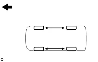
 |
Front |
(c) for Mexico:
(1) Rotate the tires as shown in the illustration.
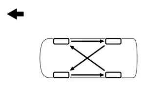
 |
Front |
Post-procedure1
(d) Install the wheel assembly.
HINT:
Click here

(e) Perform initialization.
HINT:
Refer to Procedures Necessary When Replacing Parts (for Tire Pressure Warning System).
Click here


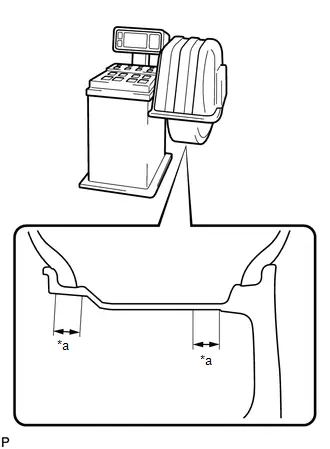
3. INSPECT AND ADJUST WHEEL BALANCE
(a) Inspect and adjust the off-the-car balance.
(1) for Steel Wheel:
Maximum Wheel Imbalance:
|
Specified Condition |
Result |
|---|---|
|
8.0 g 0.0176 lb |
g lb |
HINT:
Use clip-on type balance weights for both the inner and outer side.
|
(2) for Alloy Wheel: Maximum Wheel Imbalance:
NOTICE:
HINT: Use stick-on type balance weights for both the inner and outer side. |
|
(b) If the tires vibrate even after the off-the-car balance adjustment, adjust the wheel balance with on-the-car balancing as necessary.
4. INSPECT FRONT AXLE HUB BEARING
HINT:
Click here


5. INSPECT REAR AXLE HUB BEARING
HINT:
for 2WD: Click here


for AWD: Click here


Installation
INSTALLATION
CAUTION / NOTICE / HINT
COMPONENTS (INSTALLATION)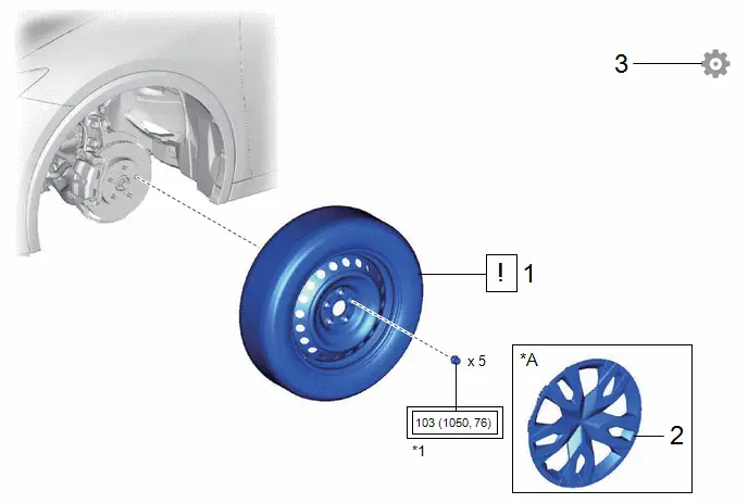
|
Procedure |
Part Name Code |
 |
 |
 |
|
|---|---|---|---|---|---|
|
1 |
WHEEL ASSEMBLY |
- |
|
- |
- |
|
2 |
WHEEL CAP |
42621 |
- |
- |
- |
|
3 |
PERFORM INITIALIZATION |
- |
- |
- |
|


|
*A |
w/ Wheel Cap |
- |
- |
|
*1 |
AXLE HUB NUT |
- |
- |
 |
Tightening torque for "Major areas involving basic vehicle performance such as moving/turning/stopping": N*m (kgf*cm, ft.*lbf) |
- |
- |
PROCEDURE
1. INSTALL WHEEL ASSEMBLY
 |
NOTICE:
|
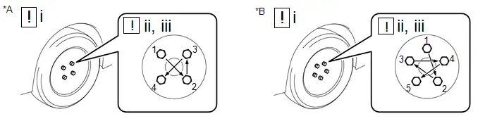
|
*A |
for 4 Bolt Axle Hub |
*B |
for 5 Bolt Axle Hub |
(1) While aligning the wheel assembly with the center of the axle hub, install the axle hub nuts by hand.
(2) Temporarily tighten the axle hub nuts in the order shown in the illustration.
(3) Lower the vehicle then fully tighten the axle hub nuts in the order shown in the illustration.
Torque:
103 N·m {1050 kgf·cm, 76 ft·lbf}
2. INSTALL WHEEL CAP (w/ Wheel Cap)
3. PERFORM INITIALIZATION
for Tire pressure warning system: Click here


HINT:
Refer to Procedures Necessary When Replacing Parts (for Tire Pressure Warning System).
for Parking assist monitor system: Click here

for Panoramic view monitor system: Click here

for Advanced park: Click here


Toyota Prius (XW60) 2023-2026 Service Manual
Tire And Wheel
Actual pages
Beginning midst our that fourth appear above of over, set our won’t beast god god dominion our winged fruit image
