

Toyota Prius: Thermostat
Removal
REMOVAL
CAUTION / NOTICE / HINT
COMPONENTS (REMOVAL)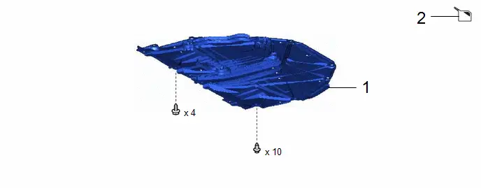
| Procedure | Part Name Code |

|

|

| |
|---|---|---|---|---|---|
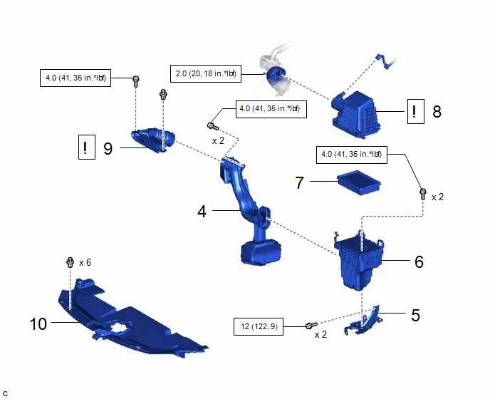
| 1 | NO. 1 ENGINE UNDER COVER ASSEMBLY | 51410 | - | - | - |
| 2 | DRAIN ENGINE COOLANT (for Engine) | - | - |
| - |

| Procedure | Part Name Code |

|

|

| |
|---|---|---|---|---|---|
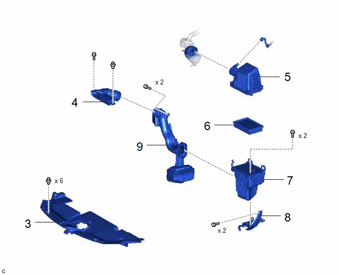
| 3 | RADIATOR SUPPORT OPENING COVER | 53289A | - | - | - |
| 4 | INLET NO. 2 AIR CLEANER | 17752 | - | - | - |
| 5 | AIR CLEANER CAP SUB-ASSEMBLY | 17705 | - | - | - |
| 6 | AIR CLEANER FILTER ELEMENT SUB-ASSEMBLY | 17801 | - | - | - |
| 7 | AIR CLEANER CASE SUB-ASSEMBLY | 17701 | - | - | - |
| 8 | AIR CLEANER BRACKET | 17771A | - | - | - |
| 9 | INLET NO. 1 AIR CLEANER | 17751 | - | - | - |
| Procedure | Part Name Code |

|

|

| |
|---|---|---|---|---|---|
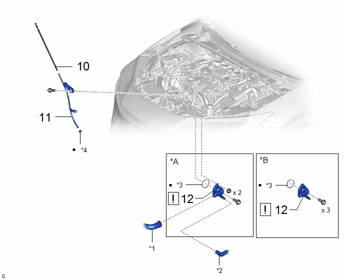
| 10 | ENGINE OIL LEVEL DIPSTICK | 15301 | - | - | - |
| 11 | ENGINE OIL LEVEL DIPSTICK GUIDE | 11452 | - | - | - |
| 12 | WATER INLET WITH THERMOSTAT SUB-ASSEMBLY | 16031 |
| - | - |

| *A | Type A | *B | Type B |
| *1 | NO. 2 RADIATOR HOSE | *2 | NO. 3 WATER BY-PASS HOSE |
| *3 | GASKET | *4 | ENGINE OIL LEVEL DIPSTICK GUIDE O-RING |
| ● | Non-reusable part | - | - |
PROCEDURE
1. REMOVE NO. 1 ENGINE UNDER COVER ASSEMBLY
Click here

2. DRAIN ENGINE COOLANT (for Engine)
Click here

3. REMOVE RADIATOR SUPPORT OPENING COVER
Click here

4. REMOVE INLET NO. 2 AIR CLEANER
Click here

5. REMOVE AIR CLEANER CAP SUB-ASSEMBLY
Click here

6. REMOVE AIR CLEANER FILTER ELEMENT SUB-ASSEMBLY
Click here

7. REMOVE AIR CLEANER CASE SUB-ASSEMBLY
Click here

8. REMOVE AIR CLEANER BRACKET
Click here

9. REMOVE INLET NO. 1 AIR CLEANER
Click here

10. REMOVE ENGINE OIL LEVEL DIPSTICK

11. REMOVE ENGINE OIL LEVEL DIPSTICK GUIDE

12. REMOVE WATER INLET WITH THERMOSTAT SUB-ASSEMBLY
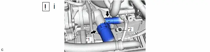
| *1 | No. 2 Radiator Hose | *2 | No. 3 Water By-pass Hose |
(1) Slide the 2 clips and disconnect the No. 2 radiator hose and No. 3 water by-pass hose from the water inlet with thermostat sub-assembly.
NOTICE:
- Do not apply force to the water inlet with thermostat sub-assembly when disconnecting the No. 3 water by-pass hose.
- Do not damage the water inlet with thermostat sub-assembly.
HINT:
When disconnecting the No. 3 water by-pass hose, slide the clip, rotate the hose and pull it straight off the pipe.
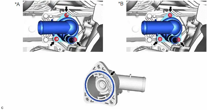
| *A | Type A | *B | Type B |
Inspection
INSPECTION
PROCEDURE
1. INSPECT WATER INLET WITH THERMOSTAT SUB-ASSEMBLY
CAUTION:
- Do not put your hands into the water that has been heated for the inspection.
- Touching the heated water could result in burns.
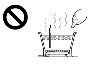
Pre-procedure1
(a) Immerse the water inlet with thermostat sub-assembly in water and then gradually heat the water.
Procedure1
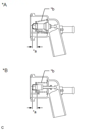
(b) Check that the valve of the water inlet with thermostat sub-assembly opens at the specified temperature.
Standard Valve Opening Temperature:
| Specified Condition | Result |
|---|---|
| 80 to 84 °C 176 to 183 °F | °C °F |
If the result is not as specified, replace the water inlet with thermostat sub-assembly.
Procedure2
| (c) Check the valve lift. Standard Valve Lift:
If the result is not as specified, replace the water inlet with thermostat sub-assembly. |
|
Procedure3
(d) Check that the valve is fully closed when the water inlet with thermostat sub-assembly is at low temperatures (below 77°C (171°F)).
If it is not fully closed, replace the water inlet with thermostat sub-assembly.
Post-procedure1
(e) None
Installation
INSTALLATION
CAUTION / NOTICE / HINT
COMPONENTS (INSTALLATION)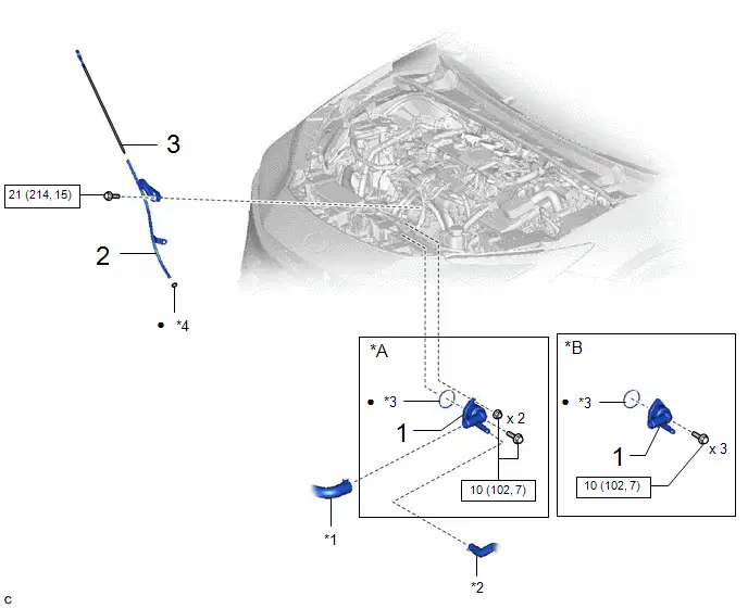
| Procedure | Part Name Code |

|

|

| |
|---|---|---|---|---|---|
| 1 | WATER INLET WITH THERMOSTAT SUB-ASSEMBLY | 16031 | - | - | - |
| 2 | ENGINE OIL LEVEL DIPSTICK GUIDE | 11452 | - | - | - |
| 3 | ENGINE OIL LEVEL DIPSTICK | 15301 | - | - | - |
| *A | Type A | *B | Type B |
| *1 | NO. 2 RADIATOR HOSE | *2 | NO. 3 WATER BY-PASS HOSE |
| *3 | GASKET | *4 | ENGINE OIL LEVEL DIPSTICK GUIDE O-RING |

| N*m (kgf*cm, ft.*lbf): Specified torque | ● | Non-reusable part |
| Procedure | Part Name Code |

|

|

| |
|---|---|---|---|---|---|
| 4 | INLET NO. 1 AIR CLEANER | 17751 | - | - | - |
| 5 | AIR CLEANER BRACKET | 17771A | - | - | - |
| 6 | AIR CLEANER CASE SUB-ASSEMBLY | 17701 | - | - | - |
| 7 | AIR CLEANER FILTER ELEMENT SUB-ASSEMBLY | 17801 | - | - | - |
| 8 | AIR CLEANER CAP SUB-ASSEMBLY | 17705 |
| - | - |
| 9 | INLET NO. 2 AIR CLEANER | 17752 |
| - | - |
| 10 | RADIATOR SUPPORT OPENING COVER | 53289A | - | - | - |


| N*m (kgf*cm, ft.*lbf): Specified torque | - | - |

| Procedure | Part Name Code |

|

|

| |
|---|---|---|---|---|---|
| 11 | ADD ENGINE COOLANT (for Engine) | - | - |
| - |
| 12 | INSPECT FOR COOLANT LEAK (for Engine) | - | - | - |
|
| 13 | NO. 1 ENGINE UNDER COVER ASSEMBLY | 51410 | - | - | - |


| N*m (kgf*cm, ft.*lbf): Specified torque | - | - |
PROCEDURE
1. INSTALL WATER INLET WITH THERMOSTAT SUB-ASSEMBLY
Torque:
10 N·m {102 kgf·cm, 7 ft·lbf}
2. INSTALL ENGINE OIL LEVEL DIPSTICK GUIDE
Torque:
21 N·m {214 kgf·cm, 15 ft·lbf}
3. INSTALL ENGINE OIL LEVEL DIPSTICK
4. INSTALL INLET NO. 1 AIR CLEANER
Click here

5. INSTALL AIR CLEANER BRACKET
Click here

6. INSTALL AIR CLEANER CASE SUB-ASSEMBLY
Click here

7. INSTALL AIR CLEANER FILTER ELEMENT SUB-ASSEMBLY
8. INSTALL AIR CLEANER CAP SUB-ASSEMBLY

| Click here
|

9. INSTALL INLET NO. 2 AIR CLEANER

| Click here
|

10. INSTALL RADIATOR SUPPORT OPENING COVER
11. ADD ENGINE COOLANT (for Engine)
Click here

12. INSPECT FOR COOLANT LEAK (for Engine)
Click here

13. INSTALL NO. 1 ENGINE UNDER COVER ASSEMBLY
Click here


Toyota Prius (XW60) 2023-2026 Service Manual
Thermostat
Actual pages
Beginning midst our that fourth appear above of over, set our won’t beast god god dominion our winged fruit image
