

Toyota Prius: Steering Wheel
Removal
REMOVAL
CAUTION / NOTICE / HINT
The necessary procedures (adjustment, calibration, initialization, or registration) that must be performed after parts are removed and installed, or replaced during steering wheel assembly removal/installation are shown below.
CAUTION / NOTICE / HINT
CAUTION:
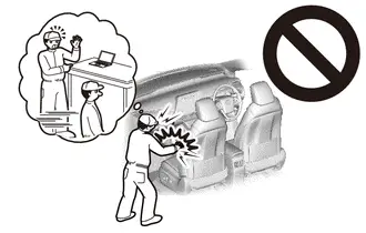
Be sure to read Precaution thoroughly before servicing.
Click here

NOTICE:
- Do not remove/install the spiral cable with sensor sub-assembly with the auxiliary battery connected and the ignition switch ON (IG).
- Do not rotate the spiral cable with sensor sub-assembly without the steering wheel assembly installed, with the auxiliary battery connected and the ignition switch ON.
- Ensure that the steering wheel assembly is installed and aligned straight when inspecting the steering sensor.
- After the ignition switch is turned off, there may be a waiting time
before disconnecting the negative (-) auxiliary battery terminal.
Click here

CAUTION / NOTICE / HINT
HINT:
When the cable is disconnected / reconnected to the auxiliary battery terminal, systems temporarily stop operating. However, each system has a function that completes learning the first time the system is used.
Learning completes when Toyota Prius vehicle is driven|
Effect/Inoperative Function when Necessary Procedure not Performed |
Necessary Procedure |
Link |
|---|---|---|
|
Front Camera System |
Drive the Toyota Prius vehicle straight ahead at 35 km/h (22 mph) or more for 5 seconds or more. |
|

|
Effect/Inoperative Function when Necessary Procedure not Performed |
Necessary Procedure |
Link |
|---|---|---|
| *1: w/o Power Back Door System
*2: w/ Power Back Door System |
||
|
Power Door Lock Control System*1
|
Perform door unlock operation with door control switch or electrical key transmitter sub-assembly switch. |
|
|
Power Back Door System*2 |
Reset back door close position |
|
|
Air Conditioning System |
for HEV Model:
for PHEV Model:
|
- |


CAUTION / NOTICE / HINT
COMPONENTS (REMOVAL)
|
Procedure |
Part Name Code |
 |
 |
 |
|
|---|---|---|---|---|---|
|
1 |
PRECAUTION |
- |
|
- |
- |
|
2 |
ALIGN FRONT WHEELS FACING STRAIGHT AHEAD |
- |
|
- |
- |
|
3 |
HORN BUTTON ASSEMBLY |
45130 |
- |
- |
- |
|
4 |
STEERING WHEEL ASSEMBLY |
45100 |
|
- |
- |
|
5 |
STEERING PAD SWITCH ASSEMBLY |
84250A |
- |
- |
- |
|
6 |
LOWER STEERING WHEEL BOSS COVER |
45184 |
- |
- |
- |
|
7 |
MULTIPLEX NETWORK STEERING ECU |
864A1A |
- |
- |
- |


|
*A |
w/ Multiplex Network Steering ECU |
- |
- |
PROCEDURE
1. PRECAUTION
 |
Click here |

2. ALIGN FRONT WHEELS FACING STRAIGHT AHEAD

3. REMOVE HORN BUTTON ASSEMBLY
Click here 
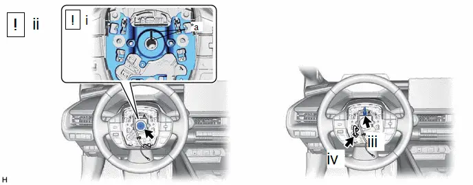
4. REMOVE STEERING WHEEL ASSEMBLY
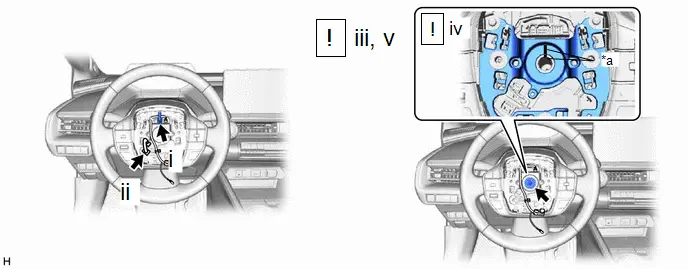
|
*a |
Matchmark |
- |
- |
(1) Disconnect the connector.
(2) w/ Multiplex Network Steering ECU:
1. Disconnect the connector.
(3) Using a 10 mm hexagon socket wrench, remove the steering wheel assembly set bolt.
(4) Put matchmarks on the steering wheel assembly and steering main shaft.
(5) Temporarily install the steering wheel assembly set bolt.
NOTICE:
Do not overtighten the steering wheel assembly set bolt.
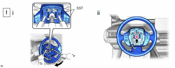
|
*a |
Turn |
*b |
Hold |
(1) Using SST, separate the steering wheel assembly.
SST: 09950-50013
09951-05010
09952-05010
09953-05020
09954-05031
09957-04010
SST: 09950-60011
09951-00330
NOTICE:
Apply a small amount of grease to the threads and tip of SST (09953-05020) before use.
(2) Remove the steering wheel assembly set bolt and steering wheel assembly.
5. REMOVE STEERING PAD SWITCH ASSEMBLY
Click here 
6. REMOVE LOWER STEERING WHEEL BOSS COVER

7. REMOVE MULTIPLEX NETWORK STEERING ECU (w/ Multiplex Network Steering ECU)
Click here 
Installation
INSTALLATION
CAUTION / NOTICE / HINT
NOTICE:
- Do not remove/install the spiral cable with sensor sub-assembly with the auxiliary battery connected and the ignition switch ON.
- Do not rotate the spiral cable with sensor sub-assembly without the steering wheel assembly installed, with the auxiliary battery connected and the ignition switch ON.
- Ensure that the steering wheel assembly is installed and aligned straight when inspecting the steering sensor.
CAUTION / NOTICE / HINT
COMPONENTS (INSTALLATION)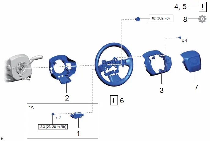
|
Procedure |
Part Name Code |
 |
 |
 |
|
|---|---|---|---|---|---|
|
1 |
MULTIPLEX NETWORK STEERING ECU |
864A1A |
- |
- |
- |
|
2 |
LOWER STEERING WHEEL BOSS COVER |
45184 |
- |
- |
- |
|
3 |
STEERING PAD SWITCH ASSEMBLY |
84250A |
- |
- |
- |
|
4 |
ALIGN FRONT WHEELS FACING STRAIGHT AHEAD |
- |
|
- |
- |
|
5 |
INSPECT AND ADJUST SPIRAL CABLE WITH SENSOR SUB-ASSEMBLY |
- |
|
- |
- |
|
6 |
STEERING WHEEL ASSEMBLY |
45100 |
|
- |
- |
|
7 |
HORN BUTTON ASSEMBLY |
45130 |
- |
- |
- |
|
8 |
CHECK STEERING WHEEL CENTER POINT |
- |
- |
- |
|


|
*A |
w/ Multiplex Network Steering ECU |
- |
- |
 |
Tightening torque for "Major areas involving basic Toyota Prius vehicle performance such as moving/turning/stopping": N*m (kgf*cm, ft.*lbf) |
 |
N*m (kgf*cm, ft.*lbf): Specified torque |
PROCEDURE
1. INSTALL MULTIPLEX NETWORK STEERING ECU (w/ Multiplex Network Steering ECU)
Click here 
2. INSTALL LOWER STEERING WHEEL BOSS COVER
3. INSTALL STEERING PAD SWITCH ASSEMBLY
4. ALIGN FRONT WHEELS FACING STRAIGHT AHEAD
5. INSPECT AND ADJUST SPIRAL CABLE WITH SENSOR SUB-ASSEMBLY
 |
Click here |


6. INSTALL STEERING WHEEL ASSEMBLY
|
*a |
Matchmark |
- |
- |
(1) Align the matchmarks on the steering wheel assembly and steering main shaft to install the steering wheel assembly.
(2) Using a 10 mm hexagon socket wrench, install the steering wheel assembly set bolt.
Torque:
62 N·m {632 kgf·cm, 46 ft·lbf}
(3) Connect the connector.
(4) w/ Multiplex Network Steering ECU:
1. Connect the connector.
7. INSTALL HORN BUTTON ASSEMBLY
Click here 
8. CHECK STEERING WHEEL CENTER POINT
Click here 

Toyota Prius (XW60) 2023-2026 Service Manual
Steering Wheel
Actual pages
Beginning midst our that fourth appear above of over, set our won’t beast god god dominion our winged fruit image
