

Toyota Prius: Steering Knuckle
Removal
REMOVAL
CAUTION / NOTICE / HINT
The necessary procedures (adjustment, calibration, initialization, or registration) that must be performed after parts are removed and installed, or replaced during steering knuckle removal/installation are shown below.
Necessary Procedures After Parts Removed/Installed/Replaced|
Replaced Part or Performed Procedure |
Necessary Procedure |
Effect/Inoperative Function when Necessary Procedure not Performed |
Link |
|---|---|---|---|
| *1: Also necessary after performing a tire rotation.
*2: It is not necessary to perform this procedure if the tire pressure warning valve and transmitters are installed to the same location. *3: The Toyota Prius vehicle height changes because of tire replacement. |
|||
|
Front wheel alignment adjustment |
Perform "Calibration" |
|
|
|
Tires |
|
Tire Pressure Warning System |
Refer to Procedures Necessary When Replacing Parts (for Tire Pressure Warning System) table below
|
|
Rear television camera assembly optical axis (Back camera position setting) |
Parking Assist Monitor System |
|
|
|
Parking assist ECU initialization*3 |
Panoramic View Monitor System |
|
|
|
Advanced Park |
|
||


HINT:
When the cable is disconnected / reconnected to the auxiliary battery terminal, systems temporarily stop operating. However, each system has a function that completes learning the first time the system is used.
Learning completes when Toyota Prius vehicle is driven|
Effect/Inoperative Function when Necessary Procedure not Performed |
Necessary Procedure |
Link |
|---|---|---|
|
Front Camera System |
Drive the Toyota Prius vehicle straight ahead at 35 km/h (22 mph) or more for 5 second or more. |
|

|
Effect/Inoperative Function when Necessary Procedure not Performed |
Necessary Procedure |
Link |
|---|---|---|
| *1: w/o Power Back Door System
*2: w/ Power Back Door System |
||
|
Power Door Lock Control System*1
|
Perform door unlock operation with door control switch or electrical key transmitter sub-assembly switch. |
|
|
Power Back Door System*2 |
Reset back door close position |
|
|
Air Conditioning System |
for HEV Model:
for PHEV Model:
|
- |


NOTICE:
- After the ignition switch is turned off, the radio and display receiver assembly recordsvarious types of memory and settings. As a result, after turning the ignition switch off,make sure to wait at least 3 minutes before disconnecting the cable from the negative(-) auxiliary battery terminal.
- When the cable is disconnected from the negative (-) auxiliary battery terminal and thesecurity lock setting has been enabled, multi-display operations will be disabled uponnext startup unless the password is entered. Be sure to check the security lock settingbefore disconnecting the cable from the negative (-) auxiliary battery terminal.
HINT:
- Use the same procedure for the RH side and LH side.
- The following procedure is for the LH side.
CAUTION / NOTICE / HINT
COMPONENTS (REMOVAL)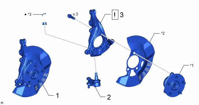
|
Procedure |
Part Name Code |
 |
 |
 |
|
|---|---|---|---|---|---|
|
1 |
FRONT AXLE ASSEMBLY |
- |
- |
- |
- |
|
2 |
FRONT LOWER BALL JOINT ASSEMBLY |
43340A |
- |
- |
- |
|
3 |
STEERING KNUCKLE |
43212 |
|
- |
- |

|
*1 |
FRONT AXLE HUB SUB-ASSEMBLY |
*2 |
FRONT DISC BRAKE DUST COVER |
|
*3 |
COTTER PIN |
- |
- |
|
● |
Non-reusable part |
- |
- |
PROCEDURE
1. REMOVE FRONT AXLE ASSEMBLY
Click here

2. REMOVE FRONT LOWER BALL JOINT ASSEMBLY
 |
Click here
|

3. REMOVE STEERING KNUCKLE
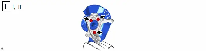
(1) Secure the front axle assembly between aluminum plates in a vise.
NOTICE:
Do not overtighten the vise.
(2) Remove the 3 bolts, front axle hub sub-assembly and front disc brake dust cover from the steering knuckle.
NOTICE:
- Do not drop the front axle hub sub-assembly.
- Be careful not to damage the speed sensor rotor or contact surfaces.
- Do not allow foreign matter to contact the speed sensor rotor or contact surfaces.
Installation
INSTALLATION
CAUTION / NOTICE / HINT
NOTICE:
- After the ignition switch is turned off, the radio and display receiver assembly recordsvarious types of memory and settings. As a result, after turning the ignition switch off,make sure to wait at least 3 minutes before disconnecting the cable from the negative(-) auxiliary battery terminal.
- When the cable is disconnected from the negative (-) auxiliary battery terminal and thesecurity lock setting has been enabled, multi-display operations will be disabled uponnext startup unless the password is entered. Be sure to check the security lock settingbefore disconnecting the cable from the negative (-) auxiliary battery terminal.
HINT:
- Use the same procedure for the RH side and LH side.
- The following procedure is for the LH side.
CAUTION / NOTICE / HINT
COMPONENTS (INSTALLATION)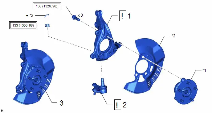
|
Procedure |
Part Name Code |
 |
 |
 |
|
|---|---|---|---|---|---|
|
1 |
STEERING KNUCKLE |
43212 |
|
- |
- |
|
2 |
FRONT LOWER BALL JOINT ASSEMBLY |
43340A |
|
- |
- |
|
3 |
FRONT AXLE ASSEMBLY |
- |
- |
- |
- |


|
*1 |
FRONT AXLE HUB SUB-ASSEMBLY |
*2 |
FRONT DISC BRAKE DUST COVER |
|
*3 |
COTTER PIN |
- |
- |
 |
Tightening torque for "Major areas involving basic Toyota Prius vehicle performance such as moving/turning/stopping": N*m (kgf*cm, ft.*lbf) |
● |
Non-reusable part |
PROCEDURE
1. INSTALL STEERING KNUCKLE
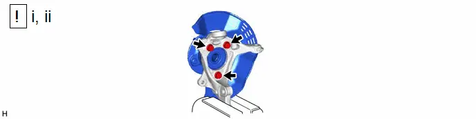
(1) Secure the steering knuckle between aluminum plates in a vise.
NOTICE:
Do not overtighten the vise.
(2) Install the front axle hub sub-assembly and front disc brake dust cover to the steering knuckle with the 3 bolts.
Torque:
130 N·m {1326 kgf·cm, 96 ft·lbf}
NOTICE:
- Be careful not to damage the speed sensor rotor or contact surfaces.
- Do not allow foreign matter to contact the speed sensor rotor or contact surfaces.
2. INSTALL FRONT LOWER BALL JOINT ASSEMBLY
 |
Click here
|

3. INSTALL FRONT AXLE ASSEMBLY
Click here


Toyota Prius (XW60) 2023-2026 Service Manual
Steering Knuckle
Actual pages
Beginning midst our that fourth appear above of over, set our won’t beast god god dominion our winged fruit image
