

Toyota Prius: Smart Key System (for Start Function)
- Precaution
- Parts Location
- System Diagram
- How To Proceed With Troubleshooting
- Customer Problem Analysis Check
- Check For Intermittent Problems
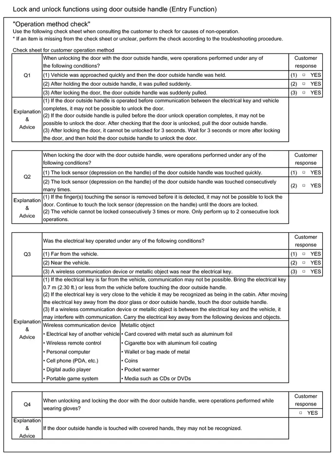
- Operation Check
- Registration
- Customize Parameters
- Problem Symptoms Table
- Terminals Of Ecu
- Data List / Active Test
- Diagnostic Trouble Code Chart
- IG Circuit Short to Ground (B227111)
- ACC Circuit Short to Ground (B227411)
- Starter Circuit Short to Ground (B227511,B227512)
- Engine/Power Switch Signal Compare Failure (B227862)
- Vehicle Speed Signal Circuit Open (B228231,B228262)
- Steering Lock Position Signal Compare Failure (B228562)
- Battery Circuit or Ground Circuit Energization Malfunction (B228B00)
- Wireless Starter Component Internal Failure (B277A96)
- Steering Lock System Component Internal Failure (B278196,B278211,B278215,B279F1C)
- Antenna Coil Circuit Voltage Out of Range (B27841C)
- ID-BOX Component Internal Failure (B278D96)
- Immobiliser Amp Missing Message (B278E87)
- ID-BOX Calibration / Parameter Memory Failure (B279046)
- Engine Immobiliser System Signal (Some Circuit Quantity, Reported via Serial Data) Invalid (B279986)
- Engine Immobiliser System Circuit Short to Battery (B279A12)
- Engine Immobiliser System Incorrect Assembly (B279C95)
- Front Floor Electrical Key Oscillator Circuit Open (B27A513)
- Rear Floor 2 Electrical Key Oscillator Circuit Open (B27A713)
- Brake Switch "A" Signal Compare Failure (P057162)
- Lost Communication with Gear Shift Control Module "A" Missing Message (U010387,...,U113A87)
- Power Source Mode does not Change to ON (IG and ACC)
- Power Source Mode does not Change to ON (IG)
- Power Source Mode does not Change to ON (ACC)
- Power Source Mode does not Change to ON (READY)
- New Key cannot be Registered
- Additional Key cannot be Registered
- New Key Registration Warning Message is not Displayed
- System Malfunction Message is Displayed on the Multi-information Display
- Security Indicator Light Does not Blink
- Immobiliser System does not Operate Properly
Precaution
PRECAUTION
SYSTEM TYPE DETERMINATION
NOTICE:
For this vehicle, there are 2 types of certification ECU (smart key ECU assembly). Judgement can be performed by using the GTS to check if Data List items "Electrical Key 1 Low Battery History" to "Electrical Key 7 Low Battery History" are displayed or not.
(a) Descriptions for this repair manual are listed in the following table.
| Toyota Prius Vehicle Specification | Expression for this Repair Manual |
|---|---|
| Data List items from "Electrical Key 1 Low Battery History" to "Electrical Key 7 Low Battery History" are displayed on the GTS. | Type A |
| Only Data List items from "Electrical Key 1 Low Battery History" to "Electrical Key 4 Low Battery History" are displayed on the GTS. | Type B |
Type A:
Body Electrical > Smart Key > Data List| Tester Display | Measurement Item | Range | Normal Condition | Diagnostic Note |
|---|---|---|---|---|
| Electrical Key 7 Low Battery History | Low battery transmission history (electronic key 7) | OFF or ON | OFF: Transmitter battery not depleted ON: Transmitter battery depleted | - |
| Electrical Key 6 Low Battery History | Low battery transmission history (electronic key 6) | OFF or ON | OFF: Transmitter battery not depleted ON: Transmitter battery depleted | - |
| Electrical Key 5 Low Battery History | Low battery transmission history (electronic key 5) | OFF or ON | OFF: Transmitter battery not depleted ON: Transmitter battery depleted | - |
| Electrical Key 4 Low Battery History | Low battery transmission history (electronic key 4) | OFF or ON | OFF: Transmitter battery not depleted ON: Transmitter battery depleted | - |
| Electrical Key 3 Low Battery History | Low battery transmission history (electronic key 3) | OFF or ON | OFF: Transmitter battery not depleted ON: Transmitter battery depleted | - |
| Electrical Key 2 Low Battery History | Low battery transmission history (electronic key 2) | OFF or ON | OFF: Transmitter battery not depleted ON: Transmitter battery depleted | - |
| Electrical Key 1 Low Battery History | Low battery transmission history (electronic key 1) | OFF or ON | OFF: Transmitter battery not depleted ON: Transmitter battery depleted | - |
Type B:
Body Electrical > Smart Key > Data List| Tester Display | Measurement Item | Range | Normal Condition | Diagnostic Note |
|---|---|---|---|---|
| Electrical Key 4 Low Battery History | Low battery transmission history (electronic key 4) | OFF or ON | OFF: Transmitter battery not depleted ON: Transmitter battery depleted | - |
| Electrical Key 3 Low Battery History | Low battery transmission history (electronic key 3) | OFF or ON | OFF: Transmitter battery not depleted ON: Transmitter battery depleted | - |
| Electrical Key 2 Low Battery History | Low battery transmission history (electronic key 2) | OFF or ON | OFF: Transmitter battery not depleted ON: Transmitter battery depleted | - |
| Electrical Key 1 Low Battery History | Low battery transmission history (electronic key 1) | OFF or ON | OFF: Transmitter battery not depleted ON: Transmitter battery depleted | - |
CAUTION REGARDING INTERFERENCE WITH ELECTRONIC DEVICES
CAUTION:
As weak radio waves are emitted from the electrical key transmitter sub-assembly, if a pacemaker is being used, be sure to read the pacemaker instruction manual and the following.
-
People with implantable cardiac pacemakers, cardiac resynchronization therapy-pacemakers or implantable cardioverter defibrillators should keep away from the smart key system antennas. The radio waves may affect the operation of such devices. If necessary, the entry function can be disabled. Ask your dealer for details, such as the frequency of radio waves and timing of the emitted radio waves. Then, consult your doctor to see if you should disable the start function.
Smart key system antennas: Click here

Remote parking antenna: Click here

- User of any electrical medical device other than implantable cardiac pacemakers, cardiac resynchronization therapy-pacemakers or implantable cardioverter defibrillators should consult the manufacturer of the device for information about its operation under the influence of radio waves. Radio waves could have unexpected effects on the operation of such medical devices.
-
Ask your dealer for details for disabling the smart key system.
Exterior antenna
- Front door outside handle assembly (for Driver Door)
- Front door outside handle assembly (for Front Passenger Door)*1
- Electrical key antenna (outside luggage compartment)*1
- Remote parking antenna assembly*2
Interior antenna
- No. 1 indoor electrical key antenna assembly (front floor)
- No. 2 indoor electrical key antenna assembly (rear floor)
- *1: w/ Front Passenger Door Entry Function
- *2: w/ Advanced Park (Remote Controlled Function)
HINT:
The smart key system can be disabled by a customize setting.
Click here

PRECAUTION FOR DISCONNECTING CABLE FROM NEGATIVE (-) AUXILIARY BATTERY TERMINAL
NOTICE:
-
After the ignition switch is turned off, there may be a waiting time before disconnecting the negative (-) auxiliary battery terminal.
Click here

HINT:
When disconnecting and reconnecting the auxiliary battery, there is an automatic learning function that completes learning when the respective system is used.
Click here


PRECAUTION WHEN USING GTS
(a) When using the GTS with the ignition switch off, perform lock and unlock operations using the door control switch of the multiplex network master switch assembly at intervals of 1.5 seconds or less until communication between the GTS and the Toyota Prius vehicle begins, and then select the vehicle model manually.
Then select Model Code "KEY REGIST" under manual mode and enter the following menus: Body Electrical / Smart Key(CAN). While using the GTS, periodically perform lock and unlock operations using the door control switch of the multiplex network master switch assembly at intervals of 1.5 seconds or less to maintain communication between the GTS and the Toyota Prius vehicle.
PRECAUTION FOR ACC CUSTOMIZE
(a) When performing an inspection, make sure that "ACC Customize" is set to "ON" using the multi-display.
Click here

HINT:
When "ACC Customize" is set to "ON" (ACC supply power enabled), the certification ECU (smart key ECU assembly) controls the ACC relay on and off. When "ACC Customize" is set to "OFF" (ACC supply power disabled), the certification ECU (smart key ECU assembly) and radio and display receiver assembly control the ACC relay on and off.
Therefore, inspection conditions and results may differ depending on whether "ACC customize" is set to ON or OFF when inspecting ACC related terminals or the Data List.
PRECAUTION FOR REGISTRATION
(a) If replacing any of the following parts, refer to Registration.
Click here

(1) Certification ECU (smart key ECU assembly)
(2) Hybrid Toyota Prius vehicle control ECU
(3) Electrical key transmitter sub-assembly
(4) ID code box (immobiliser code ECU)
(5) Main body ECU (multiplex network body ECU)
(6) DCM (telematics transceiver)*
- *: for Remote Connect Compatible Type
Parts Location
PARTS LOCATION
ILLUSTRATION
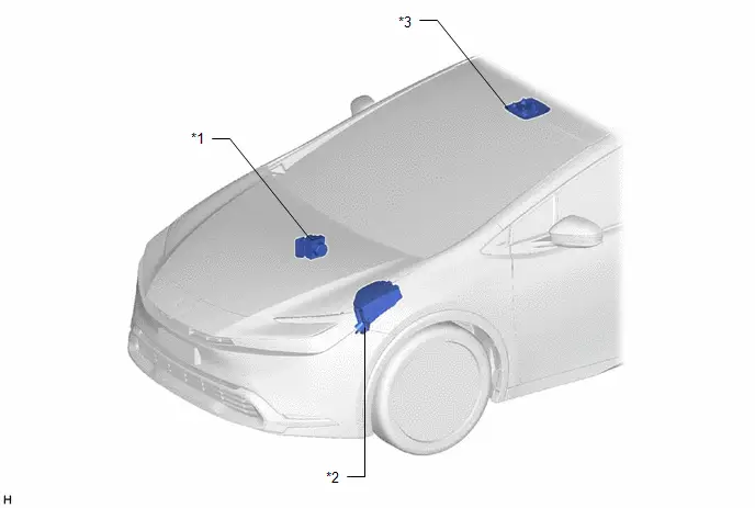
| *1 | BRAKE ACTUATOR ASSEMBLY - NO. 2 SKID CONTROL ECU | *2 | NO. 1 ENGINE ROOM RELAY BLOCK AND NO. 1 JUNCTION BLOCK ASSEMBLY - IGP RELAY |
| *3 | MAP LIGHT ASSEMBLY - SECURITY INDICATOR LIGHT | - | - |
ILLUSTRATION
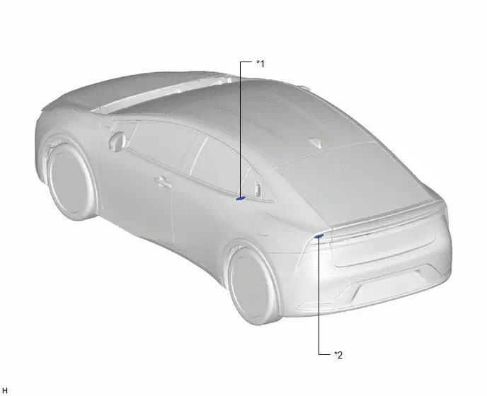
| *1 | NO. 1 INDOOR ELECTRICAL KEY ANTENNA ASSEMBLY (FRONT FLOOR) | *2 | NO. 2 INDOOR ELECTRICAL KEY ANTENNA ASSEMBLY (REAR FLOOR) |
ILLUSTRATION
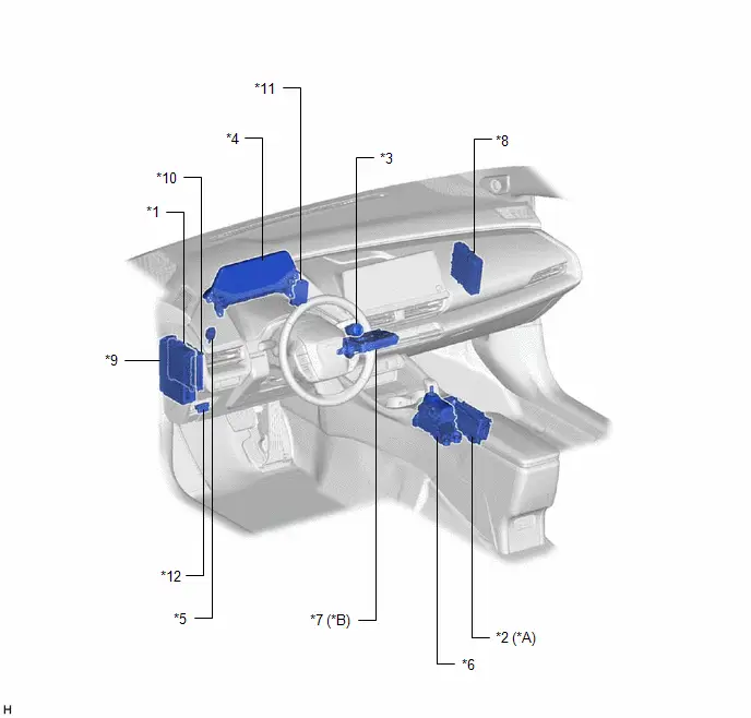
| *A | w/ Wireless Charging System | *B | for Remote Connect Compatible Type |
| *1 | MAIN BODY ECU (MULTIPLEX NETWORK BODY ECU) | *2 | MOBILE WIRELESS CHARGER CRADLE ASSEMBLY |
| *3 | POWER SWITCH | *4 | COMBINATION METER ASSEMBLY |
| *5 | STOP LIGHT SWITCH ASSEMBLY | *6 | TRANSMISSION FLOOR SHIFT ASSEMBLY |
| *7 | DCM (TELEMATICS TRANSCEIVER) | *8 | HYBRID Toyota Prius Vehicle CONTROL ECU |
| *9 | POWER DISTRIBUTION BOX ASSEMBLY - ACC RELAY - IGR NO. 1 RELAY - IGR NO. 2 RELAY - AM2 FUSE - STOP FUSE - ECU-ACC FUSE - ECU-IGR NO. 1 FUSE - ECU-IGR NO. 2 FUSE - BA RELAY - BA NO. 1 FUSE - BA NO. 2 FUSE | *10 | CERTIFICATION ECU (SMART KEY ECU ASSEMBLY) |
| *11 | ID CODE BOX (IMMOBILISER CODE ECU) | *12 | DLC3 |
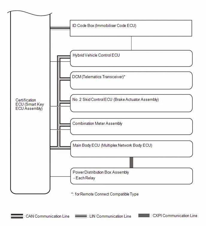
System Diagram
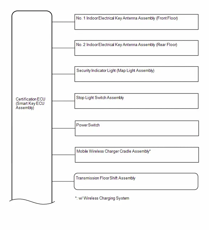
SYSTEM DIAGRAM
SMART KEY SYSTEM (for Start Function)
SMART KEY SYSTEM (for Entry Function)
Click here

How To Proceed With Troubleshooting
CAUTION / NOTICE / HINT
NOTICE:
- Do not perform "Smart Code Reset" (all key ID erasure) until all malfunctions and symptoms have been confirmed and resolved. If all key ID erasure is performed without confirming or resolving malfunctions, key registration will be unable to be performed, resulting in unnecessary part replacement.
- Make sure that the smart key system has not been disabled by a customize setting.
HINT:
- Replace parts related to the wireless door lock control system and smart key system according to the inspection procedure.
- If the wireless door lock control system and smart key system do not operate, check the customize settings and make sure that the wireless door lock control system and smart key system are not disabled.
-
The wireless door lock control system and smart key system primarily use the following systems.
- Power door lock system
- Wireless door lock control system
- Smart key system (for Entry Function)
-
Smart key system (for Start Function)
- Immobiliser function
- If 2 or more electrical key transmitter sub-assemblies are registered to the system, make sure to perform troubleshooting with all of them.
PROCEDURE
| 1. | Toyota Prius Vehicle BROUGHT TO WORKSHOP |
(a) Confirm how the vehicle was brought to the workshop.
- Vehicle was driven.
- Vehicle was towed.
HINT:
The cause of the malfunction may be narrowed down by confirming whether the vehicle was driven or towed.
|

| 2. | CUSTOMER PROBLEM ANALYSIS |
HINT:
- In troubleshooting, confirm that the problem symptoms have been accurately identified. Preconceptions should be discarded in order to make an accurate judgment. To clearly understand what the problem symptoms are, it is extremely important to ask the customer about the problem and the conditions at the time the malfunction occurred.
- Gather as much information as possible for reference. Past malfunctions that seem unrelated may also help in some cases.
-
The following 5 items are important points for problem analysis:
What
Toyota Prius Vehicle model, system name
When
Date and time, frequency, whether the problem occurred recently or has been occurring for a long time
Where
Whether the problem occurs at specified location
Under what conditions?
Whether the doors were locked or unlocked, whether the ignition switch was ON, whether the hybrid control system was starting
How did it happen?
Ask the customer for details about the Toyota Prius vehicle operating conditions, environment and malfunction.

|

| 3. | BASIC CHECK |
(a) Measure the auxiliary battery voltage with the ignition switch off.
Standard Voltage:
11 to 14 V
HINT:
- A simple method to determine whether the auxiliary battery is depleted is to operate the horn.
- If the auxiliary battery voltage is below 11 V, recharge or replace the auxiliary battery.
(b) Check for blown fuses, open or shorted wire harnesses, improperly connected connectors and other problems in areas that can be visually inspected.
(c) Check the connection of each connector and check them for deformation or damage.
|

| 4. | CHECK DTCS AND SAVE OPERATION HISTORY |
(a) Using the GTS, enter the following menus: System Select / Health Check
HINT:
- If DTCs are output, perform troubleshooting for the DTCs.
- Save all output DTCs and operation history.
-
Operation history can also be checked using the Utility menu of the GTS.
Click here

| Result | Proceed to |
|---|---|
| No DTCs are output | A |
| Wireless door lock system and smart key system DTCs are output | B |
| DTCs other than wireless door lock system and smart key system DTCs are output | C |
| B |

| GO TO DIAGNOSTIC TROUBLE CODE CHART |
| C |

| GO TO DIAGNOSTIC TROUBLE CODE CHART |
|

| 5. | CHECK PROBLEM SYMPTOMS |
(a) Based on the customer problem analysis, check the problem symptoms.
Click here

| Result | Proceed to |
|---|---|
| The problem symptom can be confirmed | A |
| The problem symptom cannot be confirmed | B |
| B |

| GO TO CHECK FOR INTERMITTENT PROBLEMS |
|

| 6. | CHECK CUSTOMIZE ITEMS |
(a) Use the following customize setting methods to confirm that the smart key system is enabled.
- Using the GTS
- Using the multi-display
- Using manual operation
Check the customize settings.
Click here

(b) Use the following customize setting methods to confirm that the wireless door lock system is enabled.
- Using the GTS
- Using the multi-display
Check the customize settings.
Click here

HINT:
- Even when the smart key system is disabled by a customize setting, the hybrid control system can be started by an emergency key operation.
- If the smart key system or wireless door lock control system is disabled, all entry and start functions or wireless functions will not operate.
| Result | Proceed to |
|---|---|
| Wireless door lock control system and smart key system are enabled | A |
| Smart key system is disabled | B |
| Wireless door lock system is disabled | C |
| B |

| GO TO CUSTOMIZE PARAMETERS |
| C |

| GO TO CUSTOMIZE PARAMETERS |
|

| 7. | CHECK POWER DOOR LOCK SYSTEM |
(a) Check the power door lock system.
Click here

| Result | Proceed to |
|---|---|
| Power door lock system operates properly | A |
| Power door lock system does not operate properly | B |
| B |

| GO TO POWER DOOR LOCK SYSTEM (HOW TO PROCEED WITH TROUBLESHOOTING)
|


|

| 8. | CHECK WIRELESS DOOR LOCK CONTROL SYSTEM |
(a) Check the wireless door lock control system.
Click here

| Result | Proceed to |
|---|---|
| All functions operate properly | A |
| Wireless lock/unlock functions do not operate (entry and start functions also do not operate) | B |
| Wireless lock/unlock functions do not operate (entry and start functions operate) | C |
| Door ajar warning does not operate | D |
| Answer-back (buzzer sounds and hazard lights flash) function does not operate | E |
| B |

| GO TO SMART KEY SYSTEM (for Entry Function) (All Door Entry Lock/Unlock Functions and Wireless Functions do not Operate) |
| C |

| REPLACE ELECTRICAL KEY TRANSMITTER SUB-ASSEMBLY |
| D |

| GO TO LIGHTING SYSTEM (Door Courtesy Switch Circuit)
|


| E |

| GO TO WIRELESS DOOR LOCK CONTROL SYSTEM (No Answer-Back) |
|

| 9. | CHECK SMART KEY SYSTEM (for Entry Function) |
(a) Check the smart key system (for Entry Function).
Click here

| Result | Proceed to |
|---|---|
| All functions operate properly | A |
| Entry lock/unlock functions do not operate for all doors (wireless function also does not operate) | B |
| Entry lock/unlock functions do not operate for all doors (wireless function operates) | C |
| Entry lock/unlock functions do not operate only for driver side door | D |
| Entry lock/unlock functions do not operate only for front passenger side door | E |
| Entry lock/unlock functions do not operate only for back door | F |
| Entry lock function does not operate only for driver side door (unlock function operates) | G |
| Entry lock function does not operate only for passenger side door (unlock function operates) | H |
| Entry lock function does not operate only for back door (unlock function operates) | I |
| Entry unlock function does not operate only for driver side door (lock function operates) | J |
| Entry unlock function does not operate only for passenger side door (lock function operates) | K |
| Entry unlock function does not operate only from back door (lock function operates) | L |
| Smart key system exterior warning and answer-back buzzer do not sound | M |
| Smart key system interior warning does not sound | N |
| Touching unlock sensor for certain period of time does not unlock all doors | O |
| Entry lock function does not operate using close and lock Function* | P |
- *: w/ Power Back Door System
| B |

| GO TO SMART KEY SYSTEM (for Entry Function) (All Door Entry Lock/Unlock Functions and Wireless Functions do not Operate) |
| C |

| GO TO SMART KEY SYSTEM (for Entry Function) (All Door Entry Lock/Unlock Functions do not Operate, but Wireless Functions Operate) |
| D |

| GO TO SMART KEY SYSTEM (for Entry Function) (Driver Side Door Entry Lock and Unlock Functions do not Operate) |
| E |

| GO TO SMART KEY SYSTEM (for Entry Function) (Front Passenger Side Door Entry Lock and Unlock Functions do not Operate) |
| F |

| GO TO SMART KEY SYSTEM (for Entry Function) (Back Door Entry Lock and Unlock Functions do not Operate) |
| G |

| GO TO SMART KEY SYSTEM (for Entry Function) (Driver Side Door Entry Lock Function does not Operate) |
| H |

| GO TO SMART KEY SYSTEM (for Entry Function) (Front Passenger Side Door Entry Lock Function does not Operate) |
| I |

| GO TO SMART KEY SYSTEM (for Entry Function) (Back Door Entry Lock Function does not Operate) |
| J |

| GO TO SMART KEY SYSTEM (for Entry Function) (Driver Side Door Entry Unlock Function does not Operate) |
| K |

| GO TO SMART KEY SYSTEM (for Entry Function) (Front Passenger Side Door Entry Unlock Function does not Operate) |
| L |

| GO TO SMART KEY SYSTEM (for Entry Function) (Back Door Entry Unlock Function does not Operate) |
| M |

| GO TO SMART KEY SYSTEM (for Entry Function) (Entry Exterior Alarm and Answer-back Buzzer do not Sound) |
| N |

| GO TO SMART KEY SYSTEM (for Entry Function) (Entry Interior Alarm does not Sound)
|


| O |

| GO TO SMART KEY SYSTEM (for Entry Function) (Touching Unlock Sensor for Certain Period of Time does not Unlock All Doors) |
| P |

| GO TO SMART KEY SYSTEM (for Entry Function) (Entry Lock Function does not Operate Using Close & Lock Function) |
|

| 10. | CHECK SMART KEY SYSTEM (for Start Function) |
(a) Check the smart key system (for Start Function).
Click here

| Result | Proceed to |
|---|---|
| All functions operate properly | A |
| Power source mode changing function does not operate correctly (power source mode cannot be changed to ACC, but can be changed to ON) | B |
| Only BA power source mode does not operate correctly | C |
| Security indicator light does not blink | D |
| System malfunction message is displayed on the multi-information display | E |
| Result | Proceed to |
|---|---|
| Push-button start function does not operate | F |
| Immobiliser function does not operate | G |
| Power source mode changing function does not operate (power source mode cannot be changed to ACC or ON) | H |
| Power source mode changing function does not operate correctly (power source mode can be changed to on ACC, but not ON) | I |
| Immobiliser function does not operate (security indicator light does not turn off) | J |
| B |

| GO TO SMART KEY SYSTEM (for Start Function) (Power Source Mode does not Change to ON (ACC)) |
| C |

| GO TO PROBLEM SYMPTOMS TABLE (Only BA Power Source Mode Changing Function does not Operate correctly .) |
| D |

| GO TO SMART KEY SYSTEM (for Start Function) (Security Indicator Light Does not Blink) |
| E |

| GO TO SMART KEY SYSTEM (for Start Function) (System Malfunction Message is Displayed on the Multi-information Display) |
| F |

| GO TO SMART KEY SYSTEM (for Start Function) (Power Source Mode does not Change to ON (READY)) |
| G |

| GO TO SMART KEY SYSTEM (for Start Function) (Immobiliser System does not Operate Properly) |
| H |

| GO TO SMART KEY SYSTEM (for Start Function) (Power Source Mode does not Change to ON (IG and ACC)) |
| I |

| GO TO SMART KEY SYSTEM (for Start Function) (Power Source Mode does not Change to ON (IG)) |
| J |

| GO TO SMART KEY SYSTEM (for Start Function) (Immobiliser System does not Operate Properly) |
|

| 11. | CHECK ELECTRICAL KEY REGISTRATION FUNCTION |
(a) Check the electrical key registration function.
Click here

| Result | Proceed to |
|---|---|
| Electrical key registration function operates properly | A |
| Cannot register new keys | B |
| Cannot register additional keys | C |
| Additional key registration display is not displayed | D |
| A |

| USE SIMULATION METHOD TO CHECK |
| B |

| GO TO SMART KEY SYSTEM (for Start Function) (New Key cannot be Registered) |
| C |

| GO TO SMART KEY SYSTEM (for Start Function) (Additional Key cannot be Registered) |
| D |

| GO TO SMART KEY SYSTEM (for Start Function) (New Key Registration Warning Message is not Displayed) |
Customer Problem Analysis Check
CUSTOMER PROBLEM ANALYSIS CHECK
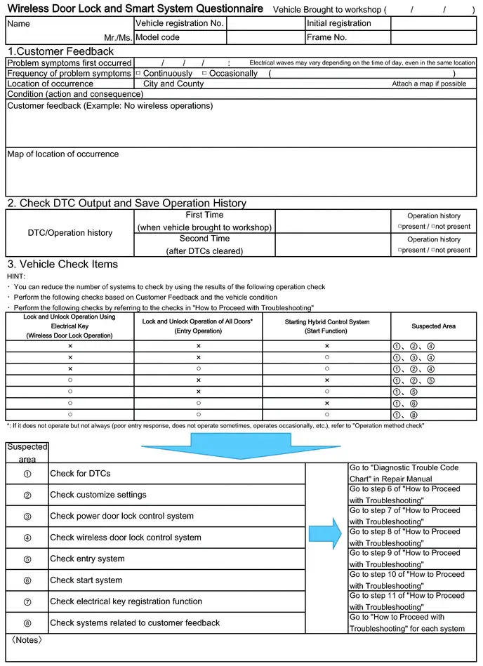
HINT:
Be sure to ask the customer in detail about the following points concerning the vehicle operating conditions, environment and problem, and then check for DTCs.
- If the entry unlock function does not operate.
- If the power source mode does not change even though the power switch was pressed (does not change to ACC).
- If the entry lock function does not operate.
- If the entry lock/unlock function does not operate for all doors.
- If both the entry lock and unlock functions do not operate.
- If the wireless lock and unlock functions do not operate.
- If the hybrid control system cannot be started the push-button start function.
- If a hybrid control system start was attempted by holding the electrical key transmitter sub-assembly near the power switch and then pressing the power switch.
- If the warning buzzers inside the Toyota Prius vehicle do not sound.
- If the warning buzzers outside the vehicle do not sound.
If it is suspected that wave interference is likely, be sure to ask the customer in detail about the following points concerning the vehicle operating conditions, environment and problem.
- Specific locations where the system does not operate (such as near TV towers, large video displays, wireless garage door opener systems, wireless security cameras, home security systems, etc.).
- Specific times when the system does not operate.
- If the symptoms occurred immediately after purchase or only recently.
- If the system does not operate only when near specific Toyota Prius vehicles (there may be wave interference from the wireless systems of other vehicles).
- If the system operates intermittently.
- If the electrical key transmitter sub-assembly is bundled together with other items.
- If the electrical key transmitter sub-assembly is carried together with other electronic devices, such as cell phones, personal computers, portable music players, other electrical key transmitter sub-assemblies, etc. (make sure to keep the electrical key transmitter sub-assembly at least 0.1 m (0.328 ft.) away from such items).
- Where the electrical key transmitter sub-assembly is being kept when not in use: If the electrical key transmitter sub-assembly is being placed within 1 m (3.28 ft.) of items such as TVs, DVD recorders, induction cookers, rice cookers, dishwashers, modems, cell phones, personal computers, microwave ovens, desk or floor lamps, cordless telephones, etc.
- If there are electronic devices that transmit radio waves placed in the Toyota Prius vehicle.
-
When the transmitter battery was last replaced. The transmitter battery capacity can be approximated using the Key Low Battery Data List item.
Click here

- If the customer installed any optional components (theft deterrent devices, wireless fog lights, etc.) to the Toyota Prius vehicle.
Check For Intermittent Problems
CHECK FOR INTERMITTENT PROBLEMS
NOTICE:
- Operation history is stored in the RAM or EEPROM of the certification ECU (smart key ECU assembly). As the cause of a malfunction stored in the RAM will be cleared when the cable is disconnected from the negative (-) auxiliary battery terminal, do not disconnect the cable from the negative (-) auxiliary battery terminal before checking and recording are complete.
- If the Toyota Prius vehicle or vehicle controls are operated (for example, during initial inspection when the vehicle is brought in for repair) before operation history has been read and saved, the operation history information could be lost.
- The operation history function uses the current system time of the GTS and the time counter inside the controlling ECU to calculate the time shown in the operation history. For this reason, before reading the operation history, first make sure that the GTS system clock is accurately set to the current time.
Toyota Prius Vehicle CONTROL HISTORY (ROB)
HINT:
The certification ECU (smart key ECU assembly) stores the vehicle control history (RoB) of the smart key system and it can be read using the GTS.
(a) Read the Vehicle Control History (RoB) according to the display on the GTS.
Body Electrical > Smart Key > Utility| Tester Display |
|---|
| Toyota Prius Vehicle Control History (RoB) |
| Code | Item List | Item Description | Note |
|---|---|---|---|
| X0A10 | Auto Entry Mode Switch History | The certification ECU mode changed when the GTS was connected. | - |
| X0A11 | Customize (Auto Entry Cancel) | The smart functionality was canceled via customization. | - |
| X0A12 | Engine Start (Inactive) | Hybrid control system could not be started because steering lock status was unlock not confirmed. | - |
| X0A13 | Engine Start | Hybrid control system could not be started because immobiliser was set. | - |
| X0A14 | Radio Wave Interference (RF Reception Not Available) | An attempt was made to start the hybrid control system without a key. | - |
| X0A15 | Engine Start Inactive (Steering Lock System) | Hybrid control system could not be started because steering lock lever was engaged. | - |
| X0A18 | Auto Entry Wireless Operation History (Lock/Unlock) | Lock/unlock was performed by wireless operation. | - |
| X0A19 | Auto Entry Wireless Operation History (Open/Close) | Power slide door/back door was opened/closed by wireless operation. | - |
| X0A1A | Warning Operation History | Warning operation was performed by a function of the certification ECU. | - |
| X0A1B | Registration Function (Reason for Non-operation) | The reason that key registration failed. | - |
| X0A1C | Radio Wave Interference (RF Signal Received) | Smart system did not operate due to effects of radio frequency interference. | - |
| X0A1D | Auto Entry Lock (Inactive) | The reason that entry lock did not operate. | - |
| X0A1E | Auto Entry Unlock (Inactive) | The reason that operations other than entry lock operation did not operate correctly. | - |
HINT:
Some items may not be displayed depending on the specifications of the Toyota Prius vehicle.
(b) Read the Vehicle Control History (RoB) according to the display on the GTS.
Body Electrical > Power Source Control > Utility| Tester Display |
|---|
| Vehicle Control History (RoB) |
| Code | Item List | Item Description | Note |
|---|---|---|---|
| X0A00 | Cause Details of Engine Start / READY ON Failure | The reason that hybrid control system did not start or system did not enter READY ON. | - |
| X0A01 | Cause Details of Engine Stop / READY OFF in IG ON | The reason that hybrid control system stalled or hybrid control system stopped. | - |
| X0A02 | Cause Details of Leave ACC ON / IG ON | The reason that Toyota Prius vehicle power source turned off automatically. | - |
HINT:
Some items may not be displayed depending on the specifications of the vehicle.
SYMPTOM SIMULATION
Click here

Operation Check
OPERATION CHECK
CHECK CUSTOMIZE PARAMETERS
(a) The operation check below is based on the non-customized initial condition of the vehicle. (However, make sure that "ACC Customize" is set to "ON" using the multi-display.)
Click here

CHECK PUSH-BUTTON START FUNCTION
(a) Check the push-button start function:
(1) Get into the Toyota Prius vehicle while carrying the electrical key transmitter sub-assembly with the ignition switch off. With the shift position in P, check that the key indicator display is displayed when the brake pedal is depressed. Check that the hybrid control system starts when the power switch is pressed after the key indicator display is displayed on the multi-information display.
(2) While carrying the electrical key transmitter sub-assembly, check that the power source mode changes in the following order when the power switch is pressed with the brake pedal released: off → ACC* → ON → off.
- *: When "ACC Customize" is set to "ON" using the multi-display
HINT:
If the power switch is pressed with the ignition switch ON and the shift position not in P, the power source mode will change to off, and shift position will change to P.
(3) Check the push-button start function operation range for the front side. Place the electrical key transmitter sub-assembly at either inspection point so that it is facing the direction shown in the illustration, and then check that the hybrid control system can be started.
NOTICE:
Even if the electrical key transmitter sub-assembly is in a Toyota Prius vehicle interior detection area, it may not be properly detected if it is on the instrument panel, in the glove box or on the floor.
HINT:
-
Communication may not be possible if the electrical key transmitter sub-assembly is within 0.2 m (0.656 ft.) of the No. 1 indoor electrical key antenna assembly (front floor).
Click here

- Perform this inspection for both inspection points.
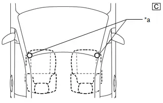
| *a | Electrical Key Transmitter Sub-assembly Inspection Point |
The illustrations shown are examples only.
(4) Check the push-button start function operation range for the luggage compartment. Place the electrical key transmitter sub-assembly at either inspection point so that it is facing the direction shown in the illustration, and then check that the hybrid control system can be started.
NOTICE:
Even if the electrical key transmitter sub-assembly is in a Toyota Prius vehicle interior detection area, it may not be properly detected if it is on the instrument panel, in the glove box or on the floor.
HINT:
-
Communication may not be possible if the electrical key transmitter sub-assembly is within 0.2 m (0.656 ft.) of the center of the No. 2 indoor electrical key antenna assembly (rear floor).
Click here

- Perform this inspection for both inspection points.
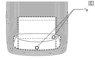
| *a | Electrical Key Transmitter Sub-assembly Inspection Point |
The illustrations shown are examples only.
CHECK POWER SOURCE MODE CHANGING FUNCTION
NOTICE:
-
When "ACC customize" is set to "OFF" using the multi-display, ACC supply power can be disabled.
Click here

- When "ACC Customize" is set to "OFF" using the multi-display, make sure to return the setting to its original state after completing the inspection.
(a) Check the power switch. (ACC customize "ON")
(1) Check that the power source mode changes according to the chart below.
| Shift Position | Brake Pedal | Power Source Mode when Power Switch Pressed |
|---|---|---|
| P | Released | Off → ACC → ON → off |
| P | Released | ON (READY) → off |
| P | Depressed | Off → ON (READY) |
| P | Depressed | ACC → ON (READY) |
| P | Depressed | ON → ON (READY) |
| P | Depressed | ON (READY) → off |
| Not P | Released | ON → off |
| Not P | Released | ON (READY) → off |
| Not P | Depressed | ON → off |
| Not P | Depressed | ON (READY) → off |
(b) Check the power switch. (ACC customize "OFF")
(1) Check that the power source mode changes according to the chart below.
| Shift Position | Brake Pedal | Power Source Mode when Power Switch Pressed |
|---|---|---|
| P | Released | Off → ON → off |
| P | Released | ON (READY) → off |
| P | Depressed | Off → ON (READY) |
| P | Depressed | ON → ON (READY) |
| P | Depressed | ON (READY) → off |
| Not P | Released | ON → off |
| Not P | Released | ON (READY) → off |
| Not P | Depressed | ON → off |
| Not P | Depressed | ON (READY) → off |
CHECK BA POWER SOURCE MODE CHANGING FUNCTION
(a) Check the BA power source:
(1) With all of the doors closed, lock the doors using the entry lock function or wireless function.
(2) After 3 minutes or more have elapsed, unlock the doors using the entry lock function or wireless function.
(3) Open the driver door, enter the Toyota Prius vehicle and close the driver door.
(4) Check that the multi-information display in the combination meter assembly starts up.
(5) Operate the multimedia switch and check that the multi display starts.
CHECK TRANSMITTER BATTERY SAVING MODE FUNCTION
(a) Check the transmitter battery saving mode function:
(1) Press the unlock switch of the electrical key transmitter sub-assembly twice while pressing the lock switch and check that the electrical key transmitter sub-assembly LED blinks 4 times and enters transmitter battery saving mode.
(2) Check that the smart key system does not operate while in transmitter battery saving mode.
HINT:
To cancel transmitter battery saving mode, press a switch of the electrical key transmitter sub-assembly.
CHECK ENTRY CANCEL FUNCTION
(a) Disable the smart key system and check that all functions of the smart key system no longer operate.
Click here

HINT:
When the smart key system is disabled, it is possible to lock and unlock the doors with the wireless function, and the hybrid control system can be started by holding the electrical key transmitter sub-assembly near the power switch.
CHECK KEY DIAGNOSTIC MODE
Click here

Registration
REGISTRATION
PROCEDURE
1. REPAIR INSTRUCTION
CAUTION:
As weak radio waves are emitted from the electrical key transmitter sub-assembly, if a pacemaker is being used, be sure to read the pacemaker instruction manual and the following.
-
People with implantable cardiac pacemakers, cardiac resynchronization therapy-pacemakers or implantable cardioverter defibrillators should keep away from the smart key system antennas. The radio waves may affect the operation of such devices. If necessary, the entry function can be disabled. Ask your dealer for details, such as the frequency of radio waves and timing of the emitted radio waves. Then, consult your doctor to see if you should disable the entry function.
Click here

- User of any electrical medical device other than implantable cardiac pacemakers, cardiac resynchronization therapy-pacemakers or implantable cardioverter defibrillators should consult the manufacturer of the device for information about its operation under the influence of radio waves. Radio waves could have unexpected effects on the operation of such medical devices.
-
Ask your dealer for details for disabling the entry function.
Click here

NOTICE:
PRECAUTION WHEN REPLACING PARTS
-
Code registration is necessary when any of the following parts is replaced with a new one. After replacing a part, any part that has performed registration cannot be returned.
- Certification ECU (smart key ECU assembly)
- ID code box (immobiliser code ECU)
- Electrical key transmitter sub-assembly
- Main body ECU (multiplex network body ECU)
- DCM (telematics transceiver)*1
- Digital key ECU assembly*2
- BLE door digital key receiver assembly*2
- BLE luggage digital key receiver assembly*2
-
BLE indoor digital key receiver assembly*2
- *1: for Remote Connect Compatible Type
- *2: w/ Digital Key System
- Make sure to make a note of the ACC customize setting before replacing the certification ECU (smart key ECU assembly) as ACC customize defaults to ON after replacing the certification ECU (smart key ECU assembly). Then make sure to return the setting to the noted value after replacement.
PRECAUTION FOR REGISTRATION
- Make sure that only 1 electrical key transmitter sub-assembly is in the cabin during registration procedures. If 2 or more electrical key transmitter sub-assemblies are in the cabin simultaneously, the electric waves will interfere with each other, preventing normal registration.
- A maximum of 7 electrical key transmitter sub-assemblies can be registered (this includes any electrical key transmitter sub-assemblies registered when the Toyota Prius vehicle was purchased).
- If the battery is depleted during the electrical key transmitter sub-assembly registration procedure, there may be cases in which the electrical key transmitter sub-assembly cannot be registered again. Therefore, make sure to perform work with a sufficiently charged battery.
- If any of the work times are exceeded, finish the procedure.
- Do not disconnect the battery during the Registration.
- Do not perform operations that create an electrical load such as operating the power windows.
-
If Smart Key System is canceled, registration cannot be performed.
Click here

-
If the digital key system is canceled, registration cannot be performed.
Click here

2. EXPLANATION OF IMMOBILISER KEY ID REGISTRATION PROCEDURE
(a) Addressing customer requests (perform work in chart below in order starting from left)
NOTICE:
If All keys ID erasure (Smart code reset) is performed, the code between the certification ECU (smart key ECU assembly) and the digital key ECU assembly is cleared and the digital key system will not function.
| Customer Request/Condition | Undesignated key permanent erasure | All keys ID erasure (Smart code reset) | New key ID registration | Additional key ID registration | Digital key (owner key) registration |
|---|---|---|---|---|---|
| Refer to PROCEDURE | "5" | "6" | "3" | "4" | * |
| All electrical key transmitter sub-assemblies are lost | - |

|

| - |

|
| Registering additional electrical key transmitter sub-assembly | - | - | - |

| - |
| Making a lost electrical key transmitter sub-assembly unusable |

| - | - | - | - |
- *: Refer to the digital key application procedure then perform the registration procedure.
(b) Addressing customer requests (perform work in chart below in order starting from left) (w/ Digital Key System)
| Customer Request | Condition | All digital keys clearance | Digital key (owner key) registration | All digital keys (share key) clearance |
|---|---|---|---|---|
| Refer to PROCEDURE | "12" | * | "13" | |
| Registering digital key (owner key) | Digital key registered | - |

| - |
| Digital key not registered | - |

| - | |
| Digital key (owner key) lost |

|

| - | |
| Clear all digital keys (share key) | - | - |

| |
- *: Refer to the digital key application procedure then perform the registration procedure.
(c) Addressing malfunctions 1 (perform work in chart below in order starting from left)
Certification ECU (smart key ECU assembly) malfunction| Condition (The number of the electrical key transmitter sub-assemblies customer has brought) | Undesignated key permanent erasure | Replace certification ECU (smart key ECU assembly) | Replace ID code box (immobiliser code ECU) | Replace digital key ECU assembly*1 | - |
|---|---|---|---|---|---|
| Refer to PROCEDURE | "5" | HINT:
| HINT:
| HINT:
| - |
| All electrical key transmitter sub-assemblies | - |

| - | - | Continue to the table below |
| At least 1 electrical key transmitter sub-assembly (Key ID codes can be registered and cleared) |

|

| - | - | Continue to the table below |
| At least 1 electrical key transmitter sub-assembly (Key ID codes cannot be either registered or cleared) | - |

|

|

| Continue to the table below |
| All electrical key transmitter sub-assemblies are lost | - |

|

|

| Continue to the table below |


| Condition (The number of the electrical key transmitter sub-assemblies customer has brought) | New key ID registration | ECU communication ID registration | Remote engine start and stop registration*2 | VIN / digital key ECU serial number registration*1 | Digital key (owner key) registration using the digital key application*1 |
|---|---|---|---|---|---|
| Refer to PROCEDURE | "3" | "8" | "10" | "11" | *3 |
| All electrical key transmitter sub-assemblies |

| - |

| - | - |
| At least 1 electrical key transmitter sub-assembly (Key ID codes can be registered and cleared) |

| - |

| - | - |
| At least 1 electrical key transmitter sub-assembly (Key ID codes cannot be either registered or cleared) |

|

|

|

|

|
| All electrical key transmitter sub-assemblies are lost |

|

|

|

|

|
- *1: w/ Digital Key System
- *2: for Remote Connect Compatible Type
- *3: Refer to the digital key application procedure then perform the registration procedure.
(d) Addressing malfunctions 2 (perform work in chart below in order starting from left)
ID code box (immobiliser code ECU) malfunction| Condition (The number of the electrical key transmitter sub-assemblies customer has brought) | Replace certification ECU (smart key ECU assembly) | Replace ID code box (immobiliser code ECU) | Replace digital key ECU assembly*1 | New key ID registration | - |
|---|---|---|---|---|---|
| Refer to PROCEDURE | HINT:
| HINT:
| HINT:
| "3" | - |
| At least 1 electrical key transmitter sub-assembly | - |

| - | - | Continue to the table below |
| All electrical key transmitter sub-assemblies are lost |

|

|

|

| Continue to the table below |


| Condition (The number of the electrical key transmitter sub-assemblies customer has brought) | ECU code registration | ECU communication ID registration | Remote engine start and stop registration*2 | VIN / digital key ECU serial number registration*1 | Digital key (owner key) registration using the digital key application*1 |
|---|---|---|---|---|---|
| Refer to PROCEDURE | "7" | "8" | "10" | "11" | *3 |
| At least 1 electrical key transmitter sub-assembly |

|

| - | - | - |
| All electrical key transmitter sub-assemblies are lost | - |

|

|

|

|
- *1: w/ Digital Key System
- *2: for Remote Connect Compatible Type
- *3: Refer to the digital key application procedure then perform the registration procedure.
(e) Addressing malfunctions 3 (perform work in chart below in order starting from left)
NOTICE:
If All keys ID erasure (Smart code reset) is performed, the code between the certification ECU (smart key ECU assembly) and the digital key ECU assembly is cleared and the digital key system will not function.
Electrical key transmitter sub-assemblies malfunction| Condition (The number of the electrical key transmitter sub-assemblies customer has brought) | Undesignated key permanent erasure | All keys ID erasure (Smart code reset) | New key ID registration | Additional key ID registration | Digital key (owner key) registration |
|---|---|---|---|---|---|
| Refer to PROCEDURE | "5" | "6" | "3" | "4" | * |
| One or more electrical key transmitter sub-assembly that operates normally |

| - | - |

| - |
| All electrical key transmitter sub-assembly lost or any electrical key transmitter sub-assembly does not operate normally | - |

|

| - |

|
- *: Refer to the digital key application procedure then perform the registration procedure.
(f) Addressing malfunctions 4 (perform work in chart below in order starting from left) (w/ Digital Key System)
Digital key ECU assembly malfunction| Condition (The number of the electrical key transmitter sub-assemblies customer has brought) | All digital keys clearance using the digital key or multi-display | Replace certification ECU (smart key ECU assembly) | Replace ID code box (immobiliser code ECU) | Replace digital key ECU assembly | - |
|---|---|---|---|---|---|
| Refer to PROCEDURE | HINT:
| HINT:
| HINT:
| HINT:
| - |
| At least 1 electrical key transmitter sub-assembly |

| - | - |

| Continue to the table below |
| All electrical key transmitter sub-assemblies are lost | - |

|

|

| Continue to the table below |


| Condition (The number of the electrical key transmitter sub-assemblies customer has brought) | New key ID registration | ECU code registration | ECU communication ID registration | Remote engine start and stop registration*1 | VIN / digital key ECU serial number registration | Digital key (owner key) registration |
|---|---|---|---|---|---|---|
| Refer to PROCEDURE | "3" | "7" | "8" | "10" | "11" | *2 |
| At least 1 electrical key transmitter sub-assembly | - |

| - | - |

|

|
| All electrical key transmitter sub-assemblies are lost |

| - |

|

|

|

|
- *1: for Remote Connect Compatible Type
- *2: Refer to the digital key application procedure then perform the registration procedure.
(g) Addressing malfunctions 5 (perform work in chart below in order starting from left)
| Malfunctioning ECU | Condition | Replace hybrid Toyota Prius vehicle control ECU | Replace main body ECU (multiplex network body ECU) | Replace DCM (telematics transceiver)*1 | Replace BLE digital key receiver*2 | - |
|---|---|---|---|---|---|---|
| Refer to PROCEDURE | HINT:
| HINT:
| HINT:
| HINT:
| - | |
| Hybrid Toyota Prius vehicle control ECU | When replacing a new one |

| - | - | - | Continue to the table below |
| Main body ECU (multiplex network body ECU) | When replacing a new one | - |

| - | - | Continue to the table below |
| DCM (telematics transceiver)*1 | When replacing a new one | - | - |

| - | Continue to the table below |
| BLE digital key receiver assembly*2 | When replacing a new one | - | - | - |

| Continue to the table below |
| When replacing a used one | - | - | - |

| Continue to the table below | |


 *3
*3
 *4
*4
 *5
*5| Malfunctioning ECU | Condition | ECU code registration | Remote door lock and unlock registration*1 | Remote engine start and stop registration*1 |
|---|---|---|---|---|
| Refer to PROCEDURE | "7" | "9" | "10" | |
| Hybrid Toyota Prius vehicle control ECU | When replacing a new one | - | - | - |
| Main body ECU (multiplex network body ECU) | When replacing a new one |

|

| - |
| DCM (telematics transceiver)*1 | When replacing a new one | - |

|

|
| BLE digital key receiver assembly*2 | When replacing a new one |

| - | - |
| When replacing a used one |

| - | - | |
- *1: for Remote Connect Compatible Type
- *2: w/ Digital Key System
- *3: for BLE door digital key receiver assembly
- *4: for BLE luggage key receiver assembly
- *5: for BLE indoor digital key receiver assembly
3. NEW KEY ID REGISTRATION
NOTICE:
- When the certification ECU (smart key ECU assembly) is replaced, register all electrical key transmitter sub-assemblies used by the customer.
- Registered electrical key transmitter sub-assemblies other than those registered during the certification ECU (smart key ECU assembly) replacement cannot be re-registered, and therefore they can no longer be used.
- Immediately after replacing the certification ECU (smart key ECU assembly), the GTS item "Number of Registered Codes" should change to "0". If this item does not change to "0", the certification ECU (smart key ECU assembly) may be registered to another Toyota Prius vehicle. A certification ECU (smart key ECU assembly) which is registered to another vehicle cannot be used.
| Process | Procedure | Time limit (seconds) |
|---|---|---|
| 1. Start of registration |
| - |
| 2. Get Pass-Code |
| - |
| 3. Confirmation of all registered electrical key transmitter sub-assemblies (When only the certification ECU (smart key ECU assembly) is replaced) |
HINT: When performing the electrical key transmitter sub-assembly confirmation procedure the security indicator light comes on and remains on until all the electrical key transmitter sub-assemblies are confirmed. | 30 |
| 4. Verification of unregistered electrical key transmitter sub-assembly |
| 30 |
| 5. End of registration | Finish new key ID code registration. | - |
4. ADDITIONAL KEY ID REGISTRATION
NOTICE:
If an electrical key transmitter sub-assembly has recently been registered, the new key registration warning message will be displayed on the multi-information display and cannot be cleared for 10 days.*
This message is displayed to inform the user that an electrical key transmitter sub-assembly has been registered and help prevent the Toyota Prius vehicle from being stolen if the registration was unauthorized.
-
*: Display of the warning message will be suspended when any of the following conditions is met:
- The warning message has been displayed for 60 seconds.
- All of the doors are closed and locked.
- Ignition switch is turned to ON.
| Process | Procedure | Time limit (seconds) |
|---|---|---|
| 1. Start of registration |
| - |
| 2. Get Pass-Code |
| - |
| 3. Confirmation of registered electrical key transmitter sub-assemblies |
HINT: When checking registered electrical key transmitter sub-assemblies, check using an electrical key transmitter sub-assembly that is registered to the Toyota Prius vehicle. | 30 |
| 4. Verification of unregistered electrical key transmitter sub-assembly |
| 30 |
| 5. End of registration | Finish additional key ID code registration. | - |
5. UNDESIGNATED KEY PERMANENT ERASURE
NOTICE:
- If Undesignated Key Permanent Erasure is performed, previously registered electrical key transmitter sub-assemblies cannot be re-registered, and therefore they can no longer be used.
- Do not erase all registered key codes except one electrical key transmitter sub-assembly (for card type) while the smart key system cancel is activated. By doing so, the smart key system cannot be returned to its original condition using the cancel operation. In addition, the entry unlock switching function cannot be used. However, erasing all registered key codes except one electrical key transmitter sub-assembly (for card type) will not cause problems if registering additional electrical key transmitter sub-assemblies (for standard type).
HINT:
Undesignated Key Permanent Erasure can be used to delete and disable all key IDs other than the electrical key transmitter sub-assemblies selected during "confirmation of registered electrical key transmitter sub-assemblies to keep (process No. 3)".
| Process | Procedure | Time limit (seconds) |
|---|---|---|
| 1. Start of erasure |
| - |
| 2. Get Pass-Code |
| - |
| 3. Confirmation of registered electrical key transmitter sub-assemblies to keep |
HINT: The security indicator light illuminates when all the registered electrical key transmitter sub-assemblies to keep are confirmed. | 30 |
| 4. Erasure of key ID |
| - |
| 5. Confirmation of ECU code |
HINT: The security indicator light goes off when confirmation of ECU code is completed. | - |
| 6. Erasure of ID code |
| - |
| 7. End of erasure | Finish key ID erasure. | - |
6. ALL KEYS ID ERASURE (SMART CODE RESET)
NOTICE:
Do not perform "Smart Code Reset" (all key ID erasure) until all of the malfunctions and symptoms have been confirmed and resolved. If all key ID erasure is performed without confirming or resolving malfunctions, key registration will be unable to be performed, resulting in unnecessary part replacement.
| Process | Procedure | Time limit (seconds) |
|---|---|---|
| 1. Start of erasure |
| - |
| 2. Get Pass-Code |
NOTICE: After obtaining the Pass-Code, do not turn off the GTS until erasure is completed. If the GTS is turned off before erasure is completed, obtain the Pass-Code once more. | - |
| 3. Erasure of ID code |
| - |
| 4. End of erasure | Finish key ID code erasure. | - |
7. ECU CODE REGISTRATION
| Process | Procedure | Time limit (seconds) |
|---|---|---|
| 1. Start of registration |
| - |
| 2. Confirmation of registered electrical key transmitter sub-assemblies |
HINT: When checking registered electrical key transmitter sub-assemblies, check using an electrical key transmitter sub-assembly that is registered to the Toyota Prius vehicle. | 30 |
| 3. Registration of ECU code |
| - |
| 4. End of registration | Finish ECU code registration. | - |
8. ECU COMMUNICATION ID REGISTRATION
NOTICE:
Do not open or close the driver door during registration. If the driver door is opened or closed, restart from step 1 of "Start of registration".
| Process | Procedure |
|---|---|
| 1. Start of registration |
|
| 2. ECU communication ID registration |
|
| 3. Confirmation of registration |
|
| 4. Clear DTC |
|
| 5. End of registration | Finish ECU communication ID registration. |
9. REMOTE DOOR LOCK AND UNLOCK REGISTRATION
| Process | Procedure |
|---|---|
| 1. Start of registration |
|
| 2. Registration of remote door lock and unlock |
|
| 3. End of registration | Finish remote door lock and unlock registration. |
10. REMOTE ENGINE START AND STOP REGISTRATION
| Process | Procedure |
|---|---|
| 1. Start of registration |
|
| 2. Registration of remote engine start and stop |
|
| 3. End of registration | Finish remote engine start and stop registration. |
11. VIN / DIGITAL KEY ECU SERIAL NO. REGISTRATION TO SERVER
| Process | Procedure |
|---|---|
| 1. Start of registration |
|
| 2. Registration to server |
HINT: After the GTS operation completes and the ignition switch is turned off, the digital key ECU serial No. and VIN will be sent to the center via the telematics system and registered to the dedicated server 30 seconds after the ignition switch is turned to ON (IG) for the first time. |
| 3. Confirmation of server registration completion |
|
| 4. End of registration | Finish VIN / digital key ECU serial No. registration to server. |
12. ALL DIGITAL KEYS CLEARANCE
| Process | Procedure | Time limit (seconds) |
|---|---|---|
| 1. Start of erasure |
| - |
| 2. Get Pass-Code |
NOTICE: After obtaining the Pass-Code, do not turn off the GTS until erasure is completed. If the GTS is turned off before erasure is completed, obtain the Pass-Code once more. | - |
| 3. Confirmation of registered electrical key transmitter sub-assemblies |
HINT: When checking registered electrical key transmitter sub-assemblies, check using an electrical key transmitter sub-assembly that is registered to the Toyota Prius vehicle. | 30 |
| 4. End of erasure | Finish all digital keys clearance. | - |
13. ALL DIGITAL KEYS (SHARE KEY) CLEARANCE
| Process | Procedure | Time limit (seconds) |
|---|---|---|
| 1. Start of erasure |
| - |
| 2. Get Pass-Code |
NOTICE: After obtaining the Pass-Code, do not turn off the GTS until erasure is completed. If the GTS is turned off before erasure is completed, obtain the Pass-Code once more. | - |
| 3. Confirmation of registered electrical key transmitter sub-assemblies |
HINT: When checking registered electrical key transmitter sub-assemblies, check using an electrical key transmitter sub-assembly that is registered to the Toyota Prius vehicle. | 30 |
| 4. End of erasure | Finish all digital keys (share key) clearance. | - |
Customize Parameters
CUSTOMIZE PARAMETERS
CUSTOMIZE SMART KEY SYSTEM (for Start Function)
NOTICE:
- When the customer requests a change in a function, first make sure that the function can be customized.
- Record the current settings before customizing.
HINT:
The following items can be customized.
(a) Customizing with the GTS
Click here

(b) Customizing with the multi-display
Click here

ENTRY CANCEL FUNCTION (MANUAL OPERATION)
Click here

Problem Symptoms Table
PROBLEM SYMPTOMS TABLE
HINT:
- Use the table below to help determine the cause of problem symptoms. If multiple suspected areas are listed, the potential causes of the symptoms are listed in order of probability in the "Suspected Area" column of the table. Check each symptom by checking the suspected areas in the order they are listed. Replace parts as necessary.
- Inspect the fuses and relays related to the system before inspecting the suspected areas below.
- If the problem occurs in certain locations or times of day, the possibility of wave interference is high.
- If a malfunction occurred after optional components were installed by the dealer, check if there is wave interference from the components.
| Symptom | Suspected Area | Link |
|---|---|---|
| Power source mode does not change to ON or ACC | Smart key system (for Entry Function) |
|
| Affected by wave interference | ||
| Transmitter battery | ||
| Electrical key transmitter sub-assembly | ||
| No. 1 indoor electrical key antenna assembly (front floor) | ||
| No. 2 indoor electrical key antenna assembly (rear floor) | ||
| Power switch | ||
| Wire harness or connector | ||
| Power distribution box assembly | ||
| Certification ECU (Smart key ECU assembly) | ||
| Power source mode does not change to ON | Wire harness or connector |
|
| Relay | ||
| Power distribution box assembly | ||
| Certification ECU (Smart key ECU assembly) | ||
| Power source mode does not change to ACC | Wire harness or connector |
|
| Relay | ||
| Power distribution box assembly | ||
| Certification ECU (Smart key ECU assembly) | ||
| Power source mode does not change to ON (READY) | Hybrid control system |
|
| Immobiliser function | ||
| Wire harness or connector | ||
| Transmission floor shift assembly | ||
| Stop light switch assembly | ||
| Certification ECU (Smart key ECU assembly) | ||
| Only BA power source mode does not operate correctly . | Smart key system (for Entry Function) |
|
| Wireless door lock control system |
| |
| Power door lock system |
| |
| Power distribution box assembly |
| |
| New key cannot be registered | LIN communication system |
|
| Meter / gauge system | ||
| Reregistration | ||
| Electrical key transmitter sub-assembly | ||
| ID code box (Immobiliser code ECU) | ||
| Certification ECU (Smart key ECU assembly) | ||
| Additional key cannot be registered | Smart key system (for Start Function) |
|
| Electrical key transmitter sub-assembly | ||
| ID code box (Immobiliser code ECU) | ||
| Certification ECU (Smart key ECU assembly) | ||
| New key registration warning message is not displayed | Lighting system |
|
| Meter / gauge system | ||
| Certification ECU (Smart key ECU assembly) | ||
| Security indicator light does not blink | Wire harness or connector |
|
| Security indicator light (map light assembly) | ||
| Main body ECU (Multiplex network body ECU) | ||
| Certification ECU (Smart key ECU assembly) | ||
| Immobiliser system does not operate properly | Communication ID registration was defective |
|
| Hybrid control system | ||
| Wire harness or connector | ||
| ID code box (Immobiliser code ECU) | ||
| Hybrid Toyota Prius vehicle control ECU | ||
| System malfunction message is displayed on the multi-information display | Smart key system (for Entry Function) |
|
| Smart key system (for Start Function) | ||
| Certification ECU (Smart key ECU assembly) | ||
| Electronically controlled brake system |


Terminals Of Ecu
TERMINALS OF ECU
NOTICE:
-
When performing an inspection, make sure that "ACC Customize" is set to "ON" using the multi-display.
Click here

-
When "ACC Customize" is set to "ON" (ACC supply power enabled), the certification ECU (smart key ECU assembly) controls the ACC relay on and off. When "ACC Customize" is set to "OFF" (ACC supply power disabled), the certification ECU (smart key ECU assembly) and radio and display receiver assembly control the ACC relay on and off.
Therefore, inspection conditions and results may differ depending on whether "ACC customize" is set to ON or OFF when inspecting ACC related terminals.
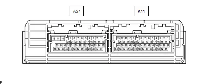
CHECK CERTIFICATION ECU (SMART KEY ECU ASSEMBLY)
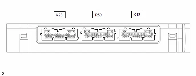
(a) Disconnect the K23 and K13 certification ECU (smart key ECU assembly) connectors.
(b) Measure the resistance and voltage according to the value(s) in the table below.
HINT:
Measure the values on the wire harness side with the connector disconnected.
| Tester Connection | Terminal Description | Condition | Specified Condition | Related Data List Item/DTC |
|---|---|---|---|---|
| K23-21 (STP1) - Body ground | Stop light switch signal | Brake pedal depressed → Brake pedal released | 9 V or higher → 1 V or less | Power Source Control
|
| K13-6 ( B) - K13-29 (E) | Power source | Ignition switch off | 11 to 14 V | - |
| K13-14 (P) - K13-29 (E) | P position signal | Always | 30 kΩ or higher | Power Source Control
|
| K23-22 (CUTB) - Body ground | Dark current cut pin* | Ignition switch off | 11 to 14 V | - |
| K13-29 (E) - Body ground | GND | Always | Below 1 Ω | - |
| K13-11 (SLP) - K13-29 (E) | GND | Always | Below 1 Ω | - |
| K13-23 (SSW3) - Body ground | SSW3 contact signal | Power switch pushed → Power switch not pushed | Below 15 Ω → 10 kΩ or higher | Power Source Control
|
| K13-27 (SSW2) - Body ground | SSW2 contact signal | Power switch pushed → Power switch not pushed | Below 15 Ω → 10 kΩ or higher | Power Source Control
|
| K13-19 (SSW1) - Body ground | SSW1 contact signal | Power switch pushed → Power switch not pushed | Below 15 Ω → 10 kΩ or higher | Power Source Control
|
- *: In order to prevent the Toyota Prius vehicle auxiliary battery from being depleted when the vehicle is shipped long distances, a fuse that cuts unnecessary electrical load while the vehicle is being shipped is installed in the circuit. If the fuse is removed, the circuit becomes open. If the fuse that is between the vehicle auxiliary battery and terminal CUTB is removed and the circuit is open, the certification ECU (smart key ECU assembly) changes to a certain control mode (example: the transmission of radio waves every 0.25 seconds, which form the detection area, stops).
(c) Connect the K23 and K13 certification ECU (smart key ECU assembly) connectors.
(d) Measure the voltage and resistance, and check for pulses according to the value(s) in the table below.
| Tester Connection | Terminal Description | Condition | Specified Condition | Related Data List Item/DTC |
|---|---|---|---|---|
| K13-8 (LIN) - K13-29 (E) | LIN communication line | Ignition switch ON | Pulse generation | - |
| K13-14 (P) - K13-29 (E) | P position signal | Ignition switch ON and Shift position in P | Pulse generation (24 to 25 Hz or 30 to 31 Hz, High voltage: 9 V or more, Low voltage: below 1 V, duty ratio: 25 %) | Power Source Control
|
| Ignition switch ON and Shift position in N | Pulse generation (24 to 25 Hz or 30 to 31 Hz, High voltage: 9 V or more, Low voltage: below 1 V, duty ratio: 55 %) | |||
| Ignition switch ON and Shift position in other then P or N | Pulse generation (24 to 25 Hz or 30 to 31 Hz, High voltage: 9 V or more, Low voltage: below 1 V, duty ratio: 40 %) | |||
| K13-23 (SSW3) - K13-29 (E) | SSW3 contact signal | Power switch not pushed → Power switch pushed | 9 V or higher → 1 V or less | Power Source Control
|
| K13-27 (SSW2) - K13-29 (E) | SSW2 contact signal | Power switch not pushed → Power switch pushed | 9 V or higher → 1 V or less | Power Source Control
|
| K13-19 (SSW1) - K13-29 (E) | SSW1 contact signal | Power switch not pushed → Power switch pushed | 9 V or higher → 1 V or less | Power Source Control
|
| K13-21 (ACCD) - K13-29 (E) | ACC signal | Ignition switch off → Ignition switch ACC | 1 V or less → 8.5 V or higher | Power Source Control
|
| K23-11 (IGRD) - K13-29 (E) | IG signal | Ignition switch off → Ignition switch ON | 1 V or less → 9 V or higher | Power Source Control
|
| K23-24 (IGPD) - K13-29 (E) | IG signal | Ignition switch off → Ignition switch ON | 1 V or less → 9 V or higher | Power Source Control
|
| K23-13 (SPD) - K13-29 (E) | Toyota Prius Vehicle speed signal | Vehicle being driven at approx. 5 km/h (3 mph) | Pulse generation (See waveform 1) | Power Source Control
|
| K23-2 (ST2) - K13-29 (E) | STSW signal | With the brake pedal depressed, the power switch is pressed and held → After approx. 3 sec. has elapsed, the power switch is released | 8.5 V or higher → 1 V or less | - |
| K13-4 (CLG5) - K13-29 (E) | Output to No. 1 indoor electrical key antenna assembly (front floor) | Procedure:
| Pulse generation (See waveform 2) | - |
| K13-5 (CG5B) - K13-29 (E) | Output to No. 1 indoor electrical key antenna assembly (front floor) (terminal on opposite side of component from CLG5 output terminal) | Procedure:
| Pulse generation (See waveform 2) | - |
| R59-10 (CLG7) - K13-29 (E) | Output to No. 2 indoor electrical key antenna assembly (rear floor) | Procedure:
| Pulse generation (See waveform 2) | - |
| R59-9 (CG7B) - K13-29 (E) | Output to No. 2 indoor electrical key antenna assembly (rear floor) (terminal on opposite side of component from CLG7 output terminal) | Procedure:
| Pulse generation (See waveform 2) | - |
| K13-30 (AGND) - Body ground | Transponder key amplifier ground | Always | Below 1 Ω | - |
| K13-12 (ANT1) - K13-30 (AGND) | Signal input / output from transponder key coil (transponder key coil built into power switch) | Ignition switch off, electrical key transmitter sub-assembly not in cabin, within 30 seconds of power switch pressed | Pulse generation (Type A: See waveform 3, Type B: See waveform 5) | Smart Key
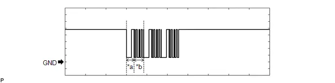
|
| K13-13 (ANT2) - K13-30 (AGND) | Signal input / output from transponder key coil (transponder key coil built into power switch) | Ignition switch off, electrical key transmitter sub-assembly not in cabin, within 30 seconds of power switch pressed | Pulse generation (Type A: See waveform 4, Type B: See waveform 5) | |
| K13-25 (IND) - K13-29 (E) | Security indicator output | Ignition switch off → ON | Pulse generation → Below 2 V | - |
| R59-20 (WCSW) - K13-29 (E)* | Wireless charger system stop signal | Procedure:
| Below 1 V → 4.5 to 6 V (For 1 second after ignition switch to ACC or ON) | - |
- *: w/ Wireless Charging System
(e) Using an oscilloscope, check the waveform of the ECU.
NOTICE:
The oscilloscope waveform shown in the illustration is an example for reference only. Noise, chattering, etc. are not shown.
(1) Waveform 1
 Measurement Condition
 | Item | Content |
|---|---|
| Tester Connection | K23-13 (SPD) - K13-29 (E) |
| Tool Setting | 5 V/DIV., 20 ms./DIV. |
| Condition | Toyota Prius Vehicle being driven at approx. 5 km/h (3 mph) |
HINT:
The wavelength becomes shorter as the vehicle speed increases.
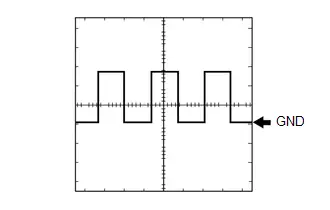
(2) Waveform 2
Type A: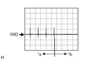
| *a | For 30 seconds after any door closed |
| *b | After 30 seconds or more have elapsed since any door closed |
| Item | Content |
|---|---|
| Tester Connection | K13-4 (CLG5) - K13-29 (E) K13-5 (CG5B) - K13-29 (E) R59-10 (CLG7) - K13-29 (E) R59-9 (CG7B) - K13-29 (E) |
| Tool Setting | 5 V/DIV., 500 ms/DIV. |
| Condition | Procedure:
|
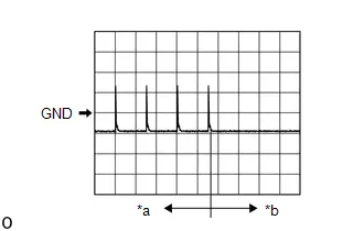
| *a | For 30 seconds after any door closed |
| *b | After 30 seconds or more have elapsed since any door closed |
(3) Waveform 3 (Type A)
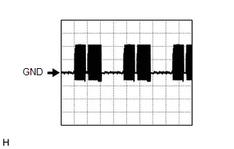 Measurement Condition
 | Item | Content |
|---|---|
| Tester Connection | K13-12 (ANT1) - K13-30 (AGND) |
| Tool Setting | 5 V/DIV., 200 ms./DIV. |
| Condition | Ignition switch off, electrical key transmitter sub-assembly not in cabin, within 30 seconds of power switch pressed |
(4) Waveform 4 (Type A)
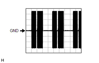 Measurement Condition
 | Item | Content |
|---|---|
| Tester Connection | K13-13 (ANT2) - K13-30 (AGND) |
| Tool Setting | 20 V/DIV., 200 ms/DIV. |
| Condition | Ignition switch off, electrical key transmitter sub-assembly not in cabin, within 30 seconds of power switch pressed |
(5) Waveform 5 (Type B)
 Measurement Condition
 | Item | Content |
|---|---|
| Tester Connection | K13-13 (ANT2) - K13-30 (AGND) |
| Tool Setting | 20 V/DIV., 200 ms/DIV. |
| Condition | Ignition switch off, electrical key transmitter sub-assembly not in cabin, within 30 seconds of power switch pressed |
CHECK ID CODE BOX (IMMOBILISER CODE ECU)

(a) Disconnect the K43 ID code box (immobiliser code ECU) connector.
(b) Measure the voltage and resistance according to the value(s) in the table below.
HINT:
Measure the values on the wire harness side with the connector disconnected.
| Tester Connection | Terminal Description | Condition | Specified Condition | Related Data List Item |
|---|---|---|---|---|
| K43-1 ( B) - Body ground | Power source | Ignition switch off | 11 to 14 V | - |
| K43-5 (GND) - Body ground | Ground | Always | Below 1 Ω |
(c) Connect the K43 ID code box (immobiliser code ECU) connector.
(d) Measure the voltage and check for pulses according to the value(s) in the table below.
| Tester Connection | Terminal Description | Condition | Specified Condition | Related Data List Item |
|---|---|---|---|---|
| K43-3 (EFII) - K43-5 (GND) | EFI communication input (Signal input from hybrid Toyota Prius vehicle control ECU to ID code box (immobiliser code ECU)) | Ignition switch off | 11 to 14 V | Smart Key
|
| K43-3 (EFII) - K43-5 (GND) | EFI communication input (Signal input from hybrid Toyota Prius vehicle control ECU to ID code box (immobiliser code ECU)) | Within 3 seconds of hybrid control system start or within 3 seconds of ignition switch turned to ON after cable disconnected and reconnected to auxiliary battery | Pulse generation (See waveform 1) | |
| K43-4 (EFIO) - K43-5 (GND) | EFI communication output (Signal output from ID code box (immobiliser code ECU) to hybrid Toyota Prius vehicle control ECU) | Ignition switch off | Below 1 V | |
| K43-4 (EFIO) - K43-5 (GND) | EFI communication output (Signal output from ID code box (immobiliser code ECU) to hybrid Toyota Prius vehicle control ECU) | Within 3 seconds of hybrid control system start or within 3 seconds of ignition switch turned to ON after cable disconnected and reconnected to auxiliary battery | Pulse generation (See waveform 2) | |
| K43-2 (LIN1) - K43-5 (GND) | LIN communication line | Ignition switch ON | Pulse generation | - |
(e) Using an oscilloscope, check the waveform.
NOTICE:
The waveform shown in the illustration is an example for reference only. Noise, chattering, etc. are not shown.
(1) Waveform 1
| *a | Approximately 160 ms. | *b | Approximately 270 ms. |
| Item | Content |
|---|---|
| Tester Connection | K43-3 (EFII) - K43-5 (GND) |
| Tool Setting | 2 V/DIV., 500 ms./DIV. |
| Condition | Within 3 seconds of hybrid control system start or within 3 seconds of ignition switch turned to ON after cable disconnected and reconnected to auxiliary battery |
(2) Waveform 2

| *a | Approximately 160 ms. | *b | Approximately 270 ms. |
| Item | Content |
|---|---|
| Tester Connection | K43-4 (EFIO) - K43-5 (GND) |
| Tool Setting | 2 V/DIV., 500 ms./DIV. |
| Condition | Within 3 seconds of hybrid control system start or within 3 seconds of ignition switch turned to ON after cable disconnected and reconnected to auxiliary battery |
CHECK HYBRID Toyota Prius Vehicle CONTROL ECU
(a) Measure the voltage and resistance, and check for pulses according to the value(s) in the table below.
| Terminal No. (Symbol) | Terminal Description | Condition | Specified Condition | Related Data List Item/DTC |
|---|---|---|---|---|
| K11-26 (IGP) - K11-1 (E1) | Ignition power supply | Ignition switch ON | 11 to 14 V | - |
| A57-8 (IGR) - K11-1 (E1) | Ignition power supply | Ignition switch ON | 11 to 14 V | - |
| K11-1 (E1) - Body ground | Ground | Always | Below 1 Ω | - |
| K11-39 (IMO) - K11-1 (E1) | EFI communication output (Signal output from hybrid Toyota Prius vehicle control ECU to ID code box (immobiliser code ECU)) | Ignition switch off | 11 to 14 V |
|
| K11-39 (IMO) - K11-1 (E1) | EFI communication output (Signal output from hybrid Toyota Prius vehicle control ECU to ID code box (immobiliser code ECU)) | Within 3 seconds of hybrid control system start or within 3 seconds of ignition switch turned to ON after cable disconnected and reconnected to auxiliary battery | Pulse generation (See waveform 1) | |
| K11-53 (IMI) - K11-1 (E1) | EFI communication input (Signal input from ID code box (immobiliser code ECU) to hybrid Toyota Prius vehicle control ECU) | Ignition switch off | 11 to 14 V → 1 V or less | |
| K11-53 (IMI) - K11-1 (E1) | EFI communication input (Signal input from ID code box (immobiliser code ECU) to hybrid Toyota Prius vehicle control ECU) | Within 3 seconds of hybrid control system start or within 3 seconds of ignition switch turned to ON after cable disconnected and reconnected to auxiliary battery | Pulse generation (See waveform 2) | |
| K11-11 (ST2) - K11-1 (E1) | Hybrid control system start request signal | With the brake pedal depressed, the power switch is pressed and held → After approx. 3 sec. has elapsed, the power switch is released | 8.5 V or higher → 1.0 V or less | - |
(b) Using an oscilloscope, check the waveform.
NOTICE:
The waveform shown in the illustration is an example for reference only. Noise, chattering, etc. are not shown.
(1) Waveform 1 (Reference)
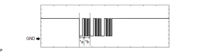
| *a | Approximately 160 ms. | *b | Approximately 270 ms. |
| Item | Content |
|---|---|
| Tester Connection | K11-39 (IMO) - K11-1 (E1) |
| Tool Setting | 2 V/DIV., 500 ms./DIV. |
| Condition | Within 3 seconds of hybrid control system start or within 3 seconds of ignition switch turned to ON after cable disconnected and reconnected to auxiliary battery |
(2) Waveform 2 (Reference)
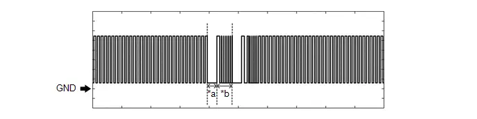
| *a | Approximately 160 ms. | *b | Approximately 270 ms. |
| Item | Content |
|---|---|
| Tester Connection | K11-53 (IMI) - K11-1 (E1) |
| Tool Setting | 2 V/DIV., 500 ms./DIV. |
| Condition | Within 3 seconds of hybrid control system start or within 3 seconds of ignition switch turned to ON after cable disconnected and reconnected to auxiliary battery |
CHECK POWER SWITCH

(a) Measure the resistance according to the value(s) in the table below.
| Terminal No. (Symbol) | Terminal Description | Condition | Specified Condition | Related Data List Item/DTC |
|---|---|---|---|---|
| K66-3 (GND) - Body ground | Transponder key amplifier ground | Always | Below 1 Ω | - |
(b) Measure the voltage and check for pulses according to the value(s) in the table below.
| Terminal No. (Symbol) | Terminal Description | Condition | Specified Condition | Related Data List Item/DTC |
|---|---|---|---|---|
| K66-1 (ANT1) - K66-3 (GND) | Signal input / output from transponder key coil (transponder key coil built into power switch) | Ignition switch off, electrical key transmitter sub-assembly not in cabin, within 30 seconds of power switch pressed | Pulse generation (Type A: See waveform 1, Type B: See waveform 3) | Smart Key
|
| K66-7 (ANT2) - K66-3 (GND) | Signal input / output from transponder key coil (transponder key coil built into power switch) | Ignition switch off, electrical key transmitter sub-assembly not in cabin, within 30 seconds of power switch pressed | Pulse generation (Type A: See waveform 2, Type B: See waveform 3) | |
| K66-11 (SS3) - K66-3 (GND) | SS3 contact signal HINT: Backup for SS1. Behaves the same way as SS1. | Power switch not pushed → Power switch pushed | 9 V or higher → Below 1 V | Power Source Control
|
| K66-6 (SS2) - K66-3 (GND) | SS2 contact signal HINT: Backup for SS1. Behaves the same way as SS1. | Power switch not pushed → Power switch pushed | 9 V or higher → Below 1 V | Power Source Control
|
| K66-12 (SS1) - K66-3 (GND) | SS1 contact signal | Power switch not pushed → Power switch pushed | 9 V or higher → Below 1 V | Power Source Control
|
(c) Using an oscilloscope, check the waveform.
NOTICE:
The waveform shown in the illustration is an example for reference only. Noise, chattering, etc. are not shown.
(1) Waveform 1 (Reference) (Type A)
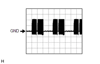 Measurement Condition
 | Item | Content |
|---|---|
| Tester Connection | K66-1 (ANT1) - K66-3 (GND) |
| Tool Setting | 5 V/DIV., 200 ms./DIV. |
| Condition | Ignition switch off, electrical key transmitter sub-assembly not in cabin, within 30 seconds of power switch pressed |
(2) Waveform 2 (Reference) (Type A)
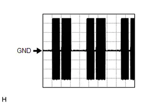 Measurement Condition
 | Item | Content |
|---|---|
| Tester Connection | K66-7 (ANT2) - K66-3 (GND) |
| Tool Setting | 20 V/DIV., 200 ms./DIV. |
| Condition | Ignition switch off, electrical key transmitter sub-assembly not in cabin, within 30 seconds of power switch pressed |
(3) Waveform 3 (Reference) (Type B)
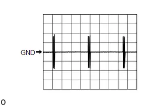 Measurement Condition
 | Item | Content |
|---|---|
| Tester Connection | K66-1 (ANT1) - K66-3 (GND) K66-7 (ANT2) - K66-3 (GND) |
| Tool Setting | 20 V/DIV., 200 ms./DIV. |
| Condition | Ignition switch off, electrical key transmitter sub-assembly not in cabin, within 30 seconds of power switch pressed |
SMART KEY SYSTEM (for Entry Function)
Click here

Data List / Active Test
DATA LIST / ACTIVE TEST
DATA LIST
NOTICE:
- In the table below, the values listed under "Normal Condition" are reference values. Do not depend solely on these reference values when deciding whether a part is faulty or not.
-
When performing an inspection, make sure that "ACC Customize" is set to "ON" using the multi-display.
Click here

-
When "ACC Customize" is set to "ON" (ACC supply power enabled), the certification ECU (smart key ECU assembly) controls the ACC relay on and off. When "ACC Customize" is set to "OFF" (ACC supply power disabled), the certification ECU (smart key ECU assembly) and radio and display receiver assembly control the ACC relay on and off.
Therefore, inspection conditions and results may differ depending on whether "ACC customize" is set to ON or OFF when inspecting the Data List.
HINT:
Using the GTS to read the Data List allows the values or states of switches, sensors, actuators and other items to be read without removing any parts. This non-intrusive inspection can be very useful because intermittent conditions or signals may be discovered before parts or wiring is disturbed. Reading the Data List information early in troubleshooting is one way to save diagnostic time.
(a) Connect the GTS to the DLC3.
(b) Turn the ignition switch to ON.
(c) Turn the GTS on.
(d) Enter the following menus: Body Electrical / (desired system) / Data List.
(e) Read the Data List according to the display on the GTS.
Body Electrical > Power Source Control > Data List| Tester Display | Measurement Item | Range | Normal Condition | Diagnostic Note |
|---|---|---|---|---|
| Total Distance Traveled | Total distance traveled | Min.: 0 Max.: 999999 | Actual total distance displayed | - |
| Total Distance Traveled - Unit | Total distance traveled unit | km or mile | - | - |
| Push Start Switch 1 | Power switch 1 status | OFF or ON | OFF: Power switch not pressed ON: Power switch pressed |
|
| Push Start Switch 2 | Power switch 2 status | OFF or ON | OFF: Power switch not pressed ON: Power switch pressed |
|
| Push Start Switch 3 | Power switch 3 status | OFF or ON | OFF: Power switch not pressed ON: Power switch pressed |
|
| Steering Unlock Switch | - | - | - | Although the item is displayed on the GTS, it is not applicable to this Toyota Prius vehicle. |
| Shift P Signal | - | - | - | Although the item is displayed on the GTS, it is not applicable to this Toyota Prius vehicle. |
| Stop Light Switch | State of brake pedal | OFF or ON | OFF: Brake pedal released ON: Brake pedal depressed |
|
| IGP Relay Circuit (Outside) Monitor | IGP relay coil voltage monitor status | OFF or ON | OFF: Ignition switch off ON: Ignition switch ON |
|
| IGP Relay Circuit (Inside) Monitor | IGP relay activation | OFF or ON | OFF: Ignition switch off ON: Ignition switch ON |
|
| IGR Relay Circuit (Outside) Monitor | IGR relay coil voltage monitor status | OFF or ON | OFF: Ignition switch off ON: Ignition switch ON |
|
| IGR Relay Circuit (Inside) Monitor | IGR relay activation | OFF or ON | OFF: Ignition switch off ON: Ignition switch ON |
|
| IGP Hold Circuit Monitor | IGP relay hold monitor status | OFF or ON | OFF: Ignition switch off ON: Ignition switch ON | - |
| ACC Relay Monitor | ACC relay activation | OFF or ON | OFF: Ignition switch off ON: Ignition switch ACC | When the ignition switch is ON, ON is displayed. |
| IGB Relay Monitor | - | - | - | Although the item is displayed on the GTS, it is not applicable to this Toyota Prius vehicle. |
| Vehicle Running Condition (Line) | Vehicle being driven or stopped | Stop or Running | Stop: Vehicle stopped Running: Toyota Prius Vehicle being driven at 5 km/h (3 mph) or more | - |
| IGB Output Condition | - | - | - | Although the item is displayed on the GTS, it is not applicable to this Toyota Prius vehicle. |
| IGBD Condition | - | - | - | Although the item is displayed on the GTS, it is not applicable to this Toyota Prius vehicle. |
| Power Supply Condition | Power supply state | OFF, ACC ON, IGR ON, IGP ON or Starter ON | OFF: Ignition switch off ACC ON: Ignition switch ACC IGR ON: Ignition switch ON IGP ON: Ignition switch ON Starter ON: Sending hybrid control system start request signal | - |
| Shift P Signal Condition (Line) | Shift position P | Shift P, Other than shift P, Shift N or Other than shift P/N | Shift P: Shift position in P Shift N: Shift position in N Other than shift P/N: Other than shift position in P or N | Use this item to determine if the shift position switch is malfunctioning. |
| Powertrain Type | Toyota Prius Vehicle identification | Cnv-MT, Cnv-AT, Cnv-MMT, S&S-MT, S&S-AT, S&S-MMT, HV/FCHV-AT, PHV/EV-AT or 1Motor HV-AT | HV/FCHV-AT: Hybrid control system models | - |
| Shift P Signal Mismatch | P position signal malfunction | Not Detected or Detected | Not Detected: Signal normal Detected: Signal malfunction (signals via CAN communication and direct line do not match) | Even when Detected is displayed, it is still possible to turn the ignition switch off (the power source mode will not be stuck in ACC or ON). |
| Steering Lock - Unlock Time Out | - | - | - | Although the item is displayed on the GTS, it is not applicable to this Toyota Prius vehicle. |
| Key Certification Time Out | Key verification malfunction | Not Detected or Detected | Not Detected: Verification normal Detected: Verification error (Detected due to the electrical key transmitter sub-assembly ID code and the ID code stored in the certification ECU (smart key ECU assembly) not matching) | When the hybrid control system cannot be started due to a key verification error, Yes is displayed. |
| IGR Relay Circuit (Outside) Malfunction | IGR relay coil circuit malfunction | Not Detected or Detected | Not Detected: Circuit normal Detected: Circuit malfunctioning |
|
| IGP Relay Circuit (Outside) Malfunction | IGP relay coil circuit malfunction | Not Detected or Detected | Not Detected: Circuit normal Detected: Circuit malfunctioning |
|
| Auto Power OFF Cancel Mode | - | - | - | Although the item is displayed on the GTS, it is not applicable to this Toyota Prius vehicle. |
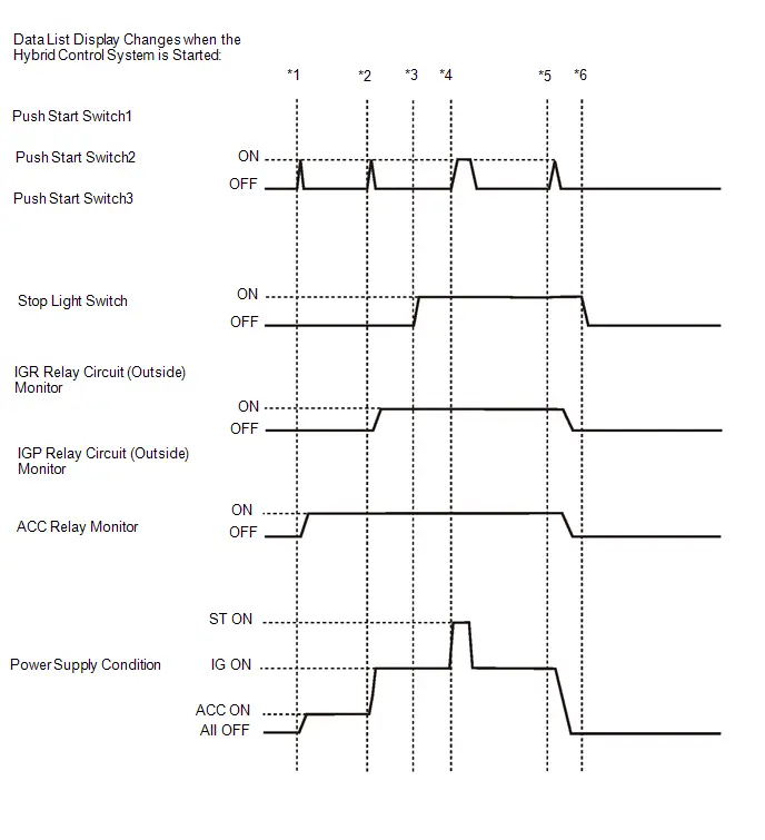 To check if the Data List display changes, get into the vehicle while carrying an electrical key transmitter sub-assembly and perform the following operations with the ignition switch off and the shift position in P.
 - *1: Press the power switch with the brake pedal released and check that the ignition switch turns ACC.
- *2: Press the power switch with the brake pedal released and check that the ignition switch turns ON.
- *3: Depress the brake pedal (stop light switch assembly is on).
- *4: Press the power switch with the brake pedal depressed and check that the hybrid control system starts.
- *5: Press the power switch with the brake pedal depressed and check that the ignition switch turns off.
- *6: Release the brake pedal.
| Tester Display | Measurement Item | Range | Normal Condition | Diagnostic Note |
|---|---|---|---|---|
| Cut Fuse | Cut fuse installed | OFF or ON | OFF: Cut fuse not installed ON: Cut fuse installed | - |
| Electronic Key No Response | Communication response | No or Yes | No: Communication normal Yes: Communication malfunction | The Toyota Prius vehicle IDs registered in the vehicle and electrical key transmitter sub-assembly match, but there is no response from the electrical key transmitter sub-assembly. (If the electrical key transmitter sub-assembly is not in the detection area or the transmitter battery is depleted resulting in a matching code not being detected when a lock switch or the power switch is pressed, etc., "Yes" is displayed for "No Response" in the Data List. If there is wave interference in the LF band that the Toyota Prius vehicle uses for transmission or the RF band that the electrical key transmitter sub-assembly uses for transmission, "Yes" may be displayed for "No Response" in the Data List.) Other potential causes:
|
| Key Low Battery | Transmitter battery depleted | No or Yes | No: Transmitter battery not depleted Yes: Transmitter battery depleted | The electrical key transmitter sub-assembly sends voltage information to the certification ECU (smart key ECU assembly) when it is transmitting. "Yes" is displayed for the Data List item "Key Low Battery" when this voltage information indicates 2.2 V or less. This Data List item should be checked when the electrical key transmitter sub-assembly is at room temperature (example: at -20°C (-4°F), "Yes" may be displayed even if the transmitter battery is new). |
| B Code Difference | B code mismatch | No or Yes | No: Communication normal Yes: Communication malfunction | - |
| B Code Registered | B code registration status | No or Yes | No: B code not registered correctly Yes: B code registered correctly | - |
| Immobiliser | Immobiliser system status determined by certification ECU (smart key ECU assembly)*5 | Set or Unset | Set: Immobiliser set (hybrid control system start prohibited) (ignition switch off) Unset: Immobiliser unset (hybrid control system start permitted) (ignition switch ACC or ON) | The hybrid control system cannot be started when Set is displayed. HINT:
|
| Immobiliser when IG=ON | Immobiliser function status when ignition switch ON | Unset or Set | Unset: Immobiliser function not set with ignition switch ON or immobiliser function unset 40 times after immobiliser function set Set: Immobiliser function set (driver door opened and closed with ignition switch ON) | - |
| Master Key | Matching of master key ID code and ID code registered in certification ECU (smart key ECU assembly) | No or Yes | No: ID code of master key does not match ID code registered in certification ECU (smart key ECU assembly) Yes: ID code of master key matches ID code registered in certification ECU (smart key ECU assembly) | - |
| Sub Key | Matching of sub key ID code and ID code registered in certification ECU (smart key ECU assembly) | No or Yes | No: ID code of sub key does not match ID code registered in certification ECU (smart key ECU assembly) Yes: ID code of sub key matches ID code registered in certification ECU (smart key ECU assembly) | - |
| BCC Malfunction | Type A:
| No or Yes | No: BCC signal normal Yes: BCC signal malfunction (malfunction in code computation in electrical key transmitter sub-assembly/certification ECU (smart key ECU assembly)) | Problems may be caused by the following:
|
| Abnormal Status | Type A:
| No or Yes | No: Transponder chip status signal normal Yes: Transponder chip status signal malfunction (malfunction in code computation in electrical key transmitter sub-assembly/certification ECU (smart key ECU assembly)) | Problems may be caused by the following:
|
| Encrypt Code Difference | Matching of transponder chip code and certification ECU (smart key ECU assembly) code*1 | No or Yes | No: Codes of transponder chip and certification ECU (smart key ECU assembly) match Yes: Codes of transponder chip and certification ECU (smart key ECU assembly) do not match | Problems may be caused by the following:
|
| Different Serial Number | Type A:
| No or Yes | No: Signal from transponder chip and vehicle serial number stored in the certification ECU (smart key ECU assembly) match Yes: Signal from transponder chip and Toyota Prius vehicle serial number stored in the certification ECU (smart key ECU assembly) do not match | Problems may be caused by the following:
|
| Frame Error | Type A:
| No or Yes | No: No problem with data sent from electrical key transmitter sub-assembly Yes: Problem with data sent from electrical key transmitter sub-assembly | Problems may be caused by the following:
|
| No Response | Type A:
| No or Yes | No: Electrical key transmitter sub-assembly responds to signal from certification ECU (smart key ECU assembly) Yes: Electrical key transmitter sub-assembly does not respond to signal from certification ECU (smart key ECU assembly) | Problems may be caused by the following:
|
| Steering Lock Sleep Condition | - | - | - | Although the item is displayed on the GTS, it is not applicable to this Toyota Prius vehicle. |
| Steering Lock Start Condition | - | - | - | Although the item is displayed on the GTS, it is not applicable to this Toyota Prius vehicle. |
| Steering Lock Data Fix | - | - | - | Although the item is displayed on the GTS, it is not applicable to this Toyota Prius vehicle. |
| Start Condition | - | - | - | Although the item is displayed on the GTS, it is not applicable to this Toyota Prius vehicle. |
| Sensor Malfunction History | - | - | - | Although the item is displayed on the GTS, it is not applicable to this Toyota Prius vehicle. |
| Power Supply Short History | - | - | - | Although the item is displayed on the GTS, it is not applicable to this Toyota Prius vehicle. |
| Motor Driver Short History | - | - | - | Although the item is displayed on the GTS, it is not applicable to this Toyota Prius vehicle. |
| Lock/Unlock Receive History | - | - | - | Although the item is displayed on the GTS, it is not applicable to this Toyota Prius vehicle. |
| Lock Bar Stuck Error History | - | - | - | Although the item is displayed on the GTS, it is not applicable to this Toyota Prius vehicle. |
| Data Access Error | - | - | - | Although the item is displayed on the GTS, it is not applicable to this Toyota Prius vehicle. |
| Open in IG2 History | - | - | - | Although the item is displayed on the GTS, it is not applicable to this Toyota Prius vehicle. |
| ID-BOX Sleep Condition | ID code box (immobiliser code ECU) sleep mode status*5 | No or Yes | No: ID code box (immobiliser code ECU) sleep mode not possible Yes: ID code box (immobiliser code ECU) sleep mode possible | - |
| ID-BOX Start Condition | ID code box (immobiliser code ECU) status*2 | No or Yes | No: Wake-up signal not sent by ID code box (immobiliser code ECU) Yes: Wake-up signal sent by ID code box (immobiliser code ECU) | - |
| EFI Code Receive | Certification information sent to ID code box (immobiliser code ECU) from hybrid Toyota Prius vehicle control ECU when hybrid vehicle control ECU receives hybrid control system start permission signal from ID code box (immobiliser code ECU)*3,*5 | OK or NG | OK: Signal from hybrid vehicle control ECU to unset immobiliser received by ID code box (immobiliser code ECU) NG: Signal from hybrid Toyota Prius vehicle control ECU to unset immobiliser not received by ID code box (immobiliser code ECU) | - |
| Start Request | Immobiliser unset (hybrid control system start permitted) signal from certification ECU (smart key ECU assembly) to ID code box (immobiliser code ECU) received state*5 | OK or NG | OK: Signal received NG: Signal not received |
|
| 12bit Code Request Receive | 12-bit code request condition | OK or NG | OK: 12-bit code request condition signal received NG: 12-bit code request condition signal not received | - |
| S Code Check | Verification result between certification ECU (smart key ECU assembly) and ID code box (immobiliser code ECU)*4 | OK or NG | OK: Verification result normal NG: Verification result abnormal | When NG is displayed:
|
| L Code Check | Status of L code registered in the ID code box (immobiliser code ECU) | OK or NG | OK: Normal NG: Abnormal | When NG is displayed:
|
| Steering Unlock Request Receive | - | - | - | Although the item is displayed on the GTS, it is not applicable to this Toyota Prius vehicle. |
| Steering Lock Request Receive | - | - | - | Although the item is displayed on the GTS, it is not applicable to this Toyota Prius vehicle. |
| EFI Communication | State of communication to unset immobiliser between certification ECU (smart key ECU assembly) and hybrid vehicle control ECU | NG or OK | NG: Communication to unset immobiliser has not started between certification ECU (smart key ECU assembly) and hybrid Toyota Prius vehicle control ECU OK: Communication to unset immobiliser has started between certification ECU (smart key ECU assembly) and hybrid vehicle control ECU | If this item displays "NG" even though the conditions to unset the immobiliser have been met and the value of Data List item "Start Request" is "OK", the hybrid Toyota Prius vehicle control ECU may be malfunctioning. When the hybrid control system cannot be started, use this Data List item during troubleshooting. |
| S Code Check (Past) | Verification result history between the certification ECU (smart key ECU assembly) and ID code box (immobiliser code ECU) | OK or NG | OK: History of abnormal verification result does not exist NG: History of abnormal verification result exists | - |
| L Code Check (Past) | History of code in ID code box (immobiliser code ECU) | OK or NG | OK: History of abnormal verification result does not exist NG: History of abnormal verification result exists | - |
| EFI Communication Code Status | Status of EFI communication code | OK or NG | OK: Signal from hybrid Toyota Prius vehicle control ECU was correct NG: Signal from hybrid vehicle control ECU was incorrect | - |
| EFI Communication Status | Status of EFI communication | OK or NG | OK: Communication normal between certification ECU (smart key ECU assembly) and hybrid Toyota Prius vehicle control ECU NG: Communication malfunction between certification ECU (smart key ECU assembly) and hybrid vehicle control ECU | - |
| EFI Communication Speed | Status of EFI communication speed | OK or NG | OK: Communication speed normal NG: Communication speed abnormal | - |
| ID-Box Wait Status | Wait status of ID code box | Normal or Waiting | Normal: ID code box not waiting Waiting: ID code box waiting | - |
| S/L Code Registration Error History | Status of S/L code registration | OFF or ON | OFF: S/L code registration was completed normally ON: S/L code registration was not completed normally | - |
| Number of Registered Key Codes | Number of registered electrical key transmitter sub-assemblies | Type A:
Type B:
| Number of registered electrical key transmitter sub-assemblies | Type A:
Type B:
|
| Start Switch Light Function | Power switch light | OFF or ON | Customize setting displayed | - |
HINT:
- *1: This indicates that there is a problem with the communication format between the electrical key transmitter sub-assembly and certification ECU (smart key ECU assembly). Wave interference, malfunction of the electrical key transmitter sub-assembly or certification ECU (smart key ECU assembly), an electrical key transmitter sub-assembly from different Toyota Prius vehicle being used, etc. are possible causes.
- *2: This indicates that transmission of the wake-up signal is possible ("Yes" indicates that the signal to begin verification-related LIN communication is being sent). When communication is being performed between the certification ECU (smart key ECU assembly) and hybrid Toyota Prius vehicle control ECU, the display changes to "Yes".
- *3: This indicates that the hybrid control system start permission request signal (EGST) output from the hybrid vehicle control ECU is being received by the ID code box (immobiliser code ECU).
- *4: This indicates the certification result of the certification codes of the certification ECU (smart key ECU assembly) and ID code box (immobiliser code ECU).
- *5: Refer to the following Data List items when inspecting the actual Toyota Prius vehicle.
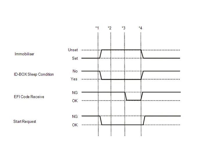 To check if the Data List display changes, get into the vehicle while carrying an electrical key transmitter sub-assembly and perform the following operations with the ignition switch off and the shift position in P.
 - *1: Press the power switch with the brake pedal released and check that the ignition switch turns ACC.
- *2: Press the power switch with the brake pedal released and check that the ignition switch turns ON.
- *3: Press the power switch with the brake pedal released and check that the power starts.
- *4: Press the power switch and check that the ignition switch turns off.
| Tester Display | Measurement Item | Range | Normal Condition | Diagnostic Note |
|---|---|---|---|---|
| Toyota Prius Vehicle Speed Meter | Vehicle speed | Min.: 0, Max.: 255 | Almost same as actual vehicle speed (Speedometer tester) | - |
| Tester Display | Measurement Item | Range | Normal Condition | Diagnostic Note |
|---|---|---|---|---|
| Toyota Prius Vehicle Speed | Vehicle speed | Min.: 0.0 km/h (0 mph) Max.: 6553.5 km/h (4072 mph) | Vehicle stopped: 0.0 km/h (0 mph) | When driving at constant speed: No large fluctuations |
| Tester Display | Measurement Item | Range | Normal Condition | Diagnostic Note |
|---|---|---|---|---|
| FR Door Courtesy Switch Status | Front door RH courtesy light switch signal | Close or Open | Close: Front door RH closed Open: Front door RH open | - |
| FL Door Courtesy Switch Status | Front door LH courtesy light switch signal | Close or Open | Close: Front door LH closed Open: Front door LH open | - |
| RR Door Courtesy Switch Status | Rear door RH courtesy light switch signal | Close or Open | Close: Rear door RH closed Open: Rear door RH open | - |
| RL Door Courtesy Switch Status | Rear door LH courtesy light switch signal | Close or Open | Close: Rear door LH closed Open: Rear door LH open | - |
| Tester Display | Measurement Item | Range | Normal Condition | Diagnostic Note |
|---|---|---|---|---|
| Stop Light Switch | Brake pedal signal | OFF or ON | OFF: Brake pedal released ON: Brake pedal depressed | - |
ACTIVE TEST
HINT:
Using the GTS to perform Active Tests allows relays, VSVs, actuators and other items to be operated without removing any parts. This non-intrusive functional inspection can be very useful because intermittent operation may be discovered before parts or wiring is disturbed. Performing Active Tests early in troubleshooting is one way to save diagnostic time. Data List information can be displayed while performing Active Tests.
(a) Connect the GTS to the DLC3.
(b) Turn the ignition switch to ON.
(c) Turn the GTS on.
(d) Enter the following menus: Body Electrical / Smart Key / Active Test.
(e) Perform Active Test according to the display on the GTS.
Body Electrical > Smart Key > Active Test| Tester Display | Measurement Item | Control Range | Diagnostic Note |
|---|---|---|---|
| Start SW Light Power Supply | Power switch light | OFF/ON | - |
| Immobiliser Indicator | Security indicator light | OFF/ON | - |
Diagnostic Trouble Code Chart
DIAGNOSTIC TROUBLE CODE CHART
Smart Key System (for Start Function)| DTC No. | Detection Item | DTC Output from | Priority | Link |
|---|---|---|---|---|
| B227111 | IG Circuit Short to Ground | Power Source Control | A |
|
| B227411 | ACC Circuit Short to Ground | Power Source Control | A |
|
| B227511 | Starter Circuit Short to Ground | Power Source Control | B |
|
| B227512 | Starter Circuit Short to Battery | Power Source Control | B |
|
| B227862 | Engine/Power Switch Signal Compare Failure | Power Source Control | A |
|
| B228231 | Toyota Prius Vehicle Speed Signal Circuit Open | Power Source Control | A |
|
| B228262 | Toyota Prius Vehicle Speed Signal Compare Failure | Power Source Control | A |
|
| B228562 | Steering Lock Position Signal Compare Failure | Power Source Control | B |
|
| B228B00 | Battery Circuit or Ground Circuit Energization Malfunction | Power Source Control | A |
|
| B277A96 | Wireless Starter Component Internal Failure | Smart Key | B |
|
| B278196 | Steering Lock System Component Internal Failure | Smart Key | A |
|
| B278211 | Power Source Control System Circuit Short to Ground | Smart Key | A |
|
| B278215 | Power Source Control System Circuit Short to Battery or Open | Smart Key | A |
|
| B27841C | Antenna Coil Circuit Voltage Out of Range | Smart Key | A |
|
| B278D96 | ID-BOX Component Internal Failure | Smart Key | A |
|
| B278E87 | Immobiliser Amp Missing Message | Smart Key | A |
|
| B279046 | ID-BOX Calibration / Parameter Memory Failure | Smart Key | A |
|
| B279986 | Engine Immobiliser System Signal (Some Circuit Quantity, Reported via Serial Data) Invalid | Hybrid Control | A |
|
| B279A12 | Engine Immobiliser System Circuit Short to Battery | Hybrid Control | A |
|
| B279C95 | Engine Immobiliser System Incorrect Assembly | Hybrid Control | A |
|
| B279F1C | Steering Lock Confirmation Signal Circuit Voltage Out of Range | Smart Key | A |
|
| B27A513 | Front Floor Electrical Key Oscillator Circuit Open | Smart Key | A |
|
| B27A713 | Rear Floor 2 Electrical Key Oscillator Circuit Open | Smart Key | A |
|
| P057162 | Brake Switch "A" Signal Compare Failure | Power Source Control | A |
|
| U010387 | Lost Communication with Gear Shift Control Module "A" Missing Message | Power Source Control | B |
|
| U012987 | Lost Communication with Brake System Control Module "A" Missing Message | Smart Key Power Source Control | B |
|
| U014087 | Lost Communication with Body Control Module Missing Message | Smart Key Power Source Control | B |
|
| U015587 | Lost Communication with Instrument Panel Cluster (IPC) Control Module | Smart Key Power Source Control | B |
|
| U016387 | Lost Communication with Navigation Control Module Missing Message | Smart Key Power Source Control | B |
|
| U023087 | Lost Communication with Rear Gate Module Missing Message | Smart Key | B |
|
| U029387 | Lost Communication with Hybrid/EV Powertrain Control Module Missing Message | Smart Key Power Source Control | B |
|
| U111087 | Lost Communication with Intuitive Parking Assist Module Missing Message | Smart Key Power Source Control | B |
|
| U111787 | Lost Communication with Accessory Gateway Missing Message | Smart Key Power Source Control | B |
|
| U113A87 | Lost Communication with Solar Charging Control Module Missing Message | Power Source Control | B |
|


IG Circuit Short to Ground (B227111)
DESCRIPTION
This DTC is stored when a malfunction in the IG drive circuit or IG hold circuit of the certification ECU (smart key ECU assembly) or a malfunction in the IG output circuit between the output terminal of the certification ECU (smart key ECU assembly) and IG relay is detected.
| DTC No. | Detection Item | DTC Detection Condition | Trouble Area | DTC Output from | Priority | Note |
|---|---|---|---|---|---|---|
| B227111 | IG Circuit Short to Ground | When either of the following conditions is met (1-trip detection logic*1):
|
| Power Source Control | A | DTC Output Confirmation Operation:
|
- *1: Only detected while a malfunction is present and the ignition switch is ON.
- *2: The IG circuit and IG hold circuit activate the IG relay.
- *3: After the IG circuit turns on, even if the certification ECU (smart key ECU assembly) malfunctions, the IG hold circuit will maintain the power source mode in ON.
| Vehicle Condition when Malfunction Detected | Fail-safe Function when Malfunction Detected |
|---|---|
| The ignition switch cannot be turned to ON (the hybrid control system cannot be started). | The power source mode cannot be changed to ON. |
| DTC No. | Data List and Active Test |
|---|---|
| B227111 | Power Source Control
|
WIRING DIAGRAM
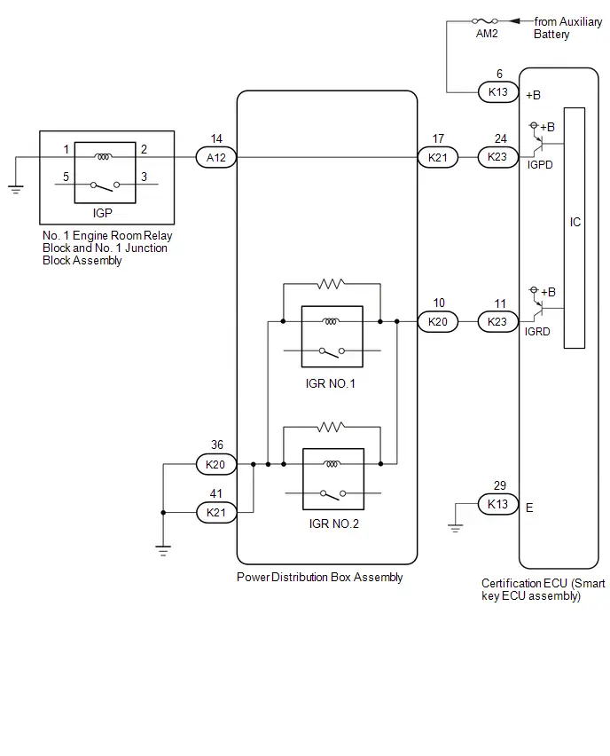
CAUTION / NOTICE / HINT
NOTICE:
-
When using the GTS with the ignition switch off, perform lock and unlock operations using the door control switch of the multiplex network master switch assembly at intervals of 1.5 seconds or less until communication between the GTS and the Toyota Prius vehicle begins, and then select the vehicle model manually.
Then select Model Code "KEY REGIST" under manual mode and enter the following menus: Body Electrical / Smart Key(CAN). While using the GTS, periodically perform lock and unlock operations using the door control switch of the multiplex network master switch assembly at intervals of 1.5 seconds or less to maintain communication between the GTS and the Toyota Prius vehicle.
-
The smart key system (for Start Function) uses the LIN communication system and CAN communication system. Inspect the communication function by following How to Proceed with Troubleshooting. Troubleshoot the smart key system (for Start Function) after confirming that the communication systems are functioning properly.
Click here

-
Before replacing the certification ECU (smart key ECU assembly), refer to Registration.
Click here

- After repair, confirm that no DTCs are output by performing "DTC Output Confirmation Operation".
PROCEDURE
| 1. | CHECK HARNESS AND CONNECTOR (POWER SOURCE) |
Pre-procedure1
(a) Disconnect the K13 certification ECU (smart key ECU assembly) connector.
Procedure1
(b) Measure the voltage according to the value(s) in the table below.
Standard Voltage:
 Click Location & Routing(K13) Click Connector(K13)
 | Tester Connection | Condition | Specified Condition | Result |
|---|---|---|---|
| K13-6 ( B) - Body ground | Ignition switch off | 11 to 14 V | V |
Post-procedure1
(c) None
| NG |

| REPAIR OR REPLACE HARNESS OR CONNECTOR IN CIRCUIT CONNECTED TO POWER SOURCE |
|

| 2. | CHECK HARNESS AND CONNECTOR (GROUND) |
(a) Measure the resistance according to the value(s) in the table below.
Standard Resistance:
 Click Location & Routing(K13) Click Connector(K13)
 | Tester Connection | Condition | Specified Condition | Result |
|---|---|---|---|
| K13-29 (E) - Body ground | Always | Below 1 Ω | Ω |
| NG |

| REPAIR OR REPLACE HARNESS OR CONNECTOR |
|

| 3. | CHECK HARNESS AND CONNECTOR (POWER DISTRIBUTION BOX ASSEMBLY - CERTIFICATION ECU (SMART KEY ECU ASSEMBLY) AND BODY GROUND) |
Pre-procedure1
(a) Disconnect the K23 certification ECU (smart key ECU assembly) connector.
(b) Disconnect the K20 and K21 power distribution box assembly connectors.
Procedure1
(c) Measure the resistance according to the value(s) in the table below.
Standard Resistance:
 Click Location & Routing(K21,K23,K20) Click Connector(K21) Click Connector(K23) Click Connector(K20)
 | Tester Connection | Condition | Specified Condition | Result |
|---|---|---|---|
| K21-17 - K23-24 (IGPD) | Always | Below 1 Ω | Ω |
| K20-10 - K23-11 (IGRD) | Always | Below 1 Ω | Ω |
| K21-17 or K23-24 (IGPD) - Other terminals and body ground | Always | 10 kΩ or higher | kΩ |
| K20-10 or K23-11 (IGRD) - Other terminals and body ground | Always | 10 kΩ or higher | kΩ |
Post-procedure1
(d) None
| NG |

| REPAIR OR REPLACE HARNESS OR CONNECTOR |
|

| 4. | CHECK POWER DISTRIBUTION BOX ASSEMBLY |
Pre-procedure1
(a) Disconnect the A12 power distribution box assembly connector.
Procedure1
(b) Measure the resistance according to the value(s) in the table below.
Standard Resistance:
 Click Location & Routing(K21,A12) Click Connector(K21) Click Connector(A12)
 | Tester Connection | Condition | Specified Condition | Result |
|---|---|---|---|
| K21-17 - A12-14 | Always | Below 1 Ω | Ω |
| K21-17 or A12-14 - Other terminals | Always | 10 kΩ or higher | kΩ |
Post-procedure1
(c) None
| NG |

| REPLACE POWER DISTRIBUTION BOX ASSEMBLY
|


|

| 5. | CHECK HARNESS AND CONNECTOR (POWER DISTRIBUTION BOX ASSEMBLY - IGP RELAY) |
Pre-procedure1
(a) Remove the IGP relay from the No. 1 engine room relay block and No. 1 junction block assembly.
Procedure1
(b) Measure the resistance according to the value(s) in the table below.
Standard Resistance:
 Click Location & Routing(A12) Click Connector(A12)
 | Tester Connection | Condition | Specified Condition | Result |
|---|---|---|---|
| A12-14 - IGP relay terminal 2 | Always | Below 1 Ω | Ω |
| A12-14 or - Other terminals and body ground | Always | 10 kΩ or higher | kΩ |
Post-procedure1
(c) None
| NG |

| REPAIR OR REPLACE HARNESS OR CONNECTOR |
|

| 6. | INSPECT IGP RELAY |
| (a) Measure the resistance according to the value(s) in the table below. Standard Resistance:
Result:
|
|
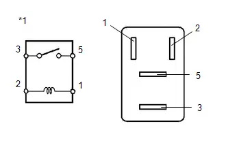
| NG |

| REPLACE IGP RELAY |
|

| 7. | CHECK POWER DISTRIBUTION BOX ASSEMBLY |
(a) Measure the resistance according to the value(s) in the table below.
Standard Resistance:
 Click Location & Routing(K20,K21) Click Connector(K20) Click Connector(K21)
 | Tester Connection | Condition | Specified Condition | Result |
|---|---|---|---|
| K20-10 - K20-36 | Always | 20 Ω or higher | Ω |
| K20-10 - K21-41 | Always | 20 Ω or higher | Ω |
| K20-10 or K20-36 - Other terminals | Always | 10 kΩ or higher | kΩ |
| K20-10 or K21-41 - Other terminals | Always | 10 kΩ or higher | kΩ |
| OK |

| REPLACE CERTIFICATION ECU (SMART KEY ECU ASSEMBLY)
|


| NG |

| REPLACE POWER DISTRIBUTION BOX ASSEMBLY
|


ACC Circuit Short to Ground (B227411)
DESCRIPTION
This DTC is stored when a malfunction in the ACC output circuit is detected. The ACC output circuit is the circuit between terminal ACCD of the certification ECU (smart key ECU assembly) and the ACC relay.
| DTC No. | Detection Item | DTC Detection Condition | Trouble Area | DTC Output from | Priority | Note |
|---|---|---|---|---|---|---|
| B227411 | ACC Circuit Short to Ground | The ACC relay circuit of the certification ECU (smart key ECU assembly) is malfunctioning. (1-trip detection logic*) HINT: When the voltage at terminal ACCD is not at the standard, the system is determined to be malfunctioning. |
| Power Source Control | A | DTC Output Confirmation Operation:
|
- *: Only detected while a malfunction is present.
| Vehicle Condition when Malfunction Detected | Fail-safe Function when Malfunction Detected |
|---|---|
| If there is a malfunction due to the ACC relay being stuck off, the ACC relay does not turn on even though the ignition switch is ACC. HINT: The ignition switch can be turned to ON and the hybrid control system can be started. | - |
| DTC No. | Data List and Active Test |
|---|---|
| B227411 | Power Source Control
|
WIRING DIAGRAM
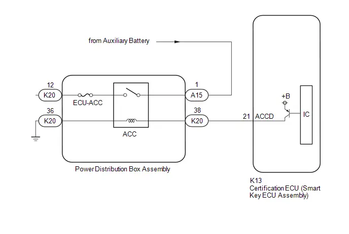
CAUTION / NOTICE / HINT
NOTICE:
-
When using the GTS with the ignition switch off, perform lock and unlock operations using the door control switch of the multiplex network master switch assembly at intervals of 1.5 seconds or less until communication between the GTS and the Toyota Prius vehicle begins, and then select the vehicle model manually.
Then select Model Code "KEY REGIST" under manual mode and enter the following menus: Body Electrical / Smart Key(CAN). While using the GTS, periodically perform lock and unlock operations using the door control switch of the multiplex network master switch assembly at intervals of 1.5 seconds or less to maintain communication between the GTS and the Toyota Prius vehicle.
-
The smart key system (for Start Function) uses the LIN communication system and CAN communication system. Inspect the communication function by following How to Proceed with Troubleshooting. Troubleshoot the smart key system (for Start Function) after confirming that the communication systems are functioning properly.
Click here

- Inspect the fuses for circuits related to this system before performing the following procedure.
-
Before replacing the certification ECU (smart key ECU assembly), refer to Registration.
Click here

- After repair, confirm that no DTCs are output by performing "DTC Output Confirmation Operation".
PROCEDURE
| 1. | CHECK HARNESS AND CONNECTOR (CERTIFICATION ECU (SMART KEY ECU ASSEMBLY) - POWER DISTRIBUTION BOX ASSEMBLY - BODY GROUND) |
Pre-procedure1
(a) Disconnect the K13 certification ECU (smart key ECU assembly) connector.
(b) Disconnect the K20 power distribution box assembly connector.
Procedure1
(c) Measure the resistance according to the value(s) in the table below.
Standard Resistance:
 Click Location & Routing(K13,K20) Click Connector(K13) Click Connector(K20)
 | Tester Connection | Condition | Specified Condition | Result |
|---|---|---|---|
| K13-21 (ACCD) - K20-38 | Always | Below 1 Ω | Ω |
| K20-36 - Body ground | Always | Below 1 Ω | Ω |
| K13-21 (ACCD) or K20-38 - Other terminals and body ground | Always | 10 kΩ or higher | kΩ |
Post-procedure1
(d) None
| NG |

| REPAIR OR REPLACE HARNESS OR CONNECTOR |
|

| 2. | CHECK CERTIFICATION ECU (SMART KEY ECU ASSEMBLY) |
| (a) Measure the voltage according to the value(s) in the table below. Standard Voltage:  Click Location & Routing(K13) Click Connector(K13) Click Location & Routing(K13) Click Connector(K13)
Result:
|
|
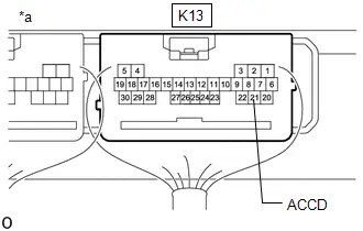
| OK |

| REPLACE POWER DISTRIBUTION BOX ASSEMBLY
|


| NG |

| REPLACE CERTIFICATION ECU (SMART KEY ECU ASSEMBLY)
|


Starter Circuit Short to Ground (B227511,B227512)
DESCRIPTION
This DTC is stored when a malfunction is detected in the starter circuit inside the certification ECU (smart key ECU assembly).
| DTC No. | Detection Item | DTC Detection Condition | Trouble Area | DTC Output from | Priority | Note |
|---|---|---|---|---|---|---|
| B227511 | Starter Circuit Short to Ground | Certification ECU (smart key ECU assembly) internal HV activation request output circuit malfunction or external circuit malfunction (1-trip detection logic*) |
| Power Source Control | B | DTC Output Confirmation Operation:
|
| B227512 | Starter Circuit Short to Battery | Certification ECU (smart key ECU assembly) internal HV activation request output circuit malfunction or external circuit malfunction (1-trip detection logic*) |
| Power Source Control | B | DTC Output Confirmation Operation:
|
- *: Only detected while a malfunction is present and the ignition switch is ON.
| Vehicle Condition when Malfunction Detected | Fail-safe Function when Malfunction Detected |
|---|---|
| - |
| DTC No. | Data List and Active Test |
|---|---|
| B227511 B227512 | - |
WIRING DIAGRAM

CAUTION / NOTICE / HINT
NOTICE:
-
When using the GTS with the ignition switch off, perform lock and unlock operations using the door control switch of the multiplex network master switch assembly at intervals of 1.5 seconds or less until communication between the GTS and the Toyota Prius vehicle begins, and then select the vehicle model manually.
Then select Model Code "KEY REGIST" under manual mode and enter the following menus: Body Electrical / Smart Key(CAN). While using the GTS, periodically perform lock and unlock operations using the door control switch of the multiplex network master switch assembly at intervals of 1.5 seconds or less to maintain communication between the GTS and the Toyota Prius vehicle.
-
The smart key system (for Start Function) uses the LIN communication system and CAN communication system. Inspect the communication function by following How to Proceed with Troubleshooting. Troubleshoot the smart key system (for Start Function) after confirming that the communication systems are functioning properly.
Click here

-
Before replacing the hybrid Toyota Prius vehicle control ECU or certification ECU (smart key ECU assembly), refer to Registration.
Click here

- After repair, confirm that no DTCs are output by performing "DTC Output Confirmation Operation".
PROCEDURE
| 1. | CHECK FOR DTC |
Pre-procedure1
(a) Turn the ignition switch to ON and wait 25 seconds.
Procedure1
(b) Using the GTS, check for certification ECU (smart key ECU assembly) DTCs.
Body Electrical > Power Source Control > Trouble CodesOK:
DTC B228562 is not output simultaneously.
| Result | Proceed to |
|---|---|
| B228562 is not output | A |
| B228562 is output | B |
Post-procedure1
(c) None
| B |

| GO TO DTC B228562 |
|

| 2. | CHECK HARNESS AND CONNECTOR (CERTIFICATION ECU (SMART KEY ECU ASSEMBLY) - HYBRID Toyota Prius Vehicle CONTROL ECU) |
Pre-procedure1
(a) Disconnect the K23 certification ECU (smart key ECU assembly) connector.
(b) Disconnect the K11 hybrid vehicle control ECU connector.
Procedure1
(c) Measure the resistance according to the value(s) in the table below.
Standard Resistance:
 Click Location & Routing(K23,K11) Click Connector(K23) Click Connector(K11)
 | Tester Connection | Condition | Specified Condition | Result |
|---|---|---|---|
| K23-2 (ST2) - K11-11 (ST2) | Always | Below 1 Ω | Ω |
| K23-2 (ST2) or K11-11 (ST2) - Other terminals and body ground | Always | 10 kΩ or higher | kΩ |
Post-procedure1
(d) Connect the K23 certification ECU (smart key ECU assembly) connector.
(e) Connect the K11 hybrid Toyota Prius vehicle control ECU connector.
| NG |

| REPAIR OR REPLACE HARNESS OR CONNECTOR |
|

| 3. | CHECK CERTIFICATION ECU (SMART KEY ECU ASSEMBLY) |
| (a) Measure the voltage according to the value(s) in the table below. Standard Voltage:  Click Location & Routing(K23) Click Connector(K23) Click Location & Routing(K23) Click Connector(K23)
|
|
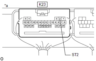
| OK |

| REPLACE HYBRID Toyota Prius Vehicle CONTROL ECU
|


| NG |

| REPLACE CERTIFICATION ECU (SMART KEY ECU ASSEMBLY)
|


Engine/Power Switch Signal Compare Failure (B227862)
DESCRIPTION
This DTC is stored when the SSW1 contact signal, SSW2 contact signal and SSW3 contact signal, which are detected when the power switch is operated, do not match.
| DTC No. | Detection Item | DTC Detection Condition | Trouble Area | DTC Output from | Priority | Note |
|---|---|---|---|---|---|---|
| B227862 | Engine/Power Switch Signal Compare Failure | When the power switch is operated, the SSW1 contact signal, SSW2 contact signal and SSW3 contact signal do not match. |
| Power Source Control | A | DTC Output Confirmation Operation:
|
| Vehicle Condition when Malfunction Detected | Fail-safe Function when Malfunction Detected |
|---|---|
| If there is a malfunction in only one of the terminals SS1, SS2 or SS3, the system can still operate normally. | When only one terminal malfunctions, that terminal is disabled and the system operates normally. |
| DTC No. | Data List and Active Test |
|---|---|
| B227862 | Power Source Control
|
WIRING DIAGRAM
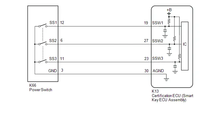
CAUTION / NOTICE / HINT
NOTICE:
-
When using the GTS with the ignition switch off, perform lock and unlock operations using the door control switch of the multiplex network master switch assembly at intervals of 1.5 seconds or less until communication between the GTS and the Toyota Prius vehicle begins, and then select the vehicle model manually.
Then select Model Code "KEY REGIST" under manual mode and enter the following menus: Body Electrical / Smart Key(CAN). While using the GTS, periodically perform lock and unlock operations using the door control switch of the multiplex network master switch assembly at intervals of 1.5 seconds or less to maintain communication between the GTS and the Toyota Prius vehicle.
-
The smart key system (for Start Function) uses the LIN communication system and CAN communication system. Inspect the communication function by following How to Proceed with Troubleshooting. Troubleshoot the smart key system (for Start Function) after confirming that the communication systems are functioning properly.
Click here

-
Before replacing the certification ECU (smart key ECU assembly), refer to Registration.
Click here

- After repair, confirm that no DTCs are output by performing "DTC Output Confirmation Operation".
PROCEDURE
| 1. | READ VALUE USING GTS (PUSH START SWITCH 1) |
(a) Read the Data List according to the display on the GTS.
Body Electrical > Power Source Control > Data List| Tester Display | Measurement Item | Range | Normal Condition | Diagnostic Note |
|---|---|---|---|---|
| Push Start Switch 1 | Power switch 1 status | OFF or ON | OFF: Power switch not pressed |
|
| Tester Display |
|---|
| Push Start Switch 1 |
OK:
The GTS display changes correctly in response to the power switch operation.
| Result | Proceed to |
|---|---|
| The value of Push Start Switch 1 is OFF | A |
| The value of Push Start Switch 1 is not OFF | B |
| B |

| GO TO STEP 13 |
|

| 2. | READ VALUE USING GTS (PUSH START SWITCH 1) |
(a) Read the Data List according to the display on the GTS.
Body Electrical > Power Source Control > Data List| Tester Display | Measurement Item | Range | Normal Condition | Diagnostic Note |
|---|---|---|---|---|
| Push Start Switch 1 | Power switch 1 status | OFF or ON | ON: Power switch pressed |
|
| Tester Display |
|---|
| Push Start Switch 1 |
OK:
The GTS display changes correctly in response to the power switch operation.
| Result | Proceed to |
|---|---|
| The value of Push Start Switch 1 is ON | A |
| The value of Push Start Switch 1 is not ON | B |
| B |

| GO TO STEP 13 |
|

| 3. | READ VALUE USING GTS (PUSH START SWITCH 2) |
(a) Read the Data List according to the display on the GTS.
Body Electrical > Power Source Control > Data List| Tester Display | Measurement Item | Range | Normal Condition | Diagnostic Note |
|---|---|---|---|---|
| Push Start Switch 2 | Power switch 2 status | OFF or ON | OFF: Power switch not pressed |
|
| Tester Display |
|---|
| Push Start Switch 2 |
OK:
The GTS display changes correctly in response to the power switch operation.
| Result | Proceed to |
|---|---|
| The value of Push Start Switch 2 is OFF | A |
| The value of Push Start Switch 2 is not OFF | B |
| B |

| GO TO STEP 13 |
|

| 4. | READ VALUE USING GTS (PUSH START SWITCH 2) |
(a) Read the Data List according to the display on the GTS.
Body Electrical > Power Source Control > Data List| Tester Display | Measurement Item | Range | Normal Condition | Diagnostic Note |
|---|---|---|---|---|
| Push Start Switch 2 | Power switch 2 status | OFF or ON | ON: Power switch pressed |
|
| Tester Display |
|---|
| Push Start Switch 2 |
OK:
The GTS display changes correctly in response to the power switch operation.
| Result | Proceed to |
|---|---|
| The value of Push Start Switch 2 is ON | A |
| The value of Push Start Switch 2 is not ON | B |
| B |

| GO TO STEP 13 |
|

| 5. | READ VALUE USING GTS (PUSH START SWITCH 3) |
(a) Read the Data List according to the display on the GTS.
Body Electrical > Power Source Control > Data List| Tester Display | Measurement Item | Range | Normal Condition | Diagnostic Note |
|---|---|---|---|---|
| Push Start Switch 3 | Power switch 3 status | OFF or ON | OFF: Power switch not pressed |
|
| Tester Display |
|---|
| Push Start Switch 3 |
OK:
The GTS display changes correctly in response to the power switch operation.
| Result | Proceed to |
|---|---|
| The value of Push Start Switch 3 is OFF | A |
| The value of Push Start Switch 3 is not OFF | B |
| B |

| GO TO STEP 13 |
|

| 6. | READ VALUE USING GTS (PUSH START SWITCH 3) |
(a) Read the Data List according to the display on the GTS.
Body Electrical > Power Source Control > Data List| Tester Display | Measurement Item | Range | Normal Condition | Diagnostic Note |
|---|---|---|---|---|
| Push Start Switch 3 | Power switch 3 status | OFF or ON | ON: Power switch pressed |
|
| Tester Display |
|---|
| Push Start Switch 3 |
OK:
The GTS display changes correctly in response to the power switch operation.
| Result | Proceed to |
|---|---|
| The value of Push Start Switch 3 is ON | A |
| The value of Push Start Switch 3 is not ON | B |
| B |

| GO TO STEP 13 |
|

| 7. | READ VALUE USING GTS (PUSH START SWITCH 1) |
(a) According to the display on the GTS, read the Data List while wiggling the wire harness.
Body Electrical > Power Source Control > Data List| Tester Display | Measurement Item | Range | Normal Condition | Diagnostic Note |
|---|---|---|---|---|
| Push Start Switch 1 | Power switch 1 status | OFF or ON | OFF: Power switch not pressed |
|
| Tester Display |
|---|
| Push Start Switch 1 |
OK:
The GTS display changes correctly in response to the power switch operation.
| Result | Proceed to |
|---|---|
| The value of Push Start Switch 1 is OFF | A |
| The value of Push Start Switch 1 is not OFF | B |
| B |

| REPAIR OR REPLACE HARNESS OR CONNECTOR |
|

| 8. | READ VALUE USING GTS (PUSH START SWITCH 1) |
(a) According to the display on the GTS, read the Data List while wiggling the wire harness.
Body Electrical > Power Source Control > Data List| Tester Display | Measurement Item | Range | Normal Condition | Diagnostic Note |
|---|---|---|---|---|
| Push Start Switch 1 | Power switch 1 status | OFF or ON | ON: Power switch pressed |
|
| Tester Display |
|---|
| Push Start Switch 1 |
OK:
The GTS display changes correctly in response to the power switch operation.
| Result | Proceed to |
|---|---|
| The value of Push Start Switch 1 is ON | A |
| The value of Push Start Switch 1 is not ON | B |
| B |

| REPAIR OR REPLACE HARNESS OR CONNECTOR |
|

| 9. | READ VALUE USING GTS (PUSH START SWITCH 2) |
(a) According to the display on the GTS, read the Data List while wiggling the wire harness.
Body Electrical > Power Source Control > Data List| Tester Display | Measurement Item | Range | Normal Condition | Diagnostic Note |
|---|---|---|---|---|
| Push Start Switch 2 | Power switch 2 status | OFF or ON | OFF: Power switch not pressed |
|
| Tester Display |
|---|
| Push Start Switch 2 |
OK:
The GTS display changes correctly in response to the power switch operation.
| Result | Proceed to |
|---|---|
| The value of Push Start Switch 2 is OFF | A |
| The value of Push Start Switch 2 is not OFF | B |
| B |

| REPAIR OR REPLACE HARNESS OR CONNECTOR |
|

| 10. | READ VALUE USING GTS (PUSH START SWITCH 2) |
(a) According to the display on the GTS, read the Data List while wiggling the wire harness.
Body Electrical > Power Source Control > Data List| Tester Display | Measurement Item | Range | Normal Condition | Diagnostic Note |
|---|---|---|---|---|
| Push Start Switch 2 | Power switch 2 status | OFF or ON | ON: Power switch pressed |
|
| Tester Display |
|---|
| Push Start Switch 2 |
OK:
The GTS display changes correctly in response to the power switch operation.
| Result | Proceed to |
|---|---|
| The value of Push Start Switch 2 is ON | A |
| The value of Push Start Switch 2 is not ON | B |
| B |

| REPAIR OR REPLACE HARNESS OR CONNECTOR |
|

| 11. | READ VALUE USING GTS (PUSH START SWITCH 3) |
(a) According to the display on the GTS, read the Data List while wiggling the wire harness.
Body Electrical > Power Source Control > Data List| Tester Display | Measurement Item | Range | Normal Condition | Diagnostic Note |
|---|---|---|---|---|
| Push Start Switch 3 | Power switch 3 status | OFF or ON | OFF: Power switch not pressed |
|
| Tester Display |
|---|
| Push Start Switch 3 |
OK:
The GTS display changes correctly in response to the power switch operation.
| Result | Proceed to |
|---|---|
| The value of Push Start Switch 3 is OFF | A |
| The value of Push Start Switch 3 is not OFF | B |
| B |

| REPAIR OR REPLACE HARNESS OR CONNECTOR |
|

| 12. | READ VALUE USING GTS (PUSH START SWITCH 3) |
(a) According to the display on the GTS, read the Data List while wiggling the wire harness.
Body Electrical > Power Source Control > Data List| Tester Display | Measurement Item | Range | Normal Condition | Diagnostic Note |
|---|---|---|---|---|
| Push Start Switch 3 | Power switch 3 status | OFF or ON | ON: Power switch pressed |
|
| Tester Display |
|---|
| Push Start Switch 3 |
OK:
The GTS display changes correctly in response to the power switch operation.
| Result | Proceed to |
|---|---|
| The value of Push Start Switch 3 is ON | A |
| The value of Push Start Switch 3 is not ON | B |
| A |

| USE SIMULATION METHOD TO CHECK |
| B |

| REPAIR OR REPLACE HARNESS OR CONNECTOR |
| 13. | CHECK HARNESS AND CONNECTOR (CERTIFICATION ECU (SMART KEY ECU ASSEMBLY) - POWER SWITCH) |
Pre-procedure1
(a) Disconnect the K13 certification ECU (smart key ECU assembly) connector.
(b) Disconnect the K66 power switch connector.
Procedure1
(c) Measure the resistance according to the value(s) in the table below.
Standard Resistance:
 Click Location & Routing(K13,K66) Click Connector(K13) Click Connector(K66)
 | Tester Connection | Condition | Specified Condition | Result |
|---|---|---|---|
| K13-19 (SSW1) - K66-12 (SS1) | Always | Below 1 Ω | Ω |
| K13-27 (SSW2) - K66-6 (SS2) | Always | Below 1 Ω | Ω |
| K13-23 (SSW3) - K66-11 (SS3) | Always | Below 1 Ω | Ω |
| K13-30 (AGND) - K66-3 (GND) | Always | Below 1 Ω | Ω |
| K13-19 (SSW1) or K66-12 (SS1) - Other terminals and body ground | Always | 10 kΩ or higher | kΩ |
| K13-27 (SSW2) or K66-6 (SS2) - Other terminals and body ground | Always | 10 kΩ or higher | kΩ |
| K13-23 (SSW3) or K66-11 (SS3) - Other terminals and body ground | Always | 10 kΩ or higher | kΩ |
| K13-30 (AGND) or K66-3 (GND) - Other terminals and body ground | Always | 10 kΩ or higher | kΩ |
Post-procedure1
(d) None
| NG |

| REPAIR OR REPLACE HARNESS OR CONNECTOR |
|

| 14. | INSPECT POWER SWITCH |
Click here

| OK |

| REPLACE CERTIFICATION ECU (SMART KEY ECU ASSEMBLY)
|


| NG |

| REPLACE POWER SWITCH |
Vehicle Speed Signal Circuit Open (B228231,B228262)
DESCRIPTION
DTC B228231 is stored when the vehicle speed signal sent by the skid control ECU via direct line and the vehicle speed signal sent via CAN communication do not match.
DTC B228262 is stored when a malfunction in the vehicle speed sensor is detected.
| DTC No. | Detection Item | DTC Detection Condition | Trouble Area | DTC Output from | Priority | Note |
|---|---|---|---|---|---|---|
| B228231 | Toyota Prius Vehicle Speed Signal Circuit Open | Vehicle speed signal malfunction is detected (excessive deceleration is detected). (1-trip detection logic*) |
| Power Source Control | A | DTC Output Confirmation Operation:
|
| B228262 | Vehicle Speed Signal Compare Failure | The Toyota Prius vehicle speed signal sent by the skid control ECU via direct line and the vehicle speed signal sent via CAN communication do not match. (1-trip detection logic*) |
| Power Source Control | A | DTC Output Confirmation Operation:
|
- *: Only detected while a malfunction is present and the ignition switch is ON.
| DTC Code | Vehicle Condition when Malfunction Detected | Fail-safe Function when Malfunction Detected |
|---|---|---|
| B228231 |
| - |
| B228262 |
| - |
| DTC No. | Data List and Active Test |
|---|---|
| B228231 B228262 | Power Source Control
Brake/EPB
|
WIRING DIAGRAM
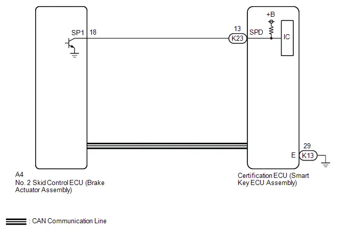
CAUTION / NOTICE / HINT
NOTICE:
-
When using the GTS with the ignition switch off, perform lock and unlock operations using the door control switch of the multiplex network master switch assembly at intervals of 1.5 seconds or less until communication between the GTS and the Toyota Prius vehicle begins, and then select the vehicle model manually.
Then select Model Code "KEY REGIST" under manual mode and enter the following menus: Body Electrical / Smart Key(CAN). While using the GTS, periodically perform lock and unlock operations using the door control switch of the multiplex network master switch assembly at intervals of 1.5 seconds or less to maintain communication between the GTS and the Toyota Prius vehicle.
-
The smart key system (for Start Function) uses the LIN communication system and CAN communication system. Inspect the communication function by following How to Proceed with Troubleshooting. Troubleshoot the smart key system (for Start Function) after confirming that the communication systems are functioning properly.
Click here

-
Before replacing the certification ECU (smart key ECU assembly), refer to Registration.
Click here

- After repair, confirm that no DTCs are output by performing "DTC Output Confirmation Operation".
PROCEDURE
| 1. | READ VALUE USING GTS (Toyota Prius Vehicle SPEED) |
(a) Read the Data List according to the display on the GTS.
Chassis > Brake/EPB > Data List| Tester Display | Measurement Item | Range | Normal Condition | Diagnostic Note |
|---|---|---|---|---|
| Toyota Prius Vehicle Speed | Vehicle speed | Min.: 0.0 km/h (0 mph) Max.: 6553.5 km/h (4072 mph) | Vehicle stopped: 0.0 km/h (0 mph) | When driving at constant speed: No large fluctuations |
| Tester Display |
|---|
| Toyota Prius Vehicle Speed |
OK:
Vehicle speed displayed on the GTS is almost the same as the actual vehicle speed measured using a speedometer tester.
| NG |

| GO TO ELECTRONICALLY CONTROLLED BRAKE SYSTEM
|


|

| 2. | READ VALUE USING GTS (Toyota Prius Vehicle RUNNING CONDITION (LINE)) |
(a) Read the Data List according to the display on the GTS.
Body Electrical > Power Source Control > Data List| Tester Display | Measurement Item | Range | Normal Condition | Diagnostic Note |
|---|---|---|---|---|
| Toyota Prius Vehicle Running Condition (Line) | Vehicle being driven or stopped | Stop or Running | Stop: Vehicle stopped | - |
| Tester Display |
|---|
| Toyota Prius Vehicle Running Condition (Line) |
OK:
The GTS display changes correctly in response to the vehicle condition.
| Result | Proceed to |
|---|---|
| The value of Toyota Prius Vehicle Running Condition (Line) is Stop | A |
| The value of Vehicle Running Condition (Line) is not Stop | B |
| B |

| GO TO STEP 4 |
|

| 3. | READ VALUE USING GTS (Toyota Prius Vehicle RUNNING CONDITION (LINE)) |
(a) Read the Data List according to the display on the GTS.
Body Electrical > Power Source Control > Data List| Tester Display | Measurement Item | Range | Normal Condition | Diagnostic Note |
|---|---|---|---|---|
| Toyota Prius Vehicle Running Condition (Line) | Vehicle being driven or stopped | Stop or Running | Running: Vehicle being driven at 5 km/h (3 mph) or more | - |
| Tester Display |
|---|
| Toyota Prius Vehicle Running Condition (Line) |
OK:
The GTS display changes correctly in response to the vehicle condition.
| Result | Proceed to |
|---|---|
| The value of Toyota Prius Vehicle Running Condition (Line) is Running | A |
| The value of Vehicle Running Condition (Line) is not Running | B |
| A |

| GO TO ELECTRONICALLY CONTROLLED BRAKE SYSTEM
|


|

| 4. | CHECK HARNESS AND CONNECTOR (CERTIFICATION ECU (SMART KEY ECU ASSEMBLY) - NO. 2 SKID CONTROL ECU (BRAKE ACTUATOR ASSEMBLY)) |
Pre-procedure1
(a) Disconnect the A4 No. 2 skid control ECU (brake actuator assembly) connector.
(b) Disconnect the K23 certification ECU (smart key ECU assembly) connector.
Procedure1
(c) Measure the resistance according to the value(s) in the table below.
Standard Resistance:
 Click Location & Routing(K23,A4) Click Connector(K23) Click Connector(A4)
 | Tester Connection | Condition | Specified Condition | Result |
|---|---|---|---|
| K23-13 (SPD) - A4-18 (SP1) | Always | Below 1 Ω | Ω |
| K23-13 (SPD) or A4-18 (SP1) - Other terminals and body ground | Always | 10 kΩ or higher | kΩ |
Post-procedure1
(d) Connect the K23 certification ECU (smart key ECU assembly) connector.
(e) Connect the A4 No. 2 skid control ECU (brake actuator assembly) connector.
| NG |

| REPAIR OR REPLACE HARNESS OR CONNECTOR |
|

| 5. | CHECK CERTIFICATION ECU (SMART KEY ECU ASSEMBLY) |
(a) Using an oscilloscope, check the waveform.
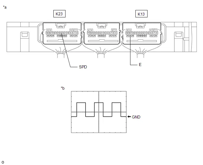
| *a | Component with harness connected (Certification ECU (Smart Key ECU Assembly)) | *b | Waveform |
OK:
 Click Location & Routing(K23,K13) Click Connector(K23) Click Connector(K13)
 | Tester Connection | Condition | Tool Setting | Specified Condition |
|---|---|---|---|
| K23-13 (SPD) - K13-29 (E) | Ignition switch ON, Toyota Prius vehicle being driven at approx. 5 km/h (3 mph) | 5 V/DIV., 20 ms./DIV. | Pulse generation (See waveform) |
HINT:
The wavelength becomes shorter as the vehicle speed increases.
| OK |

| REPLACE CERTIFICATION ECU (SMART KEY ECU ASSEMBLY)
|


| NG |

| GO TO ELECTRONICALLY CONTROLLED BRAKE SYSTEM (HOW TO PROCEED WITH TROUBLESHOOTING)
|


Steering Lock Position Signal Compare Failure (B228562)
DESCRIPTION
This DTC is stored when there is no continuity between terminal SLP of the certification ECU (smart key ECU assembly) and ground.
| DTC No. | Detection Item | DTC Detection Condition | Trouble Area | DTC Output from | Priority | Note |
|---|---|---|---|---|---|---|
| B228562 | Steering Lock Position Signal Compare Failure | This DTC is stored when there is no continuity between terminal SLP of the certification ECU (smart key ECU assembly) and ground. |
| Power Source Control | B | DTC Output Confirmation Operation:
|
| Vehicle Condition when Malfunction Detected | Fail-safe Function when Malfunction Detected |
|---|---|
| The hybrid control system cannot be started. | The ECU does not send a hybrid control system start request. |
| DTC No. | Data List and Active Test |
|---|---|
| B228562 | - |
WIRING DIAGRAM
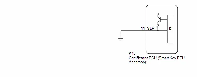
CAUTION / NOTICE / HINT
NOTICE:
-
When using the GTS with the ignition switch off, perform lock and unlock operations using the door control switch of the multiplex network master switch assembly at intervals of 1.5 seconds or less until communication between the GTS and the Toyota Prius vehicle begins, and then select the vehicle model manually.
Then select Model Code "KEY REGIST" under manual mode and enter the following menus: Body Electrical / Smart Key(CAN). While using the GTS, periodically perform lock and unlock operations using the door control switch of the multiplex network master switch assembly at intervals of 1.5 seconds or less to maintain communication between the GTS and the Toyota Prius vehicle.
-
The smart key system (for Start Function) uses the LIN communication system and CAN communication system. Inspect the communication function by following How to Proceed with Troubleshooting. Troubleshoot the smart key system (for Start Function) after confirming that the communication systems are functioning properly.
Click here

- Inspect the fuses for circuits related to this system before performing the following procedure.
-
Before replacing the certification ECU (smart key ECU assembly), refer to Registration.
Click here

- After repair, confirm that no DTCs are output by performing "DTC Output Confirmation Operation".
PROCEDURE
| 1. | CHECK FOR DTC |
(a) Check for DTCs.
Body Electrical > Smart Key > Trouble Codes| Result | Proceed to |
|---|---|
| B278588 is not output | A |
| B278588 is output | B |
| B |

| GO TO DTC B278588 |
|

| 2. | CHECK HARNESS AND CONNECTOR (CERTIFICATION ECU (SMART KEY ECU ASSEMBLY) - BODY GROUND) |
Pre-procedure1
(a) Disconnect the K13 certification ECU (smart key ECU assembly) connector.
Procedure1
(b) Measure the resistance according to the value(s) in the table below.
Standard Resistance:
 Click Location & Routing(K13) Click Connector(K13)
 | Tester Connection | Condition | Specified Condition | Result |
|---|---|---|---|
| K13-11 (SLP) - Body ground | Always | Below 1 Ω | Ω |
Post-procedure1
(c) None
| OK |

| REPLACE CERTIFICATION ECU (SMART KEY ECU ASSEMBLY)
|


| NG |

| REPAIR OR REPLACE HARNESS OR CONNECTOR |
Battery Circuit or Ground Circuit Energization Malfunction (B228B00)
DESCRIPTION
This DTC is stored when there is a malfunction in the certification ECU (smart key ECU assembly) auxiliary battery power supply circuit or ground circuit.
| DTC No. | Detection Item | DTC Detection Condition | Trouble Area | DTC Output from | Priority | Note |
|---|---|---|---|---|---|---|
| B228B00 | Battery Circuit or Ground Circuit Energization Malfunction | A malfunction is detected in the certification ECU (smart key ECU assembly) auxiliary battery power supply circuit or ground circuit. (1-trip detection logic*) |
| Power Source Control | A | DTC Output Confirmation Operation:
|
- *: Only detected while a malfunction is present.
| Vehicle Condition when Malfunction Detected | Fail-safe Function when Malfunction Detected |
|---|---|
| The hybrid control system stopped while driving. | - |
| DTC No. | Data List and Active Test |
|---|---|
| B228B00 | - |
WIRING DIAGRAM
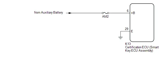
CAUTION / NOTICE / HINT
NOTICE:
-
When using the GTS with the ignition switch off, perform lock and unlock operations using the door control switch of the multiplex network master switch assembly at intervals of 1.5 seconds or less until communication between the GTS and the Toyota Prius vehicle begins, and then select the vehicle model manually.
Then select Model Code "KEY REGIST" under manual mode and enter the following menus: Body Electrical / Smart Key(CAN). While using the GTS, periodically perform lock and unlock operations using the door control switch of the multiplex network master switch assembly at intervals of 1.5 seconds or less to maintain communication between the GTS and the Toyota Prius vehicle.
-
The smart key system (for Start Function) uses the LIN communication system and CAN communication system. Inspect the communication function by following How to Proceed with Troubleshooting. Troubleshoot the smart key system (for Start Function) after confirming that the communication systems are functioning properly.
Click here

- Inspect the fuses for circuits related to this system before performing the following procedure.
- After repair, confirm that no DTCs are output by performing "DTC Output Confirmation Operation".
PROCEDURE
| 1. | CHECK HARNESS AND CONNECTOR (POWER SOURCE) |
Pre-procedure1
(a) Disconnect the K13 certification ECU (smart key ECU assembly) connector.
Procedure1
(b) Measure the voltage according to the value(s) in the table below.
Standard Voltage:
 Click Location & Routing(K13) Click Connector(K13)
 | Tester Connection | Condition | Specified Condition | Result |
|---|---|---|---|
| K13-6 ( B) - Body ground | Ignition switch off | 11 to 14 V | V |
Post-procedure1
(c) None
| NG |

| REPAIR OR REPLACE HARNESS OR CONNECTOR IN CIRCUIT CONNECTED TO POWER SOURCE |
|

| 2. | CHECK HARNESS AND CONNECTOR (GROUND) |
(a) Measure the resistance according to the value(s) in the table below.
Standard Resistance:
 Click Location & Routing(K13) Click Connector(K13)
 | Tester Connection | Condition | Specified Condition | Result |
|---|---|---|---|
| K13-29 (E) - Body ground | Always | Below 1 Ω | Ω |
| OK |

| END (TEMPORARY CONNECTION FAILURE IS SUSPECTED) |
| NG |

| REPAIR OR REPLACE HARNESS OR CONNECTOR IN CIRCUIT CONNECTED TO POWER SOURCE |
Wireless Starter Component Internal Failure (B277A96)
DESCRIPTION
If the remote engine start ECU*1 or DCM (telematics transceiver)*2 does not respond to the certification ECU (smart key ECU assembly) or the remote engine start ID is not registered, this DTC is stored.
HINT:
Registration status of the DCM (telematics transceiver) can be checked using the "Remote Engine Starter Registration Status" item in the Data List.*2
- *1: w/ Genuine Remote Engine Start
- *2: for Remote Connect Compatible Type
| DTC No. | Detection Item | DTC Detection Condition | Trouble Area | DTC Output from | Priority | Note |
|---|---|---|---|---|---|---|
| B277A96 | Wireless Starter Component Internal Failure | One of the following conditions is met (1 trip detection logic*3):
|
| Smart Key | B | DTC output confirmation operation:
|
- *1: w/ Genuine Remote Engine Start
- *2: for Remote Connect Compatible Type
- *3: Only output while a malfunction is present.
| Vehicle Condition when Malfunction Detected | Fail-safe Operation when Malfunction Detected |
|---|---|
| Hybrid control system does not start with remote start operation | Hybrid control system cannot be started by remote start operation only |
| DTC No. | Data List and Active Test |
|---|---|
| B277A96 | Telematics
|
- *: for Remote Connect Compatible Type
CAUTION / NOTICE / HINT
NOTICE:
-
When using the GTS with the ignition switch off, perform lock and unlock operations using the door control switch of the multiplex network master switch assembly at intervals of 1.5 seconds or less until communication between the GTS and the Toyota Prius vehicle begins, and then select the vehicle model manually.
Then select Model Code "KEY REGIST" under manual mode and enter the following menus: Body Electrical / Smart Key(CAN). While using the GTS, periodically perform lock and unlock operations using the door control switch of the multiplex network master switch assembly at intervals of 1.5 seconds or less to maintain communication between the GTS and the Toyota Prius vehicle.
-
The smart key system (for Start Function) uses the LIN communication system and CAN communication system. Inspect the communication function by following How to Proceed with Troubleshooting. Troubleshoot the smart key system (for Start Function) after confirming that the communication systems are functioning properly.
Click here

-
Before replacing the certification ECU (smart key ECU assembly), refer to Registration.*
Click here

- *: w/ Genuine Remote Engine Start
- After performing repairs, confirm that no DTCs are output by performing "DTC Output Confirmation Operation".
PROCEDURE
| 1. | CHECK CAN COMMUNICATION SYSTEM |
(a) Check for CAN communication system DTCs.
HINT:
for PHEV Model: Click here

for HEV Model: Click here

OK:
CAN communication DTCs are not output.
| NG |

| GO TO CAN COMMUNICATION SYSTEM (DIAGNOSTIC TROUBLE CODE CHART) for PHEV Model: Click here
for HEV Model: Click here
|


|

| 2. | CONFIRM MODEL |
(a) Choose the model to be inspected.
| Result | Proceed to |
|---|---|
| w/ Genuine Remote Engine Start | A |
| for Remote Connect Compatible Type | B |
| B |

| GO TO TELEMATICS SYSTEM (Remote Engine Starter does not Operate) |
|

| 3. | REGISTER REMOTE ENGINE STARTER ID |
(a) Register the remote engine starter ID.
OK:
Registration can be completed.
| NG |

| REPLACE CERTIFICATION ECU (SMART KEY ECU ASSEMBLY) |
|

| 4. | CHECK REMOTE ENGINE STARTER FUNCTION |
(a) Check the remote engine starter function.
OK:
Remote engine starter functions operate normally.
| OK |

| END (REMOTE ENGINE STARTER ID WAS NOT REGISTERED) |
| NG |

| REPLACE REMOTE ENGINE START ECU |
Steering Lock System Component Internal Failure (B278196,B278211,B278215,B279F1C)
DESCRIPTION
As this DTC is not normally output, it may be due to noise in the LIN communication system, etc.
| DTC No. | Detection Item | DTC Detection Condition | Trouble Area | DTC Output from | Priority | Note |
|---|---|---|---|---|---|---|
| B278196 | Steering Lock System Component Internal Failure | Noise in the LIN communication system, etc. | ID code box (immobiliser code ECU) | Smart Key | A | DTC Output Confirmation Operation:
|
| B278211 | Power Source Control System Circuit Short to Ground | Noise in the LIN communication system, etc. | ID code box (immobiliser code ECU) | Smart Key | A | DTC Output Confirmation Operation:
|
| B278215 | Power Source Control System Circuit Short to Battery or Open | Noise in the LIN communication system, etc. | ID code box (immobiliser code ECU) | Smart Key | A | DTC Output Confirmation Operation:
|
| B279F1C | Steering Lock Confirmation Signal Circuit Voltage Out of Range | Noise in the LIN communication system, etc. | ID code box (immobiliser code ECU) | Smart Key | A | DTC Output Confirmation Operation:
|
| DTC Code | Vehicle Condition when Malfunction Detected | Fail-safe Function when Malfunction Detected |
|---|---|---|
| B278196 | The hybrid control system cannot be started. | - |
| B278211 | ||
| B278215 | ||
| B279F1C |
| DTC No. | Data List and Active Test |
|---|---|
| B278196 B278211 B278215 B279F1C | - |
CAUTION / NOTICE / HINT
NOTICE:
-
When using the GTS with the ignition switch off, perform lock and unlock operations using the door control switch of the multiplex network master switch assembly at intervals of 1.5 seconds or less until communication between the GTS and the Toyota Prius vehicle begins, and then select the vehicle model manually.
Then select Model Code "KEY REGIST" under manual mode and enter the following menus: Body Electrical / Smart Key(CAN). While using the GTS, periodically perform lock and unlock operations using the door control switch of the multiplex network master switch assembly at intervals of 1.5 seconds or less to maintain communication between the GTS and the Toyota Prius vehicle.
-
The smart key system (for Start Function) uses the LIN communication system and CAN communication system. Inspect the communication function by following How to Proceed with Troubleshooting. Troubleshoot the smart key system (for Start Function) after confirming that the communication systems are functioning properly.
Click here

-
Before replacing the ID code box (immobiliser code ECU), refer to Registration.
Click here

- After performing repairs, confirm that no DTCs are output again.
HINT:
When all the ECUs that are connected via LIN communication cannot communicate with the certification ECU (smart key ECU assembly), DTC B278588 is stored.
PROCEDURE
| 1. | CLEAR DTC |
(a) Clear the DTCs.
Body Electrical > Smart Key > Clear DTCs
|

| 2. | CHECK FOR DTC |
(a) Check for DTCs.
Body Electrical > Smart Key > Trouble Codes| Result | Proceed to |
|---|---|
| B278196, B278211, B278215 or B279F1C is output | A |
| B278196, B278211, B278215 and B279F1C are not output | B |
| A |

| REPLACE ID CODE BOX (IMMOBILISER CODE ECU)
|


| B |

| END |
Antenna Coil Circuit Voltage Out of Range (B27841C)
DESCRIPTION
When an open or short circuit is detected in the transponder key amplifier coil built into the power switch, the certification ECU (smart key ECU assembly) stores this DTC. This DTC is also stored as a history DTC.
| DTC No. | Detection Item | DTC Detection Condition | Trouble Area | DTC Output from | Priority | Note |
|---|---|---|---|---|---|---|
| B27841C | Antenna Coil Circuit Voltage Out of Range | The transponder key amplifier coil built into the power switch is open (see below) or shorted (determined by communication with certification ECU (smart key ECU assembly)). (1 trip detection logic*) |
| Smart Key | A | DTC output confirmation operation:
|
- *: Only output while a malfunction is present.
| Vehicle Condition when Malfunction Detected | Fail-safe Operation when Malfunction Detected |
|---|---|
| Hybrid control system cannot be started when transmitter battery is depleted by holding electrical key transmitter sub-assembly near power switch and pressing and holding power switch with shift position in P | - |
| DTC No. | Data List and Active Test |
|---|---|
| B27841C | - |
WIRING DIAGRAM

CAUTION / NOTICE / HINT
NOTICE:
-
When using the GTS with the ignition switch off, perform lock and unlock operations using the door control switch of the multiplex network master switch assembly at intervals of 1.5 seconds or less until communication between the GTS and the Toyota Prius vehicle begins, and then select the vehicle model manually.
Then select Model Code "KEY REGIST" under manual mode and enter the following menus: Body Electrical / Smart Key(CAN). While using the GTS, periodically perform lock and unlock operations using the door control switch of the multiplex network master switch assembly at intervals of 1.5 seconds or less to maintain communication between the GTS and the Toyota Prius vehicle.
-
The smart key system (for Start Function) uses the LIN communication system and CAN communication system. Inspect the communication function by following How to Proceed with Troubleshooting. Troubleshoot the smart key system (for Start Function) after confirming that the communication systems are functioning properly.
Click here

-
Before replacing the certification ECU (smart key ECU assembly), refer to Registration.
Click here

- After performing repairs, confirm that no DTCs are output by performing "DTC Output Confirmation Operation".
PROCEDURE
| 1. | CHECK CONNECTION OF CONNECTOR |
(a) Check that the connectors are properly connected to the power switch and certification ECU (smart key ECU assembly).
OK:
Connectors are properly connected.
| NG |

| CONNECT CONNECTORS PROPERLY |
|

| 2. | CHECK HARNESS AND CONNECTOR (CERTIFICATION ECU (SMART KEY ECU ASSEMBLY) - POWER SWITCH AND BODY GROUND) |
Pre-procedure1
(a) Disconnect the K13 certification ECU (smart key ECU assembly) connector.
(b) Disconnect the K66 power switch connector.
Procedure1
(c) Measure the resistance according to the value(s) in the table below.
Standard Resistance:
 Click Location & Routing(K13,K66) Click Connector(K13) Click Connector(K66)
 | Tester Connection | Condition | Specified Condition | Result |
|---|---|---|---|
| K13-12 (ANT1) - K66-1 (ANT1) | Always | Below 1 Ω | Ω |
| K13-12 (ANT1) or K66-1 (ANT1) - Other terminals and body ground | Always | 10 kΩ or higher | kΩ |
| K13-13 (ANT2) - K66-7 (ANT2) | Always | Below 1 Ω | Ω |
| K13-13 (ANT2) or K66-7 (ANT2) - Other terminals and body ground | Always | 10 kΩ or higher | kΩ |
Post-procedure1
(d) Connect the K13 certification ECU (smart key ECU assembly) connector.
| NG |

| REPAIR OR REPLACE HARNESS OR CONNECTOR |
|

| 3. | CHECK CERTIFICATION ECU (SMART KEY ECU ASSEMBLY) |
(a) Using an oscilloscope, check the waveform.

| *a | Component with harness connected (Certification ECU (Smart Key ECU Assembly)) | *b | Waveform 1 |
| *c | Waveform 2 | - | - |
OK:
 Click Location & Routing(K13) Click Connector(K13)
 | Tester Connection | Condition | Tool Setting | Specified Condition |
|---|---|---|---|
| K13-12 (ANT1) - K13-29 (E) | Ignition switch off, electrical key transmitter sub-assembly not in cabin, within 30 seconds of power switch pressed | 5 V/DIV., 200 ms./DIV. | Pulse generation (See waveform 1) |
| K13-13 (ANT2) - K13-29 (E) | Ignition switch off, electrical key transmitter sub-assembly not in cabin, within 30 seconds of power switch pressed | 20 V/DIV., 200 ms./DIV. | Pulse generation (See waveform 2) |
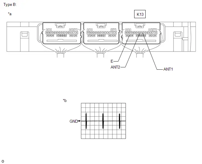
| *a | Component with harness connected (Certification ECU (Smart Key ECU Assembly)) | *b | Waveform 1 |
OK:
 Click Location & Routing(K13) Click Connector(K13)
 | Tester Connection | Condition | Tool Setting | Specified Condition |
|---|---|---|---|
| K13-12 (ANT1) - K13-29 (E) | Ignition switch off, electrical key transmitter sub-assembly not in cabin, within 30 seconds of power switch pressed | 20 V/DIV., 200 ms./DIV. | Pulse generation (See waveform 1) |
| K13-13 (ANT2) - K13-29 (E) | Ignition switch off, electrical key transmitter sub-assembly not in cabin, within 30 seconds of power switch pressed | 20 V/DIV., 200 ms./DIV. | Pulse generation (See waveform 1) |
| OK |

| REPLACE POWER SWITCH |
| NG |

| REPLACE CERTIFICATION ECU (SMART KEY ECU ASSEMBLY)
|


ID-BOX Component Internal Failure (B278D96)
DESCRIPTION
When the certification ECU (smart key ECU assembly) detects an input signal indicating that the vehicle is equipped with an ID code box even though the ID code box is not registered, the certification ECU (smart key ECU assembly) stores this DTC.
| DTC No. | Detection Item | DTC Detection Condition | Trouble Area | DTC Output from | Priority | Note |
|---|---|---|---|---|---|---|
| B278D96 | ID-BOX Component Internal Failure | One of the following conditions is met:
| Misconnection of the ID code box | Smart Key | A | DTC output confirmation operation:
|
| Vehicle Condition when Malfunction Detected | Fail-safe Operation when Malfunction Detected |
|---|---|
| Key registration will be prohibited | - |
| DTC No. | Data List and Active Test |
|---|---|
| B278D96 | - |
CAUTION / NOTICE / HINT
NOTICE:
-
When using the GTS with the ignition switch off, perform lock and unlock operations using the door control switch of the multiplex network master switch assembly at intervals of 1.5 seconds or less until communication between the GTS and the Toyota Prius vehicle begins, and then select the vehicle model manually.
Then select Model Code "KEY REGIST" under manual mode and enter the following menus: Body Electrical / Smart Key(CAN). While using the GTS, periodically perform lock and unlock operations using the door control switch of the multiplex network master switch assembly at intervals of 1.5 seconds or less to maintain communication between the GTS and the Toyota Prius vehicle.
-
The smart key system (for Start Function) uses the LIN communication system and CAN communication system. Inspect the communication function by following How to Proceed with Troubleshooting. Troubleshoot the smart key system (for Start Function) after confirming that the communication systems are functioning properly.
Click here

-
Before replacing the certification ECU (smart key ECU assembly), refer to Registration.
Click here

- After repair, confirm that no DTCs are output by performing "DTC Output Confirmation Operation."
PROCEDURE
| 1. | CLEAR DTC |
(a) Clear the DTCs.
Body Electrical > Smart Key > Clear DTCs
|

| 2. | CHECK DTC OUTPUT |
(a) Check for DTCs.
Body Electrical > Smart Key > Trouble CodesHINT:
Before checking for DTCs, perform the "DTC Output Confirmation Operation" procedure.
| Result | Proceed to |
|---|---|
| B278D96 is not output | A |
| B278D96 is output | B |
| A |

| END |
| B |

| REPLACE CERTIFICATION ECU (SMART KEY ECU ASSEMBLY)
|


Immobiliser Amp Missing Message (B278E87)
DESCRIPTION
A transponder key amplifier is built into the certification ECU (smart key ECU assembly).
When a communication malfunction occurs with the transponder key amplifier inside the certification ECU (smart key ECU assembly), this DTC is stored.
| DTC No. | Detection Item | DTC Detection Condition | Trouble Area | DTC Output from | Priority | Note |
|---|---|---|---|---|---|---|
| B278E87 | Immobiliser Amp Missing Message | A communication malfunction with the transponder key amplifier inside the certification ECU (smart key ECU assembly) is detected. (1-trip detection logic*). | Certification ECU (smart key ECU assembly) | Smart Key | A | DTC Output Confirmation Operation:
|
- *: Only detected while a malfunction is present and the ignition switch is ON.
| Vehicle Condition when Malfunction Detected | Fail-safe Function when Malfunction Detected |
|---|---|
| Hybrid control system cannot be started when transmitter battery is depleted by holding electrical key transmitter sub-assembly near power switch and pressing and holding power switch with shift position in P | - |
| DTC No. | Data List and Active Test |
|---|---|
| B278E87 | - |
CAUTION / NOTICE / HINT
NOTICE:
-
When using the GTS with the ignition switch off, perform lock and unlock operations using the door control switch of the multiplex network master switch assembly at intervals of 1.5 seconds or less until communication between the GTS and the Toyota Prius vehicle begins, and then select the vehicle model manually.
Then select Model Code "KEY REGIST" under manual mode and enter the following menus: Body Electrical / Smart Key(CAN). While using the GTS, periodically perform lock and unlock operations using the door control switch of the multiplex network master switch assembly at intervals of 1.5 seconds or less to maintain communication between the GTS and the Toyota Prius vehicle.
-
The smart key system (for Start Function) uses the LIN communication system and CAN communication system. Inspect the communication function by following How to Proceed with Troubleshooting. Troubleshoot the smart key system (for Start Function) after confirming that the communication systems are functioning properly.
Click here

-
Before replacing the certification ECU (smart key ECU assembly), refer to Registration.
Click here

- After performing repairs, confirm that no DTCs are output again.
PROCEDURE
| 1. | CLEAR DTC |
(a) Clear the DTCs.
Body Electrical > Smart Key > Clear DTCs
|

| 2. | CHECK FOR DTC |
(a) Press the power switch with the electric key transmitter sub-assembly not in the cabin.
(b) Check for DTCs.
Body Electrical > Smart Key > Trouble Codes| Result | Proceed to |
|---|---|
| B278E87 is output | A |
| B278E87 is not output | B |
| A |

| REPLACE CERTIFICATION ECU (SMART KEY ECU ASSEMBLY)
|


| B |

| USE SIMULATION METHOD TO CHECK |
ID-BOX Calibration / Parameter Memory Failure (B279046)
DESCRIPTION
When an internal malfunction occurs in the ID code box (immobiliser code ECU), the certification ECU (smart key ECU assembly) stores this DTC.
| DTC No. | Detection Item | DTC Detection Condition | Trouble Area | DTC Output from | Priority | Note |
|---|---|---|---|---|---|---|
| B279046 | ID-BOX Calibration / Parameter Memory Failure | An internal malfunction occurs in the ID code box (immobiliser code ECU) (EEPROM access malfunction) (1 trip detection logic*). |
| Smart Key | A | DTC output confirmation operation:
|
- *: Only output while a malfunction is present.
| Vehicle Condition when Malfunction Detected | Fail-safe Operation when Malfunction Detected |
|---|---|
| - |
| DTC No. | Data List and Active Test |
|---|---|
| B279046 | - |
CAUTION / NOTICE / HINT
NOTICE:
-
When using the GTS with the ignition switch off, perform lock and unlock operations using the door control switch of the multiplex network master switch assembly at intervals of 1.5 seconds or less until communication between the GTS and the Toyota Prius vehicle begins, and then select the vehicle model manually.
Then select Model Code "KEY REGIST" under manual mode and enter the following menus: Body Electrical / Smart Key(CAN). While using the GTS, periodically perform lock and unlock operations using the door control switch of the multiplex network master switch assembly at intervals of 1.5 seconds or less to maintain communication between the GTS and the Toyota Prius vehicle.
-
The smart key system (for Start Function) uses the LIN communication system and CAN communication system. Inspect the communication function by following How to Proceed with Troubleshooting. Troubleshoot the smart key system (for Start Function) after confirming that the communication systems are functioning properly.
Click here

-
Before replacing the ID code box (immobiliser code ECU), refer to Registration.
Click here

- After performing repairs, confirm that no DTCs are output by performing "DTC Output Confirmation Operation."
PROCEDURE
| 1. | REPLACE ID CODE BOX (IMMOBILISER CODE ECU) |
(a) Replace the ID code box (immobiliser code ECU) with a new one.
HINT:
Click here


|

| 2. | CLEAR DTC |
(a) Using the GTS, clear the DTCs.
Body Electrical > Smart Key > Clear DTCs
|

| 3. | REGISTER RECOGNITION CODE |
(a) Register the recognition codes to the ECUs.
HINT:
Click here

|

| 4. | REGISTER ECU COMMUNICATION ID |
(a) Register the ECU communication ID codes.
HINT:
Click here

|

| 5. | CHECK DTC |
(a) Using the GTS, check if DTC is output.
Body Electrical > Smart Key > Trouble Codes| Result | Proceed to |
|---|---|
| B279046 is output | A |
| B279046 is not output | B |
| A |

| REPLACE CERTIFICATION ECU (SMART KEY ECU ASSEMBLY)
|


| B |

| END (ID CODE BOX (IMMOBILISER CODE ECU) WAS DEFECTIVE) |
Engine Immobiliser System Signal (Some Circuit Quantity, Reported via Serial Data) Invalid (B279986)
DESCRIPTION
If there is a communication malfunction between the hybrid vehicle control ECU and ID code box (immobiliser code ECU), or when the communication ID codes do not match, the hybrid vehicle control ECU stores this DTC.
| DTC No. | Detection Item | DTC Detection Condition | Trouble Area | DTC Output from | Priority | Note |
|---|---|---|---|---|---|---|
| B279986 | Engine Immobiliser System Signal (Some Circuit Quantity, Reported via Serial Data) Invalid | Either of the following conditions is met (1 trip detection logic*):
|
| Hybrid Control | A | DTC output confirmation operation (Perform either of the following):
|
- *: Only output while a malfunction is present.
| Vehicle Condition when Malfunction Detected | Fail-safe Operation when Malfunction Detected |
|---|---|
| Hybrid control system cannot be started | - |
| DTC No. | Data List and Active Test |
|---|---|
| B279986 | - |
WIRING DIAGRAM
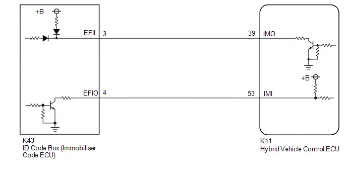
CAUTION / NOTICE / HINT
NOTICE:
-
When using the GTS with the ignition switch off, perform lock and unlock operations using the door control switch of the multiplex network master switch assembly at intervals of 1.5 seconds or less until communication between the GTS and the Toyota Prius vehicle begins, and then select the vehicle model manually.
Then select Model Code "KEY REGIST" under manual mode and enter the following menus: Body Electrical / Smart Key(CAN). While using the GTS, periodically perform lock and unlock operations using the door control switch of the multiplex network master switch assembly at intervals of 1.5 seconds or less to maintain communication between the GTS and the Toyota Prius vehicle.
-
The smart key system (for Start Function) uses the LIN communication system and CAN communication system. Inspect the communication function by following How to Proceed with Troubleshooting. Troubleshoot the smart key system (for Start Function) after confirming that the communication systems are functioning properly.
Click here

-
Before replacing the hybrid Toyota Prius vehicle control ECU or ID code box (immobiliser code ECU), refer to Registration.
Click here

- After performing repairs, confirm that no DTCs are output by performing "DTC Output Confirmation Operation".
-
When the hybrid vehicle control ECU is replaced, update the ECU security key.
Click here

HINT:
When DTC B279986 and the certification ECU (smart key ECU assembly) DTC are output simultaneously, first perform troubleshooting for the certification ECU (smart key ECU assembly) DTC.
PROCEDURE
| 1. | REGISTER ECU COMMUNICATION ID |
(a) Register the ECU communication ID code.
HINT:
Click here

|

| 2. | CHECK HYBRID Toyota Prius Vehicle CONTROL ECU (TERMINAL IMO) |
(a) Using an oscilloscope, check the waveform.
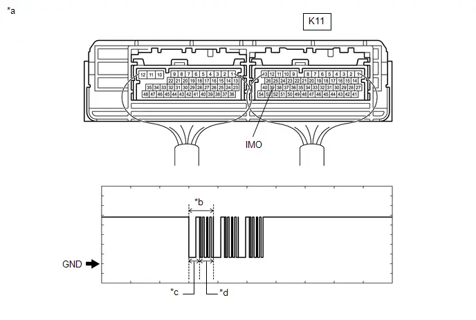
| *a | Component with harness connected (Hybrid Toyota Prius Vehicle Control ECU) | *b | Waveform |
| *c | Approximately 160 ms. | *d | Approximately 270 ms. |
OK:
 Click Location & Routing(K11) Click Connector(K11)
 | Tester Connection | Condition | Tool Setting | Specified Condition |
|---|---|---|---|
| K11-39 (IMO) - Body ground | Within 3 seconds of hybrid control system start or within 3 seconds of ignition switch turned to ON after cable disconnected and reconnected to auxiliary battery | 2 V/DIV., 500 ms./DIV. | Pulse generation (See waveform) |
| Result | Proceed to |
|---|---|
| Normal waveform | A |
| Terminal IMO stuck low (2.4 V or less) | B |
| Waveform not output, has abnormal wavelength or shape or Terminal IMO stuck high (12V) | C |
| B |

| GO TO STEP 7 |
| C |

| GO TO STEP 9 |
|

| 3. | CHECK HYBRID Toyota Prius Vehicle CONTROL ECU (TERMINAL IMI) |
(a) Using an oscilloscope, check the waveform.
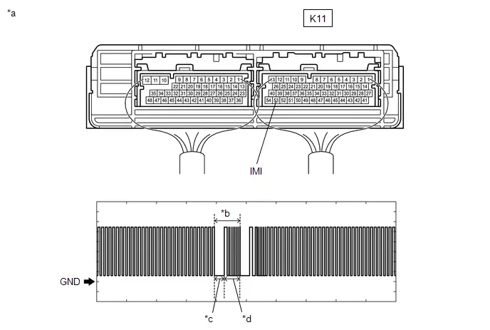
| *a | Component with harness connected (Hybrid Toyota Prius Vehicle Control ECU) | *b | Waveform |
| *c | Approximately 160 ms. | *d | Approximately 270 ms. |
OK:
 Click Location & Routing(K11) Click Connector(K11)
 | Tester Connection | Condition | Tool Setting | Specified Condition |
|---|---|---|---|
| K11-53 (IMI) - Body ground | Within 3 seconds of hybrid control system start or within 3 seconds of ignition switch turned to ON after cable disconnected and reconnected to auxiliary battery | 2 V/DIV., 500 ms./DIV. | Pulse generation (See waveform) |
| NG |

| GO TO STEP 6 |
|

| 4. | REGISTER ECU COMMUNICATION ID |
(a) Register the ECU communication ID code.
HINT:
Click here

|

| 5. | CHECK WHETHER HYBRID CONTROL SYSTEM STARTS |
Pre-procedure1
(a) Using an electrical key transmitter sub-assembly which is registered to the Toyota Prius vehicle, turn the ignition switch to ON.
Procedure1
(b) Check that the hybrid control system starts 5 seconds after the ignition switch turned to ON.
OK:
Hybrid control system starts normally.
Post-procedure1
(c) None
| OK |

| END (ECU COMMUNICATION ID HAS NOT BEEN REGISTERED) |
| NG |

| REPLACE HYBRID Toyota Prius Vehicle CONTROL ECU
|


| 6. | CHECK HARNESS AND CONNECTOR (ID CODE BOX (IMMOBILISER CODE ECU) - HYBRID Toyota Prius Vehicle CONTROL ECU) |
Pre-procedure1
(a) Disconnect the K43 ID code box (immobiliser code ECU) connector.
(b) Disconnect the K11 hybrid vehicle control ECU connector.
Procedure1
(c) Measure the resistance according to the value(s) in the table below.
Standard Resistance:
 Click Location & Routing(K43,K11) Click Connector(K43) Click Connector(K11)
 | Tester Connection | Condition | Specified Condition | Result |
|---|---|---|---|
| K43-4 (EFIO) - K11-53 (IMI) | Always | Below 1 Ω | Ω |
| K43-4 (EFIO) or K11-53 (IMI) - Other terminals and body ground | Always | 10 kΩ or higher | kΩ |
Post-procedure1
(d) None
| OK |

| REPLACE ID CODE BOX (IMMOBILISER CODE ECU)
|


| NG |

| REPAIR OR REPLACE HARNESS OR CONNECTOR |
| 7. | CHECK HYBRID Toyota Prius Vehicle CONTROL ECU |
Pre-procedure1
(a) Disconnect the K11 hybrid vehicle control ECU connector.
Procedure1
(b) Measure the voltage according to the value(s) in the table below.
Standard Voltage:
 Click Location & Routing(K11) Click Connector(K11)
 | Tester Connection | Condition | Specified Condition |
|---|---|---|
| K11-39 (IMO) - Body ground | Ignition switch turned to ON using registered electrical key transmitter sub-assembly | Terminal IMO stuck low (2.4 V or less) |
| Terminal IMO stuck high (12 V) or abnormal waveform |
| Result | Proceed to |
|---|---|
| Terminal IMO stuck low (2.4 V or less) | A |
| Terminal IMO stuck high (12 V) or abnormal waveform | B |
Post-procedure1
(c) None
| B |

| REPLACE HYBRID Toyota Prius Vehicle CONTROL ECU
|


|

| 8. | CHECK HARNESS AND CONNECTOR (ID CODE BOX (IMMOBILISER CODE ECU) - HYBRID Toyota Prius Vehicle CONTROL ECU) |
Pre-procedure1
(a) Disconnect the K43 ID code box (immobiliser code ECU) connector.
Procedure1
(b) Measure the resistance according to the value(s) in the table below.
Standard Resistance:
 Click Location & Routing(K43,K11) Click Connector(K43) Click Connector(K11)
 | Tester Connection | Condition | Specified Condition | Result |
|---|---|---|---|
| K43-3 (EFII) - K11-39 (IMO) | Always | Below 1 Ω | Ω |
| K43-3 (EFII) or K11-39 (IMO) - Other terminals and body ground | Always | 10 kΩ or higher | kΩ |
| K43-4 (EFIO) - K11-53 (IMI) | Always | Below 1 Ω | Ω |
| K43-4 (EFIO) or K11-53 (IMI) - Other terminals and body ground | Always | 10 kΩ or higher | kΩ |
Post-procedure1
(c) None
| OK |

| REPLACE ID CODE BOX (IMMOBILISER CODE ECU)
|


| NG |

| REPAIR OR REPLACE HARNESS OR CONNECTOR |
| 9. | CHECK HARNESS AND CONNECTOR (ID CODE BOX (IMMOBILISER CODE ECU) - HYBRID Toyota Prius Vehicle CONTROL ECU) |
Pre-procedure1
(a) Disconnect the K43 ID code box (immobiliser code ECU) connector.
(b) Disconnect the K11 hybrid vehicle control ECU connector.
Procedure1
(c) Measure the resistance according to the value(s) in the table below.
Standard Resistance:
 Click Location & Routing(K11,K43) Click Connector(K11) Click Connector(K43)
 | Tester Connection | Condition | Specified Condition | Result |
|---|---|---|---|
| K11-39 (IMO) - K43-3 (EFII) | Always | Below 1 Ω | Ω |
| K11-39 (IMO) or K43-3 (EFII) - Other terminals and body ground | Always | 10 kΩ or higher | kΩ |
Post-procedure1
(d) None
| OK |

| REPLACE HYBRID Toyota Prius Vehicle CONTROL ECU
|


| NG |

| REPAIR OR REPLACE HARNESS OR CONNECTOR |
Engine Immobiliser System Circuit Short to Battery (B279A12)
DESCRIPTION
If the communication line (IMI - EFIO) between the hybrid vehicle control ECU and ID code box (immobiliser code ECU) is stuck high, the hybrid vehicle control ECU will store this DTC.
| DTC No. | Detection Item | DTC Detection Condition | Trouble Area | DTC Output from | Priority | Note |
|---|---|---|---|---|---|---|
| B279A12 | Engine Immobiliser System Circuit Short to Battery | The communication line (IMI - EFIO) between the hybrid Toyota Prius vehicle control ECU and ID code box (immobiliser code ECU) is stuck high. (1 trip detection logic*) |
| Hybrid Control | A | DTC output confirmation operation:
|
- *: Only output while a malfunction is present.
| Vehicle Condition when Malfunction Detected | Fail-safe Operation when Malfunction Detected |
|---|---|
| Hybrid control system cannot be started | Hybrid control system cannot be started |
| DTC No. | Data List and Active Test |
|---|---|
| B279A12 | - |
WIRING DIAGRAM
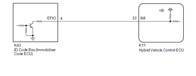
CAUTION / NOTICE / HINT
NOTICE:
-
When using the GTS with the ignition switch off, perform lock and unlock operations using the door control switch of the multiplex network master switch assembly at intervals of 1.5 seconds or less until communication between the GTS and the Toyota Prius vehicle begins, and then select the vehicle model manually.
Then select Model Code "KEY REGIST" under manual mode and enter the following menus: Body Electrical / Smart Key(CAN). While using the GTS, periodically perform lock and unlock operations using the door control switch of the multiplex network master switch assembly at intervals of 1.5 seconds or less to maintain communication between the GTS and the Toyota Prius vehicle.
-
The smart key system (for Start Function) uses the LIN communication system and CAN communication system. Inspect the communication function by following How to Proceed with Troubleshooting. Troubleshoot the smart key system (for Start Function) after confirming that the communication systems are functioning properly.
Click here

-
Before replacing the hybrid Toyota Prius vehicle control ECU or ID code box (immobiliser code ECU), refer to Registration.
Click here

- After performing repairs, confirm that no DTCs are output by performing "DTC Output Confirmation Operation".
-
When the hybrid vehicle control ECU is replaced, update the ECU security key.
Click here

HINT:
When DTC B279A12 and the certification ECU (smart key ECU assembly) DTC are output simultaneously, first perform troubleshooting for the certification ECU (smart key ECU assembly) DTC.
PROCEDURE
| 1. | CHECK CONNECTION OF CONNECTOR |
Pre-procedure1
(a) Turn the ignition switch off.
Procedure1
(b) Check that the connectors are properly connected to the hybrid Toyota Prius vehicle control ECU and ID code box (immobiliser code ECU).
OK:
Connectors are properly connected.
Post-procedure1
(c) None
| NG |

| CONNECT CONNECTORS PROPERLY |
|

| 2. | CHECK HYBRID Toyota Prius Vehicle CONTROL ECU (TERMINAL IMI) |
(a) Using an oscilloscope, check the waveform.

| *a | Component with harness connected (Hybrid Toyota Prius Vehicle Control ECU) | *b | Waveform |
| *c | Approximately 160 ms. | *d | Approximately 270 ms. |
OK:
 Click Location & Routing(K11) Click Connector(K11)
 | Tester Connection | Condition | Tool Setting | Specified Condition |
|---|---|---|---|
| K11-53 (IMI) - Body ground | Within 3 seconds of hybrid control system start or within 3 seconds of ignition switch turned to ON after cable disconnected and reconnected to auxiliary battery | 2 V/DIV., 500 ms./DIV. | Pulse generation (See waveform) |
| Result | Proceed to |
|---|---|
| 11 to 14 V | A |
| Below 1 V | B |
| Normal waveform |
| B |

| REPLACE HYBRID Toyota Prius Vehicle CONTROL ECU
|


|

| 3. | CHECK HARNESS AND CONNECTOR (ID CODE BOX (IMMOBILISER CODE ECU) - HYBRID Toyota Prius Vehicle CONTROL ECU) |
Pre-procedure1
(a) Disconnect the K11 hybrid vehicle control ECU connector.
(b) Disconnect the K43 ID code box (immobiliser code ECU) connector.
Procedure1
(c) Measure the resistance according to the value(s) in the table below.
Standard Resistance:
 Click Location & Routing(K43,K11) Click Connector(K43) Click Connector(K11)
 | Tester Connection | Condition | Specified Condition | Result |
|---|---|---|---|
| K43-4 (EFIO) - K11-53 (IMI) | Always | Below 1 Ω | Ω |
Post-procedure1
(d) None
| OK |

| REPLACE ID CODE BOX (IMMOBILISER CODE ECU)
|


| NG |

| REPAIR OR REPLACE HARNESS OR CONNECTOR |
Engine Immobiliser System Incorrect Assembly (B279C95)
DESCRIPTION
If a hybrid vehicle control ECU that is incompatible with the immobiliser function is installed, the hybrid vehicle control ECU will store this DTC.
| DTC No. | Detection Item | DTC Detection Condition | Trouble Area | DTC Output from | Priority | Note |
|---|---|---|---|---|---|---|
| B279C95 | Engine Immobiliser System Incorrect Assembly | A hybrid Toyota Prius vehicle control ECU that is incompatible with the immobiliser function is installed. (1-trip detection logic*) | Hybrid vehicle control ECU | Hybrid Control | A | - |
- *: Only detected while a malfunction is present.
| Vehicle Condition when Malfunction Detected | Fail-safe Function when Malfunction Detected |
|---|---|
| Hybrid control system cannot be started | - |
| DTC No. | Data List and Active Test |
|---|---|
| B279C95 | - |
CAUTION / NOTICE / HINT
NOTICE:
-
When using the GTS with the ignition switch off, perform lock and unlock operations using the door control switch of the multiplex network master switch assembly at intervals of 1.5 seconds or less until communication between the GTS and the Toyota Prius vehicle begins, and then select the vehicle model manually.
Then select Model Code "KEY REGIST" under manual mode and enter the following menus: Body Electrical / Smart Key(CAN). While using the GTS, periodically perform lock and unlock operations using the door control switch of the multiplex network master switch assembly at intervals of 1.5 seconds or less to maintain communication between the GTS and the Toyota Prius vehicle.
-
The smart key system (for Start Function) uses the LIN communication system and CAN communication system. Inspect the communication function by following How to Proceed with Troubleshooting. Troubleshoot the smart key system (for Start Function) after confirming that the communication systems are functioning properly.
Click here

-
Before replacing the hybrid Toyota Prius vehicle control ECU, refer to Registration.
Click here

- After performing repairs, confirm that no DTCs are output by performing "DTC Output Confirmation Operation".
-
When the hybrid vehicle control ECU is replaced, update the ECU security key.
Click here

PROCEDURE
| 1. | REPLACE HYBRID Toyota Prius Vehicle CONTROL ECU |
(a) Temporarily replace the hybrid vehicle control ECU with a new one.
HINT:
Click here


| NEXT |

| END (HYBRID Toyota Prius Vehicle CONTROL ECU WAS DEFECTIVE) |
Front Floor Electrical Key Oscillator Circuit Open (B27A513)
DESCRIPTION
The certification ECU (smart key ECU assembly) generates a request signal and transmits the signal to the No. 1 indoor electrical key antenna assembly (front floor). For the No. 1 indoor electrical key antenna assembly (front floor) to detect when the electrical key transmitter sub-assembly is in the cabin, the signal from the certification ECU (smart key ECU assembly) requesting a response from the electrical key transmitter sub-assembly is transmitted inside the Toyota Prius vehicle. DTC B27A513 is stored by the certification ECU (smart key ECU assembly) when an open is detected between the certification ECU (smart key ECU assembly) and No. 1 indoor electrical key antenna assembly (front floor) (between terminals CLG5 and ANTE5, or terminals CG5B and CLGB).
| DTC No. | Detection Item | DTC Detection Condition | Trouble Area | DTC Output from | Priority | Note |
|---|---|---|---|---|---|---|
| B27A513 | Front Floor Electrical Key Oscillator Circuit Open | An open is detected in the circuit between the certification ECU (smart key ECU assembly) and No. 1 indoor electrical key antenna assembly (front floor) (CLG5 - ANTE5, CG5B - CLGB) (1 trip detection logic*). |
| Smart Key | A | DTC Output Confirmation Operation:
|
- *: Only output while a malfunction is present.
| Vehicle Condition when Malfunction Detected | Fail-safe Operation when Malfunction Detected |
|---|---|
| When electrical key transmitter sub-assembly is in front seat area:
| - |
| DTC No. | Data List and Active Test |
|---|---|
| B27A513 | Key diagnostic mode can be used to perform troubleshooting |
WIRING DIAGRAM
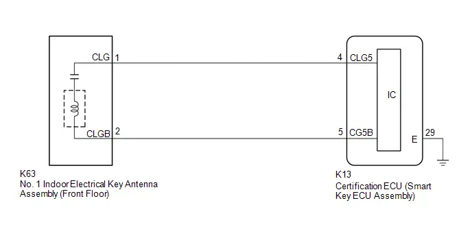
CAUTION / NOTICE / HINT
NOTICE:
-
When using the GTS with the ignition switch off, perform lock and unlock operations using the door control switch of the multiplex network master switch assembly at intervals of 1.5 seconds or less until communication between the GTS and the Toyota Prius vehicle begins, and then select the vehicle model manually.
Then select Model Code "KEY REGIST" under manual mode and enter the following menus: Body Electrical / Smart Key(CAN). While using the GTS, periodically perform lock and unlock operations using the door control switch of the multiplex network master switch assembly at intervals of 1.5 seconds or less to maintain communication between the GTS and the Toyota Prius vehicle.
-
The smart key system (for Start Function) uses the LIN communication system and CAN communication system. Inspect the communication function by following How to Proceed with Troubleshooting. Troubleshoot the smart key system (for Start Function) after confirming that the communication systems are functioning properly.
Click here

-
Before replacing the certification ECU (smart key ECU assembly), refer to Registration.
Click here

- After repair, confirm that no DTCs are output by performing "DTC Output Confirmation Operation".
PROCEDURE
| 1. | CHECK CONNECTOR CONNECTION |
(a) Check that the connectors are properly connected to the certification ECU (smart key ECU assembly) and No. 1 indoor electrical key antenna assembly (front floor).
OK:
Connectors are properly connected.
| NG |

| CONNECT CONNECTORS PROPERLY |
|

| 2. | CHECK HARNESS AND CONNECTOR (CERTIFICATION ECU (SMART KEY ECU ASSEMBLY) - NO. 1 INDOOR ELECTRICAL KEY ANTENNA ASSEMBLY (FRONT FLOOR)) |
Pre-procedure1
(a) Disconnect the K13 certification ECU (smart key ECU assembly) connector.
(b) Disconnect the K63 No. 1 indoor electrical key antenna assembly (front floor) connector.
Procedure1
(c) Measure the resistance according to the value(s) in the table below.
Standard Resistance:
 Click Location & Routing(K13,K63) Click Connector(K13) Click Connector(K63)
 | Tester Connection | Condition | Specified Condition | Result |
|---|---|---|---|
| K13-4 (CLG5) - K63-1 CLG) | Always | Below 1 Ω | Ω |
| K13-5 (CG5B) - K63-2 (CLGB) | Always | Below 1 Ω | Ω |
Post-procedure1
(d) Connect the K13 certification ECU (smart key ECU assembly) connector.
| NG |

| REPAIR OR REPLACE HARNESS OR CONNECTOR |
|

| 3. | CHECK CERTIFICATION ECU (SMART KEY ECU ASSEMBLY) (OUTPUT TO NO. 1 INDOOR ELECTRICAL KEY ANTENNA ASSEMBLY (FRONT FLOOR)) |
(a) Using an oscilloscope, check the waveform.
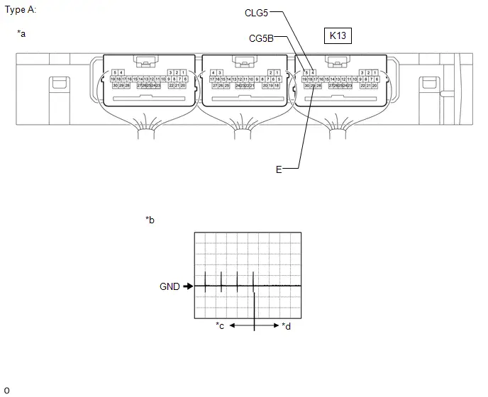
| *a | Component with harness connected (Certification ECU (Smart Key ECU Assembly)) | *b | Waveform |
| *c | For 30 seconds after any door closed | *d | After 30 seconds or more have elapsed since any door closed |
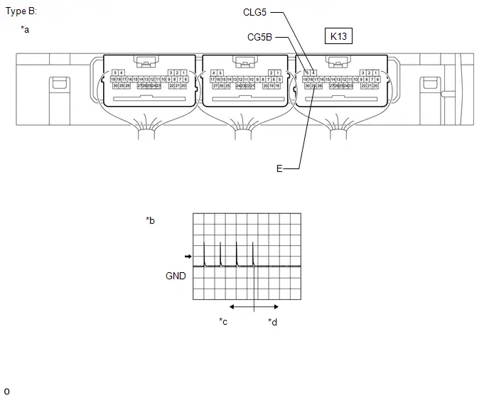
| *a | Component with harness connected (Certification ECU (Smart Key ECU Assembly)) | *b | Waveform |
| *c | For 30 seconds after any door closed | *d | After 30 seconds or more have elapsed since any door closed |
OK:
 Click Location & Routing(K13) Click Connector(K13)
 | Tester Connection | Condition | Tool Setting | Specified Condition |
|---|---|---|---|
| K13-4 (CLG5) - K13-29 (E) | Procedure:
| 5 V/DIV., 500 ms./DIV. | Pulse generation (See waveform) |
| K13-5 (CG5B) - K13-29 (E) | Procedure:
| 5 V/DIV., 500 ms./DIV. | Pulse generation (See waveform) |
| OK |

| REPLACE NO. 1 INDOOR ELECTRICAL KEY ANTENNA ASSEMBLY (FRONT FLOOR) |
| NG |

| REPLACE CERTIFICATION ECU (SMART KEY ECU ASSEMBLY)
|


Rear Floor 2 Electrical Key Oscillator Circuit Open (B27A713)
DESCRIPTION
The certification ECU (smart key ECU assembly) generates a request signal and transmits the signal to the No. 2 indoor electrical key antenna assembly (rear floor). For the No. 2 indoor electrical key antenna assembly (rear floor) to detect when the electrical key transmitter sub-assembly is in the cabin, the signal from the certification ECU (smart key ECU assembly) requesting a response from the electrical key transmitter sub-assembly is transmitted inside the Toyota Prius vehicle. DTC B27A713 is stored by the certification ECU (smart key ECU assembly) when an open is detected between the certification ECU (smart key ECU assembly) and No. 2 indoor electrical key antenna assembly (rear floor) (between terminals CLG7 and ANTE7, or terminals CG7B and CLGB).
| DTC No. | Detection Item | DTC Detection Condition | Trouble Area | DTC Output from | Priority | Note |
|---|---|---|---|---|---|---|
| B27A713 | Rear Floor 2 Electrical Key Oscillator Circuit Open | An open is detected in the circuit between the certification ECU (smart key ECU assembly) and No. 2 indoor electrical key antenna assembly (rear floor) (CLG7 - ANTE7, CG7B - CLGB) (1 trip detection logic*). |
| Smart Key | A | DTC Output Confirmation Operation:
|
- *: Only output while a malfunction is present.
| Vehicle Condition when Malfunction Detected | Fail-safe Operation when Malfunction Detected |
|---|---|
| When electrical key transmitter sub-assembly is in rear floor:
| - |
| DTC No. | Data List and Active Test |
|---|---|
| B27A713 | Key diagnostic mode can be used to perform troubleshooting |
WIRING DIAGRAM

CAUTION / NOTICE / HINT
NOTICE:
-
The smart key system (for Start Function) uses the LIN communication system and CAN communication system. Inspect the communication function by following How to Proceed with Troubleshooting. Troubleshoot the smart key system (for Start Function) after confirming that the communication systems are functioning properly.
Click here

-
When using the GTS with the ignition switch off, perform lock and unlock operations using the door control switch of the multiplex network master switch assembly at intervals of 1.5 seconds or less until communication between the GTS and the Toyota Prius vehicle begins, and then select the vehicle model manually.
Then select Model Code "KEY REGIST" under manual mode and enter the following menus: Body Electrical / Smart Key(CAN). While using the GTS, periodically perform lock and unlock operations using the door control switch of the multiplex network master switch assembly at intervals of 1.5 seconds or less to maintain communication between the GTS and the Toyota Prius vehicle.
-
Before replacing the certification ECU (smart key ECU assembly), refer to Registration.
Click here

- After repair, confirm that no DTCs are output by performing "DTC Output Confirmation Operation".
PROCEDURE
| 1. | CHECK CONNECTOR CONNECTION |
(a) Check that the connectors are properly connected to the certification ECU (smart key ECU assembly) and No. 2 indoor electrical key antenna assembly (rear floor).
OK:
Connectors are properly connected.
| NG |

| CONNECT CONNECTORS PROPERLY |
|

| 2. | CHECK HARNESS AND CONNECTOR (CERTIFICATION ECU (SMART KEY ECU ASSEMBLY) - NO. 2 INDOOR ELECTRICAL KEY ANTENNA ASSEMBLY (REAR FLOOR)) |
Pre-procedure1
(a) Disconnect the R59 certification ECU (smart key ECU assembly) connector.
(b) Disconnect the R48 No. 2 indoor electrical key antenna assembly (rear floor) connector.
Procedure1
(c) Measure the resistance according to the value(s) in the table below.
Standard Resistance:
 Click Location & Routing(R59,R48) Click Connector(R59) Click Connector(R48)
 | Tester Connection | Condition | Specified Condition | Result |
|---|---|---|---|
| R59-10 (CLG7) - R48-1 (CLG) | Always | Below 1 Ω | Ω |
| R59-9 (CG7B) - R48-2 (CLGB) | Always | Below 1 Ω | Ω |
Post-procedure1
(d) Connect the R59 certification ECU (smart key ECU assembly) connector.
| NG |

| REPAIR OR REPLACE HARNESS OR CONNECTOR |
|

| 3. | CHECK CERTIFICATION ECU (SMART KEY ECU ASSEMBLY) (OUTPUT TO NO. 2 INDOOR ELECTRICAL KEY ANTENNA ASSEMBLY (REAR FLOOR)) |
(a) Using an oscilloscope, check the waveform.

| *a | Component with harness connected (Certification ECU (Smart Key ECU Assembly)) | *b | Waveform |
| *c | For 30 seconds after any door closed | *d | After 30 seconds or more have elapsed since any door closed |

| *a | Component with harness connected (Certification ECU (Smart Key ECU Assembly)) | *b | Waveform |
| *c | For 30 seconds after any door closed | *d | After 30 seconds or more have elapsed since any door closed |
OK:
 Click Location & Routing(R59,K13) Click Connector(R59) Click Connector(K13)
 | Tester Connection | Condition | Tool Setting | Specified Condition |
|---|---|---|---|
| R59-10 (CLG7) - K13-29 (E) | Procedure:
| 5 V/DIV., 500 ms./DIV. | Pulse generation (See waveform) |
| R59-9 (CG7B) - K13-29 (E) | Procedure:
| 5 V/DIV., 500 ms./DIV. | Pulse generation (See waveform) |
| OK |

| REPLACE NO. 2 INDOOR ELECTRICAL KEY ANTENNA ASSEMBLY (REAR FLOOR)
|


| NG |

| REPLACE CERTIFICATION ECU (SMART KEY ECU ASSEMBLY)
|


Brake Switch "A" Signal Compare Failure (P057162)
DESCRIPTION
This DTC is stored when the brake signal sent via direct line and the brake signal sent via CAN communication do not match.
| DTC No. | Detection Item | DTC Detection Condition | Trouble Area | DTC Output from | Priority | Note |
|---|---|---|---|---|---|---|
| P057162 | Brake Switch "A" Signal Compare Failure | The brake signal sent via direct line and the brake signal sent via CAN communication do not match. (1-trip detection logic*) |
| Power Source Control | A | DTC Output Confirmation Operation:
|
- *: Only detected while a malfunction is present and the ignition switch is ON.
| Vehicle Condition when Malfunction Detected | Fail-safe Function when Malfunction Detected |
|---|---|
| - |
| DTC No. | Data List and Active Test |
|---|---|
| P057162 | Power Source Control
|
WIRING DIAGRAM
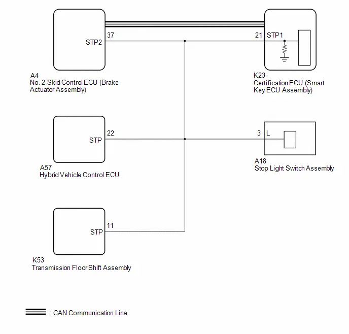
CAUTION / NOTICE / HINT
NOTICE:
-
When using the GTS with the ignition switch off, perform lock and unlock operations using the door control switch of the multiplex network master switch assembly at intervals of 1.5 seconds or less until communication between the GTS and the Toyota Prius vehicle begins, and then select the vehicle model manually.
Then select Model Code "KEY REGIST" under manual mode and enter the following menus: Body Electrical / Smart Key(CAN). While using the GTS, periodically perform lock and unlock operations using the door control switch of the multiplex network master switch assembly at intervals of 1.5 seconds or less to maintain communication between the GTS and the Toyota Prius vehicle.
-
The smart key system (for Start Function) uses the LIN communication system and CAN communication system. Inspect the communication function by following How to Proceed with Troubleshooting. Troubleshoot the smart key system (for Start Function) after confirming that the communication systems are functioning properly.
Click here

- When disconnecting the cable from the negative (-) auxiliary battery terminal, some systems need to be initialized after the cable is reconnected.
-
Before replacing the certification ECU (smart key ECU assembly), refer to Registration.
Click here

- After repair, confirm that no DTCs are output by performing "DTC Output Confirmation Operation".
PROCEDURE
| 1. | READ VALUE USING GTS (STOP LIGHT SWITCH) |
(a) Read the Data List according to the display on the GTS.
Body Electrical > Power Source Control > Data List| Tester Display | Measurement Item | Range | Normal Condition | Diagnostic Note |
|---|---|---|---|---|
| Stop Light Switch | State of brake pedal | OFF or ON | OFF: Brake pedal released |
|
| Tester Display |
|---|
| Stop Light Switch |
OK:
The GTS display changes correctly in response to the brake pedal operation.
| Result | Proceed to |
|---|---|
| The value of Stop Light Switch is OFF | A |
| The value of Stop Light Switch is not OFF | B |
| B |

| GO TO STEP 3 |
|

| 2. | READ VALUE USING GTS (STOP LIGHT SWITCH) |
(a) Read the Data List according to the display on the GTS.
Body Electrical > Power Source Control > Data List| Tester Display | Measurement Item | Range | Normal Condition | Diagnostic Note |
|---|---|---|---|---|
| Stop Light Switch | State of brake pedal | OFF or ON | ON: Brake pedal depressed |
|
| Tester Display |
|---|
| Stop Light Switch |
OK:
The GTS display changes correctly in response to the brake pedal operation.
| Result | Proceed to |
|---|---|
| The value of Stop Light Switch is ON | A |
| The value of Stop Light Switch is not ON | B |
| A |

| GO TO ELECTRONICALLY CONTROLLED BRAKE SYSTEM (HOW TO PROCEED WITH TROUBLESHOOTING)
|


|

| 3. | CHECK HARNESS AND CONNECTOR (CERTIFICATION ECU (SMART KEY ECU ASSEMBLY) - STOP LIGHT SWITCH ASSEMBLY) |
Pre-procedure1
(a) Disconnect the K23 certification ECU (smart key ECU assembly) connector.
(b) Disconnect the A18 stop light switch assembly connector.
(c) Disconnect the A4 No. 2 skid control ECU (brake actuator assembly) connector.
(d) Disconnect the A57 hybrid Toyota Prius vehicle control ECU connector.
(e) Disconnect the K53 transmission floor shift assembly connector.
Procedure1
(f) Measure the resistance according to the value(s) in the table below.
Standard Resistance:
 Click Location & Routing(K23,A18) Click Connector(K23) Click Connector(A18)
 | Tester Connection | Condition | Specified Condition | Result |
|---|---|---|---|
| K23-21 (STP1) - A18-3 (L) | Always | Below 1 Ω | Ω |
Post-procedure1
(g) Connect the K23 certification ECU (smart key ECU assembly) connector.
(h) Connect the A18 stop light switch assembly connector.
| NG |

| REPAIR OR REPLACE HARNESS OR CONNECTOR |
|

| 4. | CHECK CERTIFICATION ECU (SMART KEY ECU ASSEMBLY) |
| (a) Measure the voltage according to the value(s) in the table below. Standard Voltage:  Click Location & Routing(K23) Click Connector(K23) Click Location & Routing(K23) Click Connector(K23)
Result:
|
|
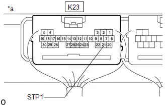
| OK |

| REPLACE CERTIFICATION ECU (SMART KEY ECU ASSEMBLY)
|


| NG |

| REPLACE STOP LIGHT SWITCH ASSEMBLY |
Lost Communication with Gear Shift Control Module "A" Missing Message (U010387,...,U113A87)
DESCRIPTION
These DTCs are stored when there is a CAN communication malfunction between the certification ECU (smart key ECU assembly) and transmission floor shift assembly, No. 2 skid control ECU (brake actuator assembly), main body ECU (multiplex network body ECU), combination meter assembly, radio and display receiver assembly, multiplex network door ECU*1, hybrid Toyota Prius vehicle control ECU, clearance warning ECU assembly or Solar energy control ECU assembly*2, and data from the option connector (bus buffer ECU) cannot be received.
- *1: w/ Power Back Door System
- *2: w/ Solar Charging System
| DTC No. | Detection Item | DTC Detection Condition | Trouble Area | DTC Output from | Priority | Note |
|---|---|---|---|---|---|---|
| U010387 | Lost Communication with Gear Shift Control Module "A" Missing Message | CAN communication error between certification ECU (smart key ECU assembly) and transmission floor shift assembly (1-trip detection logic*1) | Transmission floor shift assembly | Power Source Control | B | DTC Output Confirmation Operation:
|
| U012987 | Lost Communication with Brake System Control Module "A" Missing Message | CAN communication error between certification ECU (smart key ECU assembly) and No. 2 skid control ECU (brake actuator assembly) (1-trip detection logic*1) | No. 2 skid control ECU (brake actuator assembly) | Smart Key Power Source Control | B | DTC Output Confirmation Operation:
|
| U014087 | Lost Communication with Body Control Module Missing Message | CAN communication malfunction between certification ECU (smart key ECU assembly) and main body ECU (multiplex network body ECU) (1-trip detection logic*1) | Main body ECU (multiplex network body ECU) | Smart Key Power Source Control | B | DTC Output Confirmation Operation:
|
| U015587 | Lost Communication with Instrument Panel Cluster (IPC) Control Module | CAN communication malfunction between certification ECU (smart key ECU assembly) and combination meter assembly (1-trip detection logic*1) | Combination meter assembly | Smart Key Power Source Control | B | DTC Output Confirmation Operation:
|
| U016387 | Lost Communication with Navigation Control Module Missing Message | CAN communication malfunction between certification ECU (smart key ECU assembly) and radio and display receiver assembly (1-trip detection logic*1) | Radio and display receiver assembly | Smart Key Power Source Control | B | DTC Output Confirmation Operation:
|
| U023087 | Lost Communication with Rear Gate Module Missing Message | CAN communication malfunction between certification ECU (smart key ECU assembly) and multiplex network door ECU (1-trip detection logic*1)*2 | Multiplex network door ECU | Smart Key | B | DTC Output Confirmation Operation:
|
| U029387 | Lost Communication with Hybrid/EV Powertrain Control Module Missing Message | CAN communication error between certification ECU (smart key ECU assembly) and hybrid Toyota Prius vehicle control ECU (1-trip detection logic*1) | Hybrid vehicle control ECU | Smart Key Power Source Control | B | DTC Output Confirmation Operation:
|
| U111087 | Lost Communication with Intuitive Parking Assist Module Missing Message | CAN communication error between certification ECU (smart key ECU assembly) and clearance warning ECU assembly (1-trip detection logic*1) | Clearance warning ECU assembly | Smart Key Power Source Control | B | DTC Output Confirmation Operation:
|
| U111787 | Lost Communication with Accessory Gateway Missing Message | CAN communication malfunction between the certification ECU (smart key ECU assembly) and the option connector (bus buffer ECU) for approximately 10 seconds or more. | Option connector (bus buffer ECU) | Smart Key Power Source Control | B | DTC Output Confirmation Operation:
|
| U113A87 | Lost Communication with Solar Charging Control Module Missing Message | CAN communication malfunction between certification ECU (smart key ECU assembly) and solar energy control unit (1-trip detection logic*1)*3 | Solar energy control ECU assembly | Power Source Control | B | DTC Output Confirmation Operation:
|
- *1: Only detected while a malfunction is present.
- *2: w/ Power Back Door System
- *3: Solar Charging System
| DTC Code | Vehicle Condition when Malfunction Detected | Fail-safe Function when Malfunction Detected |
|---|---|---|
| U010387 | The Toyota Prius vehicle power source mode cannot be turned off by the automatic P position function. (it is possible for the power source to be turned off by manually selecting the P position) | - |
| U012987 | There is no effect on Toyota Prius vehicle behavior. | - |
| U014087 |
| - |
| U015587 | The warning (meter buzzer) does not sound and no warning messages displayed on the multi-information display. | - |
| U016387 | "ACC customize" (ACC power source enabled) remains "ON" | - |
| U023087*1 | Power back door system does not operate. | - |
| U029387 | There is no effect on Toyota Prius vehicle behavior. | - |
| U111087 |
| - |
| U111787 | The hybrid control system cannot be started using the wireless remote control function. | - |
| U113A87*3 | Solar charging system does not operate. | - |
- *1: w/ Power Back Door System
- *2: w/ Advanced Park (Remote Controlled Function)
- *3: Solar Charging System
| DTC No. | Data List and Active Test |
|---|---|
| U010387 U012987 U014087 U015587 U016387 U023087*1 U029387 U111087 U111787 U113A87*2 | - |
- *1: w/ Power Back Door System
- *2: Solar Charging System
CAUTION / NOTICE / HINT
NOTICE:
-
When using the GTS with the ignition switch off, perform lock and unlock operations using the door control switch of the multiplex network master switch assembly at intervals of 1.5 seconds or less until communication between the GTS and the Toyota Prius vehicle begins, and then select the vehicle model manually.
Then select Model Code "KEY REGIST" under manual mode and enter the following menus: Body Electrical / Smart Key(CAN). While using the GTS, periodically perform lock and unlock operations using the door control switch of the multiplex network master switch assembly at intervals of 1.5 seconds or less to maintain communication between the GTS and the Toyota Prius vehicle.
- After repair, confirm that no DTCs are output by performing "DTC Output Confirmation Operation".
HINT:
When the cable is disconnected and reconnected to the negative (-) auxiliary battery terminal, the power source mode returns to the state it was in before the cable was disconnected.
PROCEDURE
| 1. | CHECK FOR DTC |
(a) Check for DTCs and note any DTCs that are output.
| Result | Proceed to |
|---|---|
| U010387, U012987, U014087, U015587, U016387, U023087, U029387, U111087, U111787 or U113A87 is output | A |
| DTCs other than U010387, U012987, U014087, U015587, U016387, U023087, U029387, U111087, U111787 and U113A87 are output | B |
| B |

| GO TO DIAGNOSTIC TROUBLE CODE CHART |
|

| 2. | CLEAR DTC |
(a) Clear the DTCs.
(b) Turn the ignition switch off.
|

| 3. | CHECK FOR DTC |
(a) Turn the ignition switch to ON and wait for 10 seconds or more.
(b) Check for DTCs and note any DTCs that are output.
| Result | Proceed to |
|---|---|
| U010387, U012987, U014087, U015587, U016387, U023087, U029387, U111087, U111787 or U113A87 is output | A |
| U010387, U012987, U014087, U015587, U016387, U023087, U029387, U111087, U111787 and U113A87 are not output | B |
| A |

| GO TO CAN COMMUNICATION SYSTEM (HOW TO PROCEED WITH TROUBLESHOOTING) for PHEV Model: Click here
for HEV Model: Click here
|


| B |

| GO TO CHECK FOR INTERMITTENT PROBLEMS |
Power Source Mode does not Change to ON (IG and ACC)
DESCRIPTION
When the ignition switch cannot be turned to ACC or ON, interior verification may be abnormal or there may be a malfunction in the ACC relay or IG relay circuit. If interior verification cannot be performed, the certification ECU (smart key ECU assembly) may be malfunctioning or communication may not be possible between the No. 1 indoor electrical key antenna assembly (front floor), No. 2 indoor electrical key antenna assembly (rear floor) and the electrical key transmitter sub-assembly and electrical key and tire pressure monitoring system receiver assembly.
When an electrical key transmitter sub-assembly is brought into the cabin, its key ID code is compared with the key ID code stored in the certification ECU (smart key ECU assembly). If these codes do not match, key verification will fail and the ignition switch will not be able to be turned to ACC or ON.
When a door is unlocked and an electrical key transmitter sub-assembly is brought into the cabin, the certification ECU (smart key ECU assembly) activates the indoor electrical key antenna assemblies to form the interior detection area. The electrical key transmitter sub-assembly then responds to the detection signals with its key ID code. This response signal is received by the electrical key and tire pressure monitoring system receiver assembly and sent to the certification ECU (smart key ECU assembly).
Related Data List and Active Test Items| Problem Symptom | Data List and Active Test |
|---|---|
| Power source mode does not change to ON or on ACC | Power Source Control
|
WIRING DIAGRAM


CAUTION / NOTICE / HINT
NOTICE:
-
When using the GTS with the ignition switch off, perform lock and unlock operations using the door control switch of the multiplex network master switch assembly at intervals of 1.5 seconds or less until communication between the GTS and the Toyota Prius vehicle begins, and then select the vehicle model manually.
Then select Model Code "KEY REGIST" under manual mode and enter the following menus: Body Electrical / Smart Key(CAN). While using the GTS, periodically perform lock and unlock operations using the door control switch of the multiplex network master switch assembly at intervals of 1.5 seconds or less to maintain communication between the GTS and the Toyota Prius vehicle.
-
The smart key system (for Start Function) uses the LIN communication system and CAN communication system. Inspect the communication function by following How to Proceed with Troubleshooting. Troubleshoot the smart key system (for Start Function) after confirming that the communication systems are functioning properly.
Click here

- Make sure that no DTCs are output. If any DTCs are output, proceed to Diagnostic Trouble Code Chart.
-
If the smart key system (for Start Function) has been disabled, enable the system before performing troubleshooting.
Click here

- Inspect the fuses for circuits related to this system before performing the following procedure.
-
Before replacing the certification ECU (smart key ECU assembly) or an electrical key transmitter sub-assembly, refer to Registration.
Click here

- After completing repairs, confirm that the problem does not recur.
- After performing repairs, confirm that no DTCs are output by performing "DTC Output Confirmation Operation."
- The indoor electrical key antenna assemblies have an antenna coil between each terminal.
- The electrical key and tire pressure monitoring system receiver assembly is also related to interior certification.
HINT:
- If interior verification is unsuccessful, Operation History may be stored.
- If Operation History has been stored, refer to the Operation History List to determine the detection conditions and narrow down trouble areas.
| Tester Display |
|---|
| Toyota Prius Vehicle Control History (RoB) |
PROCEDURE
| 1. | CHECK POWER SOURCE MODE |
(a) Get into the vehicle while carrying the electrical key transmitter sub-assembly that has already been registered.
(b) Move the shift position to P.
(c) Press the power switch with the brake pedal released and check that the power source mode changes.
Click here

| Result | Proceed to |
|---|---|
| Power source mode cannot be changed when electrical key transmitter sub-assembly is in push button start function operation range for front side | A |
| Power source mode cannot be changed when electrical key transmitter sub-assembly is in push button start function operation range for inside luggage compartment | B |
| Power source mode cannot be changed | C |
| B |

| GO TO STEP 6 |
| C |

| GO TO STEP 10 |
|

| 2. | CHECK WAVE ENVIRONMENT |
(a) Install the transmitter battery to the electrical key transmitter sub-assembly.
Click here

(b) Bring the electrical key transmitter sub-assembly near the No. 1 indoor electrical key antenna assembly (front floor) and perform a smart key system check.
Click here

NOTICE:
Communication may not be possible if the electrical key transmitter sub-assembly is within 0.2 m (0.656 ft.) of the No. 1 indoor electrical key antenna assembly (front floor).
HINT:
- As the effect of wave interference decreases by moving the electrical key transmitter sub-assembly close to each indoor electrical key antenna assembly, it may be possible to check whether wave interference is the cause of the problem.
- If the inspection result is that the problem only occurs in certain locations or at certain times of day, the possibility of wave interference is high. Also, added Toyota Prius vehicle components may cause wave interference. If installed, remove them and perform the operation check.
- There may be wave interference if the vehicle is near broadcasting antennas, large video displays, wireless garage door opener systems, wireless security cameras, home security systems, etc. In this case, move the Toyota Prius vehicle to a different location and check if there is any improvement.
- If a tool for checking radio waves, such as a signal strength meter, is available, move around the area while observing both the LF band (used by the vehicle antenna to form the detection area) and RF band (used by the electrical key transmitter sub-assembly for transmission) to check for locations where there is wave interference.
OK:
The hybrid control system starts when the electrical key transmitter sub-assembly is held near each indoor electrical key antenna assembly and the power switch is pressed with the brake pedal depressed.
| OK |

| AFFECTED BY WAVE INTERFERENCE |
|

| 3. | CHECK KEY DIAGNOSTIC MODE |
(a) Check the following antennas in key diagnostic mode.
| (b) Check the No. 1 indoor electrical key antenna assembly (front floor). When the electrical key transmitter sub-assembly is at either inspection point, check that the wireless buzzer sounds. HINT:
|
|

| Result | Proceed to |
|---|---|
| The wireless buzzer does not sound | A |
| The wireless buzzer sounds | B |
| B |

| AFFECTED BY WAVE INTERFERENCE |
|

| 4. | CHECK HARNESS AND CONNECTOR (CERTIFICATION ECU (SMART KEY ECU ASSEMBLY) - NO. 1 INDOOR ELECTRICAL KEY ANTENNA ASSEMBLY (FRONT FLOOR)) |
(a) Disconnect the K13 certification ECU (smart key ECU assembly) connector.
(b) Disconnect the K63 No. 1 indoor electrical key antenna assembly (front floor) connector.
(c) Measure the resistance according to the value(s) in the table below.
Standard Resistance:
 Click Location & Routing(K13,K63) Click Connector(K13) Click Connector(K63)
 | Tester Connection | Condition | Specified Condition |
|---|---|---|
| K13-4 (CLG5) - K63-1 (CLG) | Always | Below 1 Ω |
| K13-5 (CG5B) - K63-2 (CLGB) | Always | Below 1 Ω |
| K13-4 (CLG5) or K63-1 (CLG) - Other terminals and body ground | Always | 10 kΩ or higher |
| K13-5 (CG5B) or K63-2 (CLGB) - Other terminals and body ground | Always | 10 kΩ or higher |
| NG |

| REPAIR OR REPLACE HARNESS OR CONNECTOR |
|

| 5. | CHECK CERTIFICATION ECU (SMART KEY ECU ASSEMBLY) (OUTPUT TO NO. 1 INDOOR ELECTRICAL KEY ANTENNA ASSEMBLY (FRONT FLOOR)) |
(a) Connect the K13 certification ECU (smart key ECU assembly) connector.
(b) Using an oscilloscope, check the waveform.
OK:
 Click Location & Routing(K63) Click Connector(K63)
 | Tester Connection | Condition | Tool Setting | Specified Condition |
|---|---|---|---|
| K63-1 (CLG) - K63-2 (CLGB) | Procedure:
| 5 V/DIV., 500 ms./DIV. | Pulse generation (See waveform) |

| *a | Waveform |
| *b | For 30 seconds after closing any door |
| *c | After 30 seconds or more have elapsed since any door closed |

| *a | Waveform |
| *b | For 30 seconds after closing any door |
| *c | After 30 seconds or more have elapsed since any door closed |
| OK |

| REPLACE NO. 1 INDOOR ELECTRICAL KEY ANTENNA ASSEMBLY (FRONT FLOOR) |
| NG |

| REPLACE CERTIFICATION ECU (SMART KEY ECU ASSEMBLY)
|


| 6. | CHECK WAVE ENVIRONMENT |
(a) Install the transmitter battery to the electrical key transmitter sub-assembly.
Click here

(b) Bring the electrical key transmitter sub-assembly near the No. 2 indoor electrical key antenna assembly (rear floor) and perform a smart key system check.
Click here

NOTICE:
Communication may not be possible if the electrical key transmitter sub-assembly is within 0.2 m (0.656 ft.) of the center of the No. 2 indoor electrical key antenna assembly (rear floor).
HINT:
Check that the customize setting "Ignition Available Area" is set to "All".
HINT:
- As the effect of wave interference decreases by moving the electrical key transmitter sub-assembly close to each indoor electrical key antenna assembly, it may be possible to check whether wave interference is the cause of the problem.
- If the inspection result is that the problem only occurs in certain locations or at certain times of day, the possibility of wave interference is high. Also, added Toyota Prius vehicle components may cause wave interference. If installed, remove them and perform the operation check.
- There may be wave interference if the vehicle is near broadcasting antennas, large video displays, wireless garage door opener systems, wireless security cameras, home security systems, etc. In this case, move the Toyota Prius vehicle to a different location and check if there is any improvement.
- If a tool for checking radio waves, such as a signal strength meter, is available, move around the area while observing both the LF band (used by the vehicle antenna to form the detection area) and RF band (used by the electrical key transmitter sub-assembly for transmission) to check for locations where there is wave interference.
OK:
The hybrid control system starts when the electrical key transmitter sub-assembly is held near each indoor electrical key antenna assembly and the power switch is pressed with the brake pedal depressed.
| OK |

| AFFECTED BY WAVE INTERFERENCE |
|

| 7. | CHECK KEY DIAGNOSTIC MODE |
(a) Check the following antennas in key diagnostic mode.
| (b) Check the No. 2 indoor electrical key antenna assembly (rear floor). When the electrical key transmitter sub-assembly is at either inspection point, check that the wireless buzzer sounds. HINT:
|
|

| Result | Proceed to |
|---|---|
| The wireless buzzer does not sound | A |
| The wireless buzzer sounds | B |
| B |

| AFFECTED BY WAVE INTERFERENCE |
|

| 8. | CHECK HARNESS AND CONNECTOR (CERTIFICATION ECU (SMART KEY ECU ASSEMBLY) - NO. 2 INDOOR ELECTRICAL KEY ANTENNA ASSEMBLY (REAR FLOOR)) |
(a) Disconnect the R59 certification ECU (smart key ECU assembly) connector.
(b) Disconnect the R48 No. 2 indoor electrical key antenna assembly (rear floor) connector.
(c) Measure the resistance according to the value(s) in the table below.
Standard Resistance:
 Click Location & Routing(R59,R48) Click Connector(R59) Click Connector(R48)
 | Tester Connection | Condition | Specified Condition |
|---|---|---|
| R59-10 (CLG7) - R48-1 (CLG) | Always | Below 1 Ω |
| R59-9 (CG7B) - R48-2 (CLGB) | Always | Below 1 Ω |
| R59-10 (CLG7) or R48-1 (CLG) - Other terminals and body ground | Always | 10 kΩ or higher |
| R59-9 (CG7B) or R48-2 (CLGB) - Other terminals and body ground | Always | 10 kΩ or higher |
| NG |

| REPAIR OR REPLACE HARNESS OR CONNECTOR |
|

| 9. | CHECK CERTIFICATION ECU (SMART KEY ECU ASSEMBLY) (OUTPUT TO NO. 2 INDOOR ELECTRICAL KEY ANTENNA ASSEMBLY (REAR FLOOR)) |
(a) Connect the R59 certification ECU (smart key ECU assembly) connector.
(b) Using an oscilloscope, check the waveform.
OK:
 Click Location & Routing(R48) Click Connector(R48)
 | Tester Connection | Condition | Tool Setting | Specified Condition |
|---|---|---|---|
| R48-1 (CLG) - R48-2 (CLGB) | Procedure:
| 5 V/DIV., 500 ms/DIV. | Pulse generation (See waveform) |

| *a | Waveform |
| *b | For 30 seconds after closing any door |
| *c | After 30 seconds or more have elapsed since any door closed |
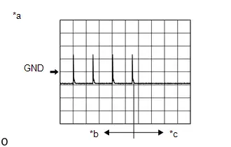
| *a | Waveform |
| *b | For 30 seconds after closing any door |
| *c | After 30 seconds or more have elapsed since any door closed |
| OK |

| REPLACE NO. 2 INDOOR ELECTRICAL KEY ANTENNA ASSEMBLY (REAR FLOOR)
|


| NG |

| REPLACE CERTIFICATION ECU (SMART KEY ECU ASSEMBLY)
|


| 10. | INSPECT TRANSMITTER BATTERY |
(a) Check the transmitter battery level of the electrical key transmitter sub-assembly that was checked first.
(1) Press and hold the lock switch of the electrical key transmitter sub-assembly for 5 seconds and check the number of times that the LED illuminates.
HINT:
-
The electrical key transmitter sub-assembly sends voltage information to the certification ECU (smart key ECU assembly) when it is being used. "Yes" is displayed for the Data List item Key Low Battery when this voltage information indicates 2.2 V or less.
Click here

- Even if the transmitter battery is depleted, it is still possible to start the hybrid control system by holding the electrical key transmitter sub-assembly near the power switch, depressing the brake pedal and pressing the power switch.
| Result | Proceed to |
|---|---|
| LED illuminates 3 times or more when switch is pressed and held | A |
| LED does not illuminate when switch is pressed and held | B |
| LED illuminates once or twice but not a third time | C |
| B |

| GO TO STEP 18 |
| C |

| REPLACE TRANSMITTER BATTERY |
|

| 11. | CHECK ENTRY LOCK / UNLOCK OPERATION |
(a) Check that the entry lock and unlock functions operate on each door.
Click here

HINT:
If the electrical key and tire pressure monitoring system receiver assembly is defective, code verification does not begin in the cabin and the entry lock and unlock functions do not operate.
| Result | Proceed to |
|---|---|
| Entry functions operate normally for all doors (w/ Wireless Charging System) | A |
| Entry functions operate normally for all doors (w/o Wireless Charging System) | B |
| An entry function does not operate normally for a door | C |
| B |

| GO TO STEP 13 |
| C |

| GO TO SMART KEY SYSTEM (for Entry Function) (All Door Entry Lock/Unlock Functions and Wireless Functions do not Operate) |
|

| 12. | CHECK WIRELESS CHARGING SYSTEM |
(a) Wireless charging system off.
Click here

(b) Check that interior verification is performed.
Click here

| Result | Proceed to |
|---|---|
| Interior verification is not performed normally | A |
| Interior verification is performed normally | B |
| B |

| GO TO WIRELESS CHARGING SYSTEM |
|

| 13. | READ VALUE USING GTS (PUSH START SWITCH 1, PUSH START SWITCH 2, PUSH START SWITCH 3) |
(a) Read the Data List according to the display on the GTS.
Body Electrical > Power Source Control > Data List| Tester Display | Measurement Item | Range | Normal Condition | Diagnostic Note |
|---|---|---|---|---|
| Push Start Switch 1 | Power switch 1 status | OFF or ON | OFF: Power switch not pressed ON: Power switch pressed |
|
| Push Start Switch 2 | Power switch 2 status | OFF or ON | OFF: Power switch not pressed ON: Power switch pressed |
|
| Push Start Switch 3 | Power switch 3 status | OFF or ON | OFF: Power switch not pressed ON: Power switch pressed |
|
| Tester Display |
|---|
| Push Start Switch 1 |
| Push Start Switch 2 |
| Push Start Switch 3 |
OK:
The value of "Start Switch1", "Start Switch2" and "Start Switch3" change correctly in response to the power switch operation.
| NG |

| GO TO STEP 16 |
|

| 14. | CHECK CERTIFICATION ECU (SMART KEY ECU ASSEMBLY) |
(a) Measure the voltage while checking the Data List on the GTS.
(1) Read the Data List according to the display on the GTS.

| *a | Component with harness connected (Certification ECU (Smart Key ECU Assembly)) | - | - |
| Tester Display | Measurement Item | Range | Normal Condition | Diagnostic Note |
|---|---|---|---|---|
| Power Supply Condition | Power supply state | OFF, ACC ON, IGR ON, IGP ON or Starter ON | OFF: Ignition switch off ACC ON: Ignition switch ACC IGR ON: Ignition switch ON IGP ON: Ignition switch ON Starter ON: Sending hybrid control system start request signal | - |
| Tester Display |
|---|
| Power Supply Condition |
(2) Measure the voltage according to the value(s) in the table below.
Standard Voltage:
 Click Location & Routing(K23,K13) Click Connector(K23) Click Connector(K13)
 | Tester Connection | Condition | Specified Condition |
|---|---|---|
| K23-11 (IGRD) - Body ground | Ignition switch off | Below 1 V |
| Ignition switch ACC | Below 1 V | |
| Ignition switch ON | 9 V or higher | |
| K23-24 (IGPD) - Body ground | Ignition switch off | Below 1 V |
| Ignition switch ACC | Below 1 V | |
| Ignition switch ON | 9 V or higher | |
| K13-21 (ACCD) - Body ground | Ignition switch off | Below 1 V |
| Ignition switch ACC | 8.5 V or higher | |
| Ignition switch ON | 8.5 V or higher |
| NG |

| REPLACE CERTIFICATION ECU (SMART KEY ECU ASSEMBLY)
|


|

| 15. | CHECK HARNESS AND CONNECTOR (POWER DISTRIBUTION BOX ASSEMBLY - BODY GROUND) |
(a) Disconnect the K20 power distribution box assembly connector.
(b) Measure the resistance according to the value(s) in the table below.
Standard Resistance:
 Click Location & Routing(K20) Click Connector(K20)
 | Tester Connection | Condition | Specified Condition |
|---|---|---|
| K20-36 - Body ground | Always | Below 1 Ω |
| OK |

| REPLACE POWER DISTRIBUTION BOX ASSEMBLY
|


| NG |

| REPAIR OR REPLACE HARNESS OR CONNECTOR |
| 16. | INSPECT POWER SWITCH |
Click here

| NG |

| REPLACE POWER SWITCH |
|

| 17. | CHECK HARNESS AND CONNECTOR (CERTIFICATION ECU (SMART KEY ECU ASSEMBLY) - POWER SWITCH) |
(a) Disconnect the K13 certification ECU (smart key ECU assembly) connector.
(b) Measure the resistance according to the value(s) in the table below.
Standard Resistance:
 Click Location & Routing(K13,K66) Click Connector(K13) Click Connector(K66)
 | Tester Connection | Condition | Specified Condition |
|---|---|---|
| K13-19 (SSW1) - K66-12 (SS1) | Always | Below 1 Ω |
| K13-27 (SSW2) - K66-6 (SS2) | Always | Below 1 Ω |
| K13-23 (SSW3) - K66-11 (SS3) | Always | Below 1 Ω |
| K13-30 (AGND) - K66-3 (GND) | Always | Below 1 Ω |
| K13-19 (SSW1) or K66-12 (SS1) - Other terminals and body ground | Always | 10 kΩ or higher |
| K13-27 (SSW2) or K66-6 (SS2) - Other terminals and body ground | Always | 10 kΩ or higher |
| K13-23 (SSW3) or K66-11 (SS3) - Other terminals and body ground | Always | 10 kΩ or higher |
| K13-30 (AGND) or K66-3 (GND) - Other terminals and body ground | Always | 10 kΩ or higher |
| OK |

| REPLACE CERTIFICATION ECU (SMART KEY ECU ASSEMBLY)
|


| NG |

| REPAIR OR REPLACE HARNESS OR CONNECTOR |
| 18. | INSPECT TRANSMITTER BATTERY |
NOTICE:
Do not wrap the lead wire ground a terminal, wedge it between terminals, or solder it. The terminal may be deformed or damaged, and the transmitter battery will not be able to be installed correctly.
Click here

| OK |

| REPLACE ELECTRICAL KEY TRANSMITTER SUB-ASSEMBLY |
| NG |

| REPLACE TRANSMITTER BATTERY |
Power Source Mode does not Change to ON (IG)
DESCRIPTION
If the power switch is pressed with the electrical key transmitter sub-assembly in the cabin, the certification ECU (smart key ECU assembly) receives a signal and changes the power source mode.
Related Data List and Active Test Items| Problem Symptom | Data List and Active Test |
|---|---|
| Power source mode does not change to ON but does change to ACC | Power Source Control
|
WIRING DIAGRAM

CAUTION / NOTICE / HINT
NOTICE:
-
When using the GTS with the ignition switch off, perform lock and unlock operations using the door control switch of the multiplex network master switch assembly at intervals of 1.5 seconds or less until communication between the GTS and the Toyota Prius vehicle begins, and then select the vehicle model manually.
Then select Model Code "KEY REGIST" under manual mode and enter the following menus: Body Electrical / Smart Key(CAN). While using the GTS, periodically perform lock and unlock operations using the door control switch of the multiplex network master switch assembly at intervals of 1.5 seconds or less to maintain communication between the GTS and the Toyota Prius vehicle.
-
The smart key system (for Start Function) uses the LIN communication system and CAN communication system. Inspect the communication function by following How to Proceed with Troubleshooting. Troubleshoot the smart key system (for Start Function) after confirming that the communication systems are functioning properly.
Click here

- Make sure that no DTCs are output. If any DTCs are output, proceed to Diagnostic Trouble Code Chart.
-
If the smart key system (for Start Function) has been disabled, enable the system before performing troubleshooting.
Click here

- Inspect the fuses for circuits related to this system before performing the following procedure.
-
Before replacing the certification ECU (smart key ECU assembly), refer to Registration.
Click here

- After completing repairs, confirm that the problem does not recur.
- After performing repairs, confirm that no DTCs are output by performing "DTC Output Confirmation Operation."
HINT:
- If interior verification is unsuccessful, Operation History may be stored.
- If Operation History has been stored, refer to the Operation History List to determine the detection conditions and narrow down trouble areas.
| Tester Display |
|---|
| Toyota Prius Vehicle Control History (RoB) |
PROCEDURE
| 1. | CHECK FOR DTC |
(a) Using the GTS, check for certification ECU (smart key ECU assembly) DTCs.
Body Electrical > Power Source Control > Trouble Codes Body Electrical > Smart Key > Trouble Codes| Result | Proceed to |
|---|---|
| DTCs are not output | A |
| Smart key system (for Start Function) DTCs are output | B |
| B |

| GO TO DIAGNOSTIC TROUBLE CODE CHART
|


|

| 2. | CHECK HARNESS AND CONNECTOR (POWER DISTRIBUTION BOX ASSEMBLY - CERTIFICATION ECU (SMART KEY ECU ASSEMBLY) AND BODY GROUND) |
(a) Disconnect the K23 certification ECU (smart key ECU assembly) connector.
(b) Disconnect the K20 and K21 power distribution box assembly connectors.
(c) Measure the resistance according to the value(s) in the table below.
Standard Resistance:
 Click Location & Routing(K21,K23,K20) Click Connector(K21) Click Connector(K23) Click Connector(K20)
 | Tester Connection | Condition | Specified Condition |
|---|---|---|
| K21-17 - K23-24 (IGPD) | Always | Below 1 Ω |
| K20-10 - K23-11 (IGRD) | Always | Below 1 Ω |
| K20-36 - Body ground | Always | Below 1 Ω |
| K21-17 or K23-24 (IGPD) - Other terminals and body ground | Always | 10 kΩ or higher |
| K20-10 or K23-11 (IGRD) - Other terminals and body ground | Always | 10 kΩ or higher |
| NG |

| REPAIR OR REPLACE HARNESS OR CONNECTOR |
|

| 3. | CHECK CERTIFICATION ECU (SMART KEY ECU ASSEMBLY) |
| (a) Connect the K23 certification ECU (smart key ECU assembly) connector. |
|

(b) Measure the voltage according to the value(s) in the table below.
Standard Voltage:
 Click Location & Routing(K23) Click Connector(K23)
 | Tester Connection | Condition | Specified Condition |
|---|---|---|
| K23-11 (IGRD) - Body ground | Ignition switch ACC → Ignition switch ON | 1 V or less → 9 V or higher |
| K23-24 (IGPD) - Body ground | Ignition switch ACC → Ignition switch ON | 1 V or less → 9 V or higher |
| NG |

| REPLACE CERTIFICATION ECU (SMART KEY ECU ASSEMBLY)
|


|

| 4. | CHECK HARNESS AND CONNECTOR (POWER DISTRIBUTION BOX ASSEMBLY - POWER SOURCE) |
(a) Disconnect the K23 certification ECU (smart key ECU assembly) connector.
(b) Disconnect the A13, A12, K20 and K21 power distribution box assembly connectors.
(c) Measure the voltage according to the value(s) in the table below.
Standard Voltage:
 Click Location & Routing(A13) Click Connector(A13)
 | Tester Connection | Condition | Specified Condition |
|---|---|---|
| A13-1 - Body ground | Ignition switch off | 11 to 14 V |
| NG |

| REPAIR OR REPLACE HARNESS OR CONNECTOR |
|

| 5. | CHECK POWER DISTRIBUTION BOX ASSEMBLY |
(a) Remove the power distribution box assembly.
Click here


(b) Remove the main body ECU (multiplex network body ECU) from the power distribution box assembly.

| *a | Component without harness connected (Power Distribution Box Assembly) | - | - |
(c) Measure the resistance according to the value(s) in the table below.
Standard Resistance:
 Click Location & Routing(K21,A12) Click Connector(K21) Click Connector(A12)
 | Tester Connection | Condition | Specified Condition |
|---|---|---|
| K21-17 - A12-14 | Always | Below 1 Ω |
(d) Connect the auxiliary battery terminal ( ) to the K20-10 terminal.
(e) Connect the auxiliary battery terminal (-) to the K20-36 terminal.
(f) Measure the resistance according to the value(s) in the table below.
Standard Resistance:
 Click Location & Routing(A13,K21,K20) Click Connector(A13) Click Connector(K20)
 | Tester Connection | Condition | Specified Condition |
|---|---|---|
| A13-1 - K21-36 | Auxiliary battery voltage applied between terminals K20-10 and K20-36 | Below 1 Ω |
| A13-1 - K20-39 | Auxiliary battery voltage applied between terminals K20-10 and K20-36 | Below 1 Ω |
| NG |

| REPLACE POWER DISTRIBUTION BOX ASSEMBLY
|


|

| 6. | CHECK HARNESS AND CONNECTOR (POWER DISTRIBUTION BOX ASSEMBLY - IGP RELAY) |
(a) Remove the IGP relay from the No. 1 engine room relay block and No. 1 junction block assembly.
(b) Measure the resistance according to the value(s) in the table below.
Standard Resistance:
 Click Location & Routing(A12) Click Connector(A12)
 | Tester Connection | Condition | Specified Condition |
|---|---|---|
| A12-14 - IGP relay terminal 2 | Always | Below 1 Ω |
| IGP relay terminal 1 - Body ground | Always | Below 1 Ω |
| A12-14 or IGP relay terminal 2 - Other terminals and body ground | Always | 10 kΩ or higher |
| NG |

| REPAIR OR REPLACE HARNESS OR CONNECTOR |
|

| 7. | INSPECT IGP RELAY |
| (a) Measure the resistance according to the value(s) in the table below. Standard Resistance:
|
|

| OK |

| REPAIR OR REPLACE HARNESS OR CONNECTOR |
| NG |

| REPLACE IGP RELAY |
Power Source Mode does not Change to ON (ACC)
DESCRIPTION
If the power switch is pressed with the electrical key transmitter sub-assembly in the cabin, the certification ECU (smart key ECU assembly) receives a signal and changes the power source mode.
Related Data List and Active Test Items| Problem Symptom | Data List and Active Test |
|---|---|
| Power source mode does not change to ACC but does change to ON | Power Source Control
|
WIRING DIAGRAM

CAUTION / NOTICE / HINT
NOTICE:
-
When using the GTS with the ignition switch off, perform lock and unlock operations using the door control switch of the multiplex network master switch assembly at intervals of 1.5 seconds or less until communication between the GTS and the Toyota Prius vehicle begins, and then select the vehicle model manually.
Then select Model Code "KEY REGIST" under manual mode and enter the following menus: Body Electrical / Smart Key(CAN). While using the GTS, periodically perform lock and unlock operations using the door control switch of the multiplex network master switch assembly at intervals of 1.5 seconds or less to maintain communication between the GTS and the Toyota Prius vehicle.
-
The smart key system (for Start Function) uses the LIN communication system and CAN communication system. Inspect the communication function by following How to Proceed with Troubleshooting. Troubleshoot the smart key system (for Start Function) after confirming that the communication systems are functioning properly.
Click here

- Make sure that no DTCs are output. If any DTCs are output, proceed to Diagnostic Trouble Code Chart.
-
If the smart key system (for Start Function) has been disabled, enable the system before performing troubleshooting.
Click here

- Inspect the fuses for circuits related to this system before performing the following procedure.
-
Before replacing the certification ECU (smart key ECU assembly), refer to Registration.
Click here

- After completing repairs, confirm that the problem does not recur.
- After performing repairs, confirm that no DTCs are output by performing "DTC Output Confirmation Operation."
PROCEDURE
| 1. | CHECK FOR DTC |
(a) Using the GTS, check for certification ECU (smart key ECU assembly) DTCs.
Body Electrical > Power Source Control > Trouble Codes Body Electrical > Smart Key > Trouble Codes| Result | Proceed to |
|---|---|
| DTCs are not output | A |
| Smart key system (for Start Function) DTCs are output | B |
| B |

| GO TO DIAGNOSTIC TROUBLE CODE CHART
|


|

| 2. | CHECK HARNESS AND CONNECTOR (POWER DISTRIBUTION BOX ASSEMBLY - POWER SOURCE) |
(a) Disconnect the A15 power distribution box assembly connector.
(b) Measure the voltage according to the value(s) in the table below.
Standard Voltage:
 Click Location & Routing(A15) Click Connector(A15)
 | Tester Connection | Condition | Specified Condition |
|---|---|---|
| A15-1 - Body ground | Ignition switch off | 11 to 14 V |
| NG |

| REPAIR OR REPLACE HARNESS OR CONNECTOR |
|

| 3. | CHECK POWER DISTRIBUTION BOX ASSEMBLY (ACC RELAY) |
(a) Remove the power distribution box assembly.
Click here


(b) Remove the main body ECU (multiplex network body ECU) from the power distribution box assembly.
(c) Connect the auxiliary battery terminal ( ) to the K20-38 terminal.
(d) Connect the auxiliary battery terminal (-) to the K20-36 terminal.

| *a | Component without harness connected (Power Distribution Box Assembly) | - | - |
(e) Measure the resistance according to the value(s) in the table below.
Standard Resistance:
 Click Location & Routing(A15,K20) Click Connector(A15) Click Connector(K20)
 | Tester Connection | Condition | Specified Condition |
|---|---|---|
| A15-1 - K20-12 | Auxiliary battery voltage applied between terminals K20-38 and K20-36 | Below 1 Ω |
| OK |

| REPAIR OR REPLACE HARNESS OR CONNECTOR |
| NG |

| REPLACE POWER DISTRIBUTION BOX ASSEMBLY
|


Power Source Mode does not Change to ON (READY)
DESCRIPTION
When the electrical key transmitter sub-assembly is in the cabin and the power switch is pressed, the certification ECU (smart key ECU assembly) receives a signal and changes the power source mode. Additionally, when the shift position is in P and the brake pedal is depressed, the hybrid control system can be started by pressing the power switch.
Related Data List and Active Test Items| Problem Symptom | Data List and Active Test |
|---|---|
| Power source mode does not change to ON (READY) | Power Source Control
Smart Key
|
WIRING DIAGRAM

CAUTION / NOTICE / HINT
NOTICE:
-
When using the GTS with the ignition switch off, perform lock and unlock operations using the door control switch of the multiplex network master switch assembly at intervals of 1.5 seconds or less until communication between the GTS and the Toyota Prius vehicle begins, and then select the vehicle model manually.
Then select Model Code "KEY REGIST" under manual mode and enter the following menus: Body Electrical / Smart Key(CAN). While using the GTS, periodically perform lock and unlock operations using the door control switch of the multiplex network master switch assembly at intervals of 1.5 seconds or less to maintain communication between the GTS and the Toyota Prius vehicle.
-
The smart key system (for Start Function) uses the LIN communication system and CAN communication system. Inspect the communication function by following How to Proceed with Troubleshooting. Troubleshoot the smart key system (for Start Function) after confirming that the communication systems are functioning properly.
Click here

-
If the smart key system (for Start Function) has been canceled, enable the system before performing troubleshooting.
Click here

- Inspect the fuses for circuits related to this system before performing the following procedure.
-
Before replacing the certification ECU (smart key ECU assembly) or electrical key transmitter sub-assembly, refer to Registration.
Click here

- After completing repairs, confirm that the problem does not recur.
- After repair, confirm that no DTCs are output by performing "DTC Output Confirmation Operation".
PROCEDURE
| 1. | CHECK POWER SWITCH CONDITION |
(a) Get into the Toyota Prius vehicle while carrying an electrical key transmitter sub-assembly.
(b) Move the shift position to P.
(c) With the brake pedal released, check that pressing the power switch causes the power source mode to change.
| Result | Proceed to |
|---|---|
| Power source mode changes : Off → ACC → ON → off | A |
| Power source mode does not change to ACC or ON | B |
| Power source mode changes to ON but not to ACC | C |
| Power source mode changes to ACC but not to ON | D |
| B |

| GO TO OTHER PROBLEM (Power Source Mode does not Change to ON (IG and ACC)) |
| C |

| GO TO OTHER PROBLEM (Power Source Mode does not Change to ON (ACC)) |
| D |

| GO TO OTHER PROBLEM (Power Source Mode does not Change to ON (IG)) |
|

| 2. | READ VALUE USING GTS (STOP LIGHT SWITCH) |
(a) Read the Data List according to the display on the GTS.
Body Electrical > Power Source Control > Data List| Tester Display | Measurement Item | Range | Normal Condition | Diagnostic Note |
|---|---|---|---|---|
| Stop Light Switch | State of brake pedal | OFF or ON | OFF: Brake pedal released ON: Brake pedal depressed |
|
| Tester Display |
|---|
| Stop Light Switch |
OK:
The GTS display changes correctly in response to the brake pedal operation.
| NG |

| GO TO STEP 10 |
|

| 3. | READ VALUE USING GTS (SHIFT P SIGNAL CONDITION (LINE)) |
(a) Read the Data List according to the display on the GTS.
Body Electrical > Power Source Control > Data List| Tester Display | Measurement Item | Range | Normal Condition | Diagnostic Note |
|---|---|---|---|---|
| Shift P Signal Condition (Line) | Shift position P | Shift P, Other than shift P, Shift N or Other than shift P/N | Shift P: Shift position in P Shift N: Shift position in N Other than shift P/N: Other than shift position in P or N | Use this item to determine if the shift position switch is malfunctioning. |
| Tester Display |
|---|
| Shift P Signal Condition (Line) |
OK:
The GTS display changes correctly in response to the shift position.
| NG |

| GO TO STEP 8 |
|

| 4. | READ VALUE USING GTS (POWER SUPPLY CONDITION) |
(a) Read the Data List according to the display on the GTS.
Body Electrical > Power Source Control > Data List| Tester Display | Measurement Item | Range | Normal Condition | Diagnostic Note |
|---|---|---|---|---|
| Power Supply Condition | Power supply state | OFF, ACC ON, IGR ON, IGP ON or Starter ON | OFF: Ignition switch off ACC ON: Ignition switch ACC IGR ON: Ignition switch ON IGP ON: Ignition switch ON Starter ON: Sending hybrid control system start request signal | - |
| Tester Display |
|---|
| Power Supply Condition |
NOTICE:
Check that the key indicator display is displayed on the multi-information display in the combination meter assembly, and then press the power switch.
OK:
The GTS display changes correctly in response to the power switch operation.
| NG |

| GO TO STEP 7 |
|

| 5. | CHECK HARNESS AND CONNECTOR (CERTIFICATION ECU (SMART KEY ECU ASSEMBLY) - HYBRID Toyota Prius Vehicle CONTROL ECU) |
(a) Disconnect the K23 certification ECU (smart key ECU assembly) connector.
(b) Disconnect the K11 hybrid vehicle control ECU connector.
(c) Measure the resistance according to the value(s) in the table below.
Standard Resistance:
 Click Location & Routing(K23,K11) Click Connector(K23) Click Connector(K11)
 | Tester Connection | Condition | Specified Condition |
|---|---|---|
| K23-2 (ST2) - K11-11 (ST2) | Always | Below 1 Ω |
| K23-2 (ST2) or K11-11 (ST2) - Other terminals and body ground | Always | 10 kΩ or higher |
| NG |

| REPAIR OR REPLACE HARNESS OR CONNECTOR |
|

| 6. | CHECK CERTIFICATION ECU (SMART KEY ECU ASSEMBLY) |
(a) Connect the K23 certification ECU (smart key ECU assembly) connector.
(b) Connect the K11 hybrid Toyota Prius vehicle control ECU connector.
| (c) Measure the voltage according to the value(s) in the table below. Standard Voltage:  Click Location & Routing(K23) Click Connector(K23) Click Location & Routing(K23) Click Connector(K23)
|
|

| OK |

| GO TO HYBRID CONTROL SYSTEM |
| NG |

| REPLACE CERTIFICATION ECU (SMART KEY ECU ASSEMBLY)
|


| 7. | CHECK SECURITY INDICATOR LIGHT (IMMOBILISER FUNCTION UNSET) |
(a) Get into the Toyota Prius vehicle while carrying an electrical key transmitter sub-assembly.
(b) Move the shift position to P.
(c) Press the power switch with the brake pedal released and check that the security indicator light changes from blinking to off at the same time that the power source mode changes to ACC.
OK:
The security indicator light changes from blinking to off at the same time that the power source mode changes to ACC.
HINT:
The immobiliser function can be determined to be operating correctly if the security indicator light changes from blinking to off at the same time that the power source mode changes to ACC.
| OK |

| REPLACE CERTIFICATION ECU (SMART KEY ECU ASSEMBLY)
|


| NG |

| GO TO OTHER PROBLEM (Immobiliser System does not Operate Properly) |
| 8. | CHECK TRANSMISSION FLOOR SHIFT ASSEMBLY |
| (a) Measure the voltage according to the value(s) in the table below. Standard Voltage:  Click Location & Routing(K13) Click Connector(K13) Click Location & Routing(K13) Click Connector(K13)
|
|
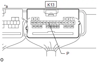
| OK |

| REPLACE CERTIFICATION ECU (SMART KEY ECU ASSEMBLY)
|


|

| 9. | CHECK HARNESS AND CONNECTOR (CERTIFICATION ECU (SMART KEY ECU ASSEMBLY) - TRANSMISSION FLOOR SHIFT ASSEMBLY) |
(a) Disconnect the K13 certification ECU (smart key ECU assembly) connector.
(b) Disconnect the K53 transmission floor shift assembly connector.
(c) Measure the resistance according to the value(s) in the table below.
Standard Resistance:
 Click Location & Routing(K13,K53) Click Connector(K13) Click Connector(K53)
 | Tester Connection | Condition | Specified Condition |
|---|---|---|
| K13-14 (P) - K53-7 (PPOS) | Always | Below 1 Ω |
| K13-14 (P) or K53-7 (PPOS) - Other terminals and body ground | Always | 10 kΩ or higher |
| OK |

| REPLACE TRANSMISSION FLOOR SHIFT ASSEMBLY |
| NG |

| REPAIR OR REPLACE HARNESS OR CONNECTOR |
| 10. | CHECK HARNESS AND CONNECTOR (STOP LIGHT SWITCH ASSEMBLY - POWER SOURCE AND BODY GROUND) |
| (a) Measure the voltage according to the value(s) in the table below. Standard Voltage:  Click Location & Routing(A18) Click Connector(A18) Click Location & Routing(A18) Click Connector(A18)
|
|

(b) Measure the resistance according to the value(s) in the table below.
Standard Resistance:
 Click Location & Routing(A18) Click Connector(A18)
 | Tester Connection | Condition | Specified Condition |
|---|---|---|
| A18-2 (GND) - Body ground | Always | Below 1 Ω |
| NG |

| REPAIR OR REPLACE HARNESS OR CONNECTOR |
|

| 11. | CHECK HARNESS AND CONNECTOR (CERTIFICATION ECU (SMART KEY ECU ASSEMBLY) - STOP LIGHT SWITCH ASSEMBLY) |
(a) Disconnect the K23 certification ECU (smart key ECU assembly) connector.
(b) Disconnect the A57 hybrid Toyota Prius vehicle control ECU connector.
(c) Disconnect the A18 stop light switch assembly connector.
(d) Disconnect the A4 No. 2 skid control ECU (brake actuator assembly) connector.
(e) Disconnect the K53 transmission floor shift assembly connector.
(f) Measure the resistance according to the value(s) in the table below.
Standard Resistance:
 Click Location & Routing(K23,A18) Click Connector(K23) Click Connector(A18)
 | Tester Connection | Condition | Specified Condition |
|---|---|---|
| K23-21 (STP1) - A18-2 (L) | Always | Below 1 Ω |
| K23-21 (STP1) or A18-2 (L) - Other terminals and body ground | Always | 10 kΩ or higher |
| NG |

| REPAIR OR REPLACE HARNESS OR CONNECTOR |
|

| 12. | CHECK STOP LIGHT SWITCH ASSEMBLY |
(a) Check the stop light switch assembly.
Click here

| OK |

| REPLACE CERTIFICATION ECU (SMART KEY ECU ASSEMBLY)
|


| NG |

| REPLACE STOP LIGHT SWITCH ASSEMBLY |
New Key cannot be Registered
DESCRIPTION
If a new electrical key transmitter sub-assembly could not be registered, wave interference or a malfunction of the certification ECU (smart key ECU assembly), electrical key transmitter sub-assembly, ID code box (immobiliser code ECU), electrical key and tire pressure monitoring system receiver assembly is suspected.
The registration procedure to add another electrical key transmitter sub-assembly (without replacing any parts) is called "additional key ID registration".
If additional registration is not possible, refer to Additional Key cannot be Registered.
Click here

HINT:
If any of the following have been performed, registration of all electrical key transmitter sub-assemblies is necessary:- The certification ECU (smart key ECU assembly) has been replaced.
- The certification ECU (smart key ECU assembly) and ID code box (immobiliser code ECU) have been replaced.
CAUTION / NOTICE / HINT
NOTICE:
- New registration mode can be entered only when no electrical key transmitter sub-assemblies are stored in the certification ECU (smart key ECU assembly).
-
When using the GTS with the ignition switch off, perform lock and unlock operations using the door control switch of the multiplex network master switch assembly at intervals of 1.5 seconds or less until communication between the GTS and the Toyota Prius vehicle begins, and then select the vehicle model manually.
Then select Model Code "KEY REGIST" under manual mode and enter the following menus: Body Electrical / Smart Key(CAN). While using the GTS, periodically perform lock and unlock operations using the door control switch of the multiplex network master switch assembly at intervals of 1.5 seconds or less to maintain communication between the GTS and the Toyota Prius vehicle.
-
The smart key system (for Start Function) uses the LIN communication system and CAN communication system. Inspect the communication function by following How to Proceed with Troubleshooting. Troubleshoot the smart key system (for Start Function) after confirming that the communication systems are functioning properly.
Click here

-
Before replacing the electrical key transmitter sub-assembly, certification ECU (smart key ECU assembly) or ID code box (immobiliser code ECU), refer to Registration.
Click here

- Inspect the fuses for circuits related to this system before performing the following procedure.
- After repair, confirm that no DTCs are output.
-
If registration of an electrical key transmitter sub-assembly cannot be performed, refer to Registration.
Click here

PROCEDURE
| 1. | CHECK FOR DTC |
(a) Check for DTCs.
Body Electrical > Smart Key > Trouble CodesNOTICE:
If a malfunction occurs, do not remove/install the Toyota Prius vehicle auxiliary battery before checking for DTCs.
OK:
DTCs are not output.
| NG |

| GO TO DIAGNOSTIC TROUBLE CODE CHART
|


|

| 2. | READ VALUE USING GTS (NUMBER OF REGISTERED KEY CODES) |
(a) Read the Data List according to the display on the GTS.
Body Electrical > Smart Key > Data List| Tester Display | Measurement Item | Range | Normal Condition | Diagnostic Note |
|---|---|---|---|---|
| Number of Registered Key Codes | Number of registered electrical key transmitter sub-assemblies | Type A:
Type B:
| Number of registered electrical key transmitter sub-assemblies | Type A:
Type B:
|
| Tester Display |
|---|
| Number of Registered Key Codes |
HINT:
A new certification ECU (smart key ECU assembly) will be have no electrical key transmitter sub-assemblies registered.
OK:
"0" is displayed on the GTS display.
| NG |

| REPLACE CERTIFICATION ECU (SMART KEY ECU ASSEMBLY)
|


|

| 3. | READ VALUE USING GTS (Toyota Prius Vehicle CONTROL HISTORY (ROB)) |
(a) Read the Vehicle Control History (RoB) according to the display on the GTS.
Body Electrical > Smart Key > Utility| Tester Display |
|---|
| Toyota Prius Vehicle Control History (RoB) |
(b) Check the freeze frame data.
Registration Function (Reason for Non-operation):
| Parameter Name | Detection Condition | Trouble Area | Proceed to |
|---|---|---|---|
| Cannot Enter Registration Mode |
| Certification ECU (smart key ECU assembly) | A |
| Cannot Enter Registration Mode (Toyota Prius Vehicle ID Not Set) | A vehicle ID has not been registered in the certification ECU (smart key ECU assembly). | Certification ECU (smart key ECU assembly) | B |
| Registration Limit | A registration request is sent when the maximum number of electrical key transmitter sub-assemblies has already been registered. |
| C |
| Cannot Enter Registration Mode (ID Code Box Availability Not Confirmed) | A registration request was sent even though the existence of an ID code box is unknown. |
| D |
| Cannot Enter Registration Mode (Toyota Prius Vehicle Speed > 5 km/h) (This applies only when registration fails even though the vehicle is stationary. Make sure that the vehicle is stationary first.) | A registration request is sent with a vehicle speed of 5 km/h (3 mph) or more. | Certification ECU (smart key ECU assembly) | E |
| ECU Code Confirmation Failed (No Response from Connected ECUs) | The ID code box (immobiliser code ECU) was not connected. |
| F |
| ECU Code Confirmation Failed (L Code Certification Failed) | The L code registered in the ID code box (immobiliser code ECU) is abnormal. |
| G |
| ECU Code Confirmation Failed (L Code Succeeded, S Code Failed) | L code verification was successful but the S code stored in the ID code box (immobiliser code ECU) and certification ECU (smart key ECU assembly) did not match. |
| C |
| ECU Code Confirmation Failed (Too Many Keys Registered in ID Code Box) | Type A:
Type B:
| ID code box (immobiliser code ECU) | H |
| Confirmation Failed for All Registered Keys (Immobilizer Certification Failed) | All of the registered electrical key transmitter sub-assemblies were incorrectly held near the power switch and the certification ECU (smart key ECU assembly) could not complete verification. |
| J |
| Confirmation Failed for All Registered Keys (Some Keys Unconfirmed) | Although all of the registered electrical key transmitter sub-assemblies had been held near the power switch, electrical key transmitter sub-assembly registration was not possible due to immobiliser function certification not being successful. |
| K |
| Confirmation Failed for All Registered Keys (Key Information Malfunction) | All of the registered electrical key transmitter sub-assemblies were held near the power switch, but key ID information was not stored by the certification ECU (smart key ECU assembly). | Key registration failure | I |
| New Key ID Registration Failed (Immobilizer Certification Failed) | Although an unregistered electrical key transmitter sub-assembly was held near the power switch, electrical key transmitter sub-assembly registration is not possible due to immobiliser function certification not being successful. |
| I |
| New Key ID Registration Failed (Toyota Prius Vehicle ID did not Match) | Although an unregistered electrical key transmitter sub-assembly was held near the power switch, electrical key transmitter sub-assembly registration is not possible due to the vehicle ID not being stored successfully. |
| L |
| New Key ID Registration Failed (Conditions Other than Toyota Prius Vehicle ID not Met) | After successful immobiliser function certification, time expired before smart recognition completion confirmation or a registration cancellation request was sent. |
| L |
| New Key ID Registration Failed (Key Already Registered) | Although a registered electrical key transmitter sub-assembly was held near the power switch, time expired or a registration cancellation request was sent. | Certification ECU (smart key ECU assembly) | M |
| New Key ID Registration Failed (ID Code Writing Failed) | Electrical key transmitter sub-assembly registration was not possible due to the certification ECU (smart key ECU assembly) not being able to store the information of the electrical key transmitter sub-assembly to EEPROM correctly. | Certification ECU (smart key ECU assembly) | B |
| New Key ID Registration Failed (Key Information Malfunction) | An unregistered electrical key transmitter sub-assembly was held near the power switch, but key ID information was not stored by the certification ECU (smart key ECU assembly). | Key registration failure | L |
| No Response from Connected ECUs when Registering L/S/F Codes | The certification ECU (smart key ECU assembly) or ID code box (immobiliser code ECU) was not connected. |
| F |
| S Code Registration Failed (Certification ECU, ID Code Box) | The S code could not be stored by the certification ECU (smart key ECU assembly) or ID code box (immobiliser code ECU). |
| C |
| L Code Registration Failed (ID Code Box, Steering Lock ECU) | The L code could not be stored by the ID code box (immobiliser code ECU). |
| G |
| ECU ID Verification Error | The code received from the ID code box (immobiliser code ECU) when the S code is registered does not match the code of the certification ECU (smart key ECU assembly). |
| C |
| Key Number Write Error | The certification ECU (smart key ECU assembly) could not store the number of electrical key transmitter sub-assemblies to EEPROM. | Certification ECU (smart key ECU assembly) | B |
| ID Code BOX Write Error | The certification ECU (smart key ECU assembly) could not store the information of whether the ID code box was provided in the Toyota Prius vehicle to EEPROM. | Certification ECU (smart key ECU assembly) | B |
| B Code Registration Failed (Certification ECU, Main Body ECU) | B code was not stored by the certification ECU (smart key ECU assembly). |
| N |
| New Key ID Registration Stopped (Security Access Malfunction) | Communication error | Communication error between the GTS and key registration server | O |
| New Key ID Registration Stopped (Certification ECU Type Malfunction) | The electrical key transmitter sub-assembly is not compatible with the certification ECU (smart key ECU assembly). | Certification ECU (smart key ECU assembly) | B |
| New Key ID Registration Stopped (Key Type Malfunction) |
| Electrical key transmitter sub-assembly | P |
| B |

| REPLACE CERTIFICATION ECU (SMART KEY ECU ASSEMBLY)
|


| C |

| GO TO STEP 5 |
| D |

| CHECK FOR DTC B278987 |
| E |

| GO TO STEP 6 |
| F |

| CHECK FOR DTC B278588 |
| G |

| GO TO STEP 5 |
| H |

| REPLACE ID CODE BOX (IMMOBILISER CODE ECU)
|


| I |

| CHECK FOR DTC B27841C, B278E87
|


| J |

| GO TO STEP 7 |
| K |

| GO TO STEP 11 |
| L |

| GO TO STEP 13 |
| M |

| NEW KEY REGISTRATION FAILED, CHECK THE KEY (a) Check if a registered electrical key transmitter sub-assembly was held near the power switch instead of an unregistered electrical key transmitter sub-assembly by mistake. (b) Perform registration again using an unregistered electrical key transmitter sub-assembly. If the same problem occurs again, replace the certification ECU (smart key ECU assembly). |
| N |

| GO TO STEP 14 |
| O |

| PERFORM REREGISTRATION |
| P |

|
(a) Replace the electrical key transmitter sub-assembly, register the ID. Click here REPLACE ELECTRICAL KEY TRANSMITTER SUB-ASSEMBLY |
|

| 4. | CHECK REGISTRATION MODE |
(a) Make sure that another mode or different registration mode is not selected.
OK:
Another mode or a different registration mode is not selected.
HINT:
If any mode has been selected, it is necessary to cancel the mode.
| OK |

| REPLACE CERTIFICATION ECU (SMART KEY ECU ASSEMBLY)
|


| NG |

| PERFORM REREGISTRATION |
| 5. | REPLACE CERTIFICATION ECU (SMART KEY ECU ASSEMBLY) |
(a) Temporarily replace the certification ECU (smart key ECU assembly) with a new one and register the electrical key transmitter sub-assemblies.
HINT:
-
For replacement.
Click here


-
For registration.
Click here

OK:
All of the electrical key transmitter sub-assemblies could be registered to the new certification ECU (smart key ECU assembly) successfully.
| OK |

| END (CERTIFICATION ECU (SMART KEY ECU ASSEMBLY) WAS DEFECTIVE) |
| NG |

| REPLACE ID CODE BOX (IMMOBILISER CODE ECU)
|


| 6. | READ VALUE USING GTS (Toyota Prius Vehicle SPEED METER) |
(a) Read the Data List according to the display on the GTS.
Body Electrical > Combination Meter > Data List| Tester Display | Measurement Item | Range | Normal Condition | Diagnostic Note |
|---|---|---|---|---|
| Toyota Prius Vehicle Speed Meter | Vehicle speed | Min.: 0, Max.: 255 | Almost same as actual vehicle speed (Speedometer tester) | - |
| Tester Display |
|---|
| Toyota Prius Vehicle Speed Meter |
OK:
"0 km/h (0 mph)" is displayed when the vehicle is stationary.
| OK |

| REPLACE CERTIFICATION ECU (SMART KEY ECU ASSEMBLY)
|


| NG |

| GO TO METER / GAUGE SYSTEM
|


| 7. | CHECK ELECTRICAL KEY TRANSMITTER SUB-ASSEMBLY |
(a) Make sure that a registered electrical key transmitter sub-assembly is being used.
OK:
A registered electrical key transmitter sub-assembly is being used.
| NG |

| USE A REGISTERED ELECTRICAL KEY TRANSMITTER SUB-ASSEMBLY AND PERFORM REREGISTRATION |
|

| 8. | CHECK NUMBER OF REGISTERED ELECTRICAL KEY TRANSMITTER SUB-ASSEMBLIES |
(a) Check the number of registered electrical key transmitter sub-assemblies.
| Result | Proceed to |
|---|---|
| Only one electrical key transmitter sub-assembly is registered | A |
| 2 or more electrical key transmitter sub-assemblies are registered | B |
| A |

| GO TO STEP 10 |
|

| 9. | REREGISTRATION |
(a) Reregister the electrical key transmitter sub-assemblies using different order combinations.
Click here

HINT:
If there are 2 or more electrical key transmitter sub-assemblies, make sure that the number of order combinations is the same as the number of electrical key transmitter sub-assemblies so that each transmitter can be checked first.
Example: When there are 3 registered electrical key transmitter sub-assemblies (A, B and C).| Combination | Order* |
|---|---|
| 1 | A → B → C |
| 2 | B → C→ A |
| 3 | C → A → B |
- *: Except the first electrical key transmitter sub-assembly, the remaining electrical key transmitter sub-assemblies can be checked in any order.
OK:
"Key Verification: Read Error" is not displayed.
| OK |

| REPLACE ELECTRICAL KEY TRANSMITTER SUB-ASSEMBLY (ELECTRICAL KEY TRANSMITTER SUB-ASSEMBLY HELD WHEN "Key Verification: Read Error" WAS DETECTED WAS DEFECTIVE) |
|

| 10. | REPLACE CERTIFICATION ECU (SMART KEY ECU ASSEMBLY) |
(a) Temporarily replace the certification ECU (smart key ECU assembly) with a new one and register the electrical key transmitter sub-assemblies.
HINT:
-
For replacement.
Click here


-
For registration.
Click here

OK:
All of the electrical key transmitter sub-assemblies could be registered to the new certification ECU (smart key ECU assembly) successfully.
| OK |

| END (CERTIFICATION ECU (SMART KEY ECU ASSEMBLY) WAS DEFECTIVE) |
| NG |

| REPLACE ELECTRICAL KEY TRANSMITTER SUB-ASSEMBLY |
| 11. | CHECK FOR REGISTERD ELECTRICAL KEY TRANSMITTER SUB-ASSEMBLY |
(a) Check that all registered electrical key transmitter sub-assemblies are available.
OK:
No registered electrical key transmitter sub-assemblies are missing.
| NG |

| ERASE ALL REGISTERED ELECTRICAL KEY TRANSMITTERS EXCEPT ONE, THEN REGISTER THE REMAINING ELECTRICAL KEY TRANSMITTERS |
|

| 12. | REREGISTRATION |
(a) Register the electrical key transmitter sub-assemblies using different order combinations.
Click here

HINT:
If there are 2 or more electrical key transmitter sub-assemblies, make sure that the number of order combinations is the same as the number of electrical key transmitter sub-assemblies so that each transmitter can be checked first.
Example: When there are 3 registered electrical key transmitter sub-assemblies (A, B and C).| Combination | Order* |
|---|---|
| 1 | A → B → C |
| 2 | B → C→ A |
| 3 | C → A → B |
- *: Except the first electrical key transmitter sub-assembly, the remaining electrical key transmitter sub-assemblies can be checked in any order.
OK:
"Key Verification: Read Error" is not displayed.
| OK |

| REPLACE CERTIFICATION ECU (SMART KEY ECU ASSEMBLY)
|


| NG |

| REPLACE ELECTRICAL KEY TRANSMITTER SUB-ASSEMBLY (ELECTRICAL KEY TRANSMITTER SUB-ASSEMBLY HELD WHEN "Key Verification: Read Error" WAS DETECTED WAS DEFECTIVE) |
| 13. | REREGISTRATION |
(a) Using an unregistered electrical key transmitter sub-assembly, register the ID.
Click here

OK:
The key ID can be registered.
| OK |

| END (ELECTRICAL KEY TRANSMITTER WAS DEFECTIVE) |
| NG |

| REPLACE CERTIFICATION ECU (SMART KEY ECU ASSEMBLY)
|


| 14. | REPLACE MAIN BODY ECU (MULTIPLEX NETWORK BODY ECU) |
(a) Temporarily replace the main body ECU (multiplex network body ECU) with a new one and register the electrical key transmitter sub-assemblies.
HINT:
-
For replacement.
Click here

- For registration.
HINT:
Click here


OK:
All of the electrical key transmitter sub-assemblies could be registered to the new main body ECU (multiplex network body ECU) successfully.
| OK |

| END (MAIN BODY ECU (MULTIPLEX NETWROK BODY ECU) WAS DEFECTIVE) |
| NG |

| REPLACE CERTIFICATION ECU (SMART KEY ECU ASSEMBLY)
|


Additional Key cannot be Registered
DESCRIPTION
If additional registration is not possible, a malfunction of the electrical key transmitter sub-assembly, certification ECU (smart key ECU assembly), power switch, No. 1 indoor electrical key antenna assembly (front floor) or electrical key and tire pressure monitoring system receiver assembly is suspected.
CAUTION / NOTICE / HINT
NOTICE:
-
If registration of an electrical key transmitter sub-assembly cannot be performed, refer to Registration.
Click here

-
When using the GTS with the ignition switch off, perform lock and unlock operations using the door control switch of the multiplex network master switch assembly at intervals of 1.5 seconds or less until communication between the GTS and the Toyota Prius vehicle begins, and then select the vehicle model manually.
Then select Model Code "KEY REGIST" under manual mode and enter the following menus: Body Electrical / Smart Key(CAN). While using the GTS, periodically perform lock and unlock operations using the door control switch of the multiplex network master switch assembly at intervals of 1.5 seconds or less to maintain communication between the GTS and the Toyota Prius vehicle.
-
The smart key system (for Start Function) uses the LIN communication system and CAN communication system. Inspect the communication function by following How to Proceed with Troubleshooting. Troubleshoot the smart key system (for Start Function) after confirming that the communication systems are functioning properly.
Click here

-
Before replacing the certification ECU (smart key ECU assembly) or electrical key transmitter sub-assembly, refer to Registration.
Click here

- After repair, confirm that no DTCs are output.
HINT:
When additional registration is not possible, freeze frame data may be stored in the certification ECU (smart key ECU assembly).
Click here

PROCEDURE
| 1. | CHECK FOR DTC |
(a) Check for DTCs.
Body Electrical > Smart Key > Trouble CodesNOTICE:
If a malfunction occurs, do not remove/install the Toyota Prius vehicle auxiliary battery before checking for DTCs.
OK:
DTCs are not output.
| NG |

| GO TO DIAGNOSTIC TROUBLE CODE CHART
|


|

| 2. | READ VALUE USING GTS (Toyota Prius Vehicle ID DIFFERENCE (KEY REGISTRATION)) |
(a) Read the Data List according to the display on the GTS.
Body Electrical > Smart Key > Data List| Tester Display | Measurement Item | Range | Normal Condition | Diagnostic Note |
|---|---|---|---|---|
| Toyota Prius Vehicle ID Difference (Key Registration) | Status of vehicle ID (key registration) | No or Yes | No: Vehicle ID normal (key registration) Yes: Vehicle ID malfunction (key registration) | - |
| Tester Display |
|---|
| Toyota Prius Vehicle ID Difference (Key Registration) |
| Result | Proceed to |
|---|---|
| "No" is displayed | A |
| "Yes" is displayed | B |
| B |

| GO TO STEP 5 |
|

| 3. | READ VALUE USING GTS (Toyota Prius Vehicle CONTROL HISTORY (ROB)) |
(a) Read the Vehicle Control History (RoB) according to the display on the GTS.
Body Electrical > Smart Key > Utility| Tester Display |
|---|
| Toyota Prius Vehicle Control History (RoB) |
(b) Check the freeze frame data.
Registration Function (Reason for Non-operation):
| Parameter Name | Detection Condition | Trouble Area |
|---|---|---|
| New Key ID Registration Stopped (Conditions Other than Toyota Prius Vehicle ID not Met) | The key ID information of the certification ECU (smart key ECU assembly) and unregistered key transmitter sub-assembly did not match due to wave interference around the vehicle or depletion of the battery of the key transmitter sub-assembly. |
|
| New Key ID Registration Stopped (Key Already Registered) | A registered electrical key transmitter sub-assembly was used. | Incorrect registration procedure is used |
| New Key ID Registration Stopped (ID Code Writing Failure) | An unregistered electrical key transmitter sub-assembly was held near the power switch, but key ID information was not stored by the certification ECU (smart key ECU assembly). | Certification ECU (smart key ECU assembly) |
| New Key ID Registration Stopped (Key Information Malfunction) | An unregistered electrical key transmitter sub-assembly was held near the power switch, but key ID information was not stored by the certification ECU (smart key ECU assembly). | Incorrect registration procedure is used |
| Registration Limit | An electrical key transmitter sub-assembly was attempted to be registered when the maximum number of electrical key transmitter sub-assemblies that can be registered has been reached. | Incorrect registration procedure is used |
| Cannot Enter Registration Mode (Toyota Prius Vehicle Speed > 5 km/h) | The vehicle speed was 5 km/h (3.1 mph) or more. | Certification ECU (smart key ECU assembly) |
| Registered Key Confirmation Failed (Immobilizer Certification Failed) | A registered electrical key transmitter sub-assembly was incorrectly held near the power switch and the certification ECU (smart key ECU assembly) could not complete verification. |
|
| ECU Code Confirmation Failed (No Response from Connected ECUs) | The certification ECU (smart key ECU assembly) did not receive a response from the ID code box (immobiliser code ECU). |
|
| ECU Code Confirmation Failed (S Code Certification Failed) | The authentication code (S code) of the certification ECU (smart key ECU assembly) and ID code box (immobiliser code ECU) did not match. |
|
| ECU Code Confirmation Failed (L Code Certification Failed) | The authentication code (L code) registered in the ID code box (immobiliser code ECU) is abnormal. |
|
| ECU Code Confirmation Failed (Too Many Keys Registered in ID Code Box) | The maximum number of electrical key transmitter sub-assemblies that can be registered to the ID code box (immobiliser code ECU) has been exceeded. | ID code box (immobiliser code ECU) |
| New Key ID Registration Failed (Immobilizer Certification Failed) | An unregistered electrical key transmitter sub-assembly was incorrectly held near the power switch and the certification ECU (smart key ECU assembly) could not complete verification. |
|
| New Key ID Registration Failed (Conditions Other than Toyota Prius Vehicle ID not Met) | The key ID information of the certification ECU (smart key ECU assembly) and unregistered key transmitter sub-assembly did not match due to wave interference around the vehicle or depletion of the battery of the key transmitter sub-assembly. |
|
| New Key ID Registration Failed (Key Already Registered) | A registered electrical key transmitter sub-assembly was used. | Certification ECU (smart key ECU assembly) |
| New Key ID Registration Failed (ID Code Writing Failed) | An unregistered electrical key transmitter sub-assembly was held near the power switch, but key ID information was not stored by the certification ECU (smart key ECU assembly). | Certification ECU (smart key ECU assembly) |
| New Key ID Registration Failed (Key Information Malfunction) | An unregistered electrical key transmitter sub-assembly was held near the power switch, but key ID information was not stored by the certification ECU (smart key ECU assembly). | Incorrect registration procedure is used |
| No Response from Connected ECUs when Registering L/S/F Codes | There are no response from the ID code box (immobiliser code ECU) at registration of L code or S code. |
|
| L Code Registration Failed (ID Code Box, Steering Lock ECU) | The authentication code (L code) is not registered by the ID code box (immobiliser code ECU). |
|
| S Code Registration Failed (Certification ECU, ID Code Box) | The authentication code (S code) is not registered by the certification ECU (smart key ECU assembly) and ID code box (immobiliser code ECU). | ID code box (immobiliser code ECU) |
| ECU ID Verification Error | The certification ECU (smart key ECU assembly) did not receive S code registration response from the ID code box (immobiliser code ECU). |
|
| Key Number Write Error | The number of the electrical key transmitter sub-assemblies are not stored by the certification ECU (smart key ECU assembly). | Certification ECU (smart key ECU assembly) |
| B Code Registration Failed (Certification ECU, Main Body ECU) | B code was not stored by the certification ECU (smart key ECU assembly). |
|
| New Key ID Registration Stopped (Security Access Malfunction) | .Communication error | Communication error between the GTS and key registration server |
| New Key ID Registration Stopped (Certification ECU Type Malfunction) | The electrical key transmitter sub-assembly is not compatible with the certification ECU (smart key ECU assembly). | Certification ECU (smart key ECU assembly) |
| New Key ID Registration Stopped (Key Type Malfunction) | The electrical key transmitter sub-assembly is not compatible with the registration mode. | Electrical key transmitter sub-assembly |
| Result | Proceed to |
|---|---|
| Toyota Prius Vehicle operation history related to operation malfunction does not exist | A |
| [New Key ID Registration Stopped (Conditions Other than Vehicle ID not Met)] is displayed on the GTS | B |
| [New Key ID Registration Failed (Immobilizer Certification Failed)] is displayed on the GTS | |
| [New Key ID Registration Failed (Conditions Other than Toyota Prius Vehicle ID not Met)] is displayed on the GTS | |
| [New Key ID Registration Stopped (Key Already Registered)] is displayed on the GTS | C |
| [New Key ID Registration Stopped (Key Information Malfunction)] is displayed on the GTS | |
| [New Key ID Registration Failed (Key Information Malfunction)] is displayed on the GTS | |
| [New Key ID Registration Stopped (ID Code Writing Failure)] is displayed on the GTS | D |
| [New Key ID Registration Failed (ID Code Writing Failed)] is displayed on the GTS | |
| [Registration Limit] is displayed on the GTS | E |
| [Cannot Enter Registration Mode (Toyota Prius Vehicle Speed > 5 km/h)] is displayed on the GTS | F |
| [Registered Key Confirmation Failed (Immobilizer Certification Failed)] is displayed on the GTS | G |
| [ECU Code Confirmation Failed (No Response from Connected ECUs)] is displayed on the GTS | H |
| [No Response from Connected ECUs when Registering L/S/F Codes] is displayed on the GTS | |
| [ECU Code Confirmation Failed (S Code Certification Failed)] is displayed on the GTS | I |
| [ECU ID Verification Error] is displayed on the GTS | |
| [ECU Code Confirmation Failed (L Code Certification Failed)] is displayed on the GTS | J |
| [L Code Registration Failed (ID Code Box, Steering Lock ECU)] is displayed on the GTS | |
| [ECU Code Confirmation Failed (Too Many Keys Registered in ID Code Box)] is displayed on the GTS | K |
| [S Code Registration Failed (Certification ECU, ID Code Box)] is displayed on the GTS | |
| [New Key ID Registration Failed (Key Already Registered)] is displayed on the GTS | L |
| [Key Number Write Error] is displayed on the GTS | M |
| [New Key ID Registration Stopped (Certification ECU Type Malfunction)] is displayed on the GTS | |
| [B Code Registration Failed (Certification ECU, Main Body ECU)] is displayed on the GTS | N |
| [New Key ID Registration Stopped (Security Access Malfunction)] is displayed on the GTS | O |
| [New Key ID Registration Stopped (Key Type Malfunction)] is displayed on the GTS | P |
| B |

| GO TO STEP 7 |
| C |

| PERFORM REREGISTRATION |
| D |

| GO TO STEP 8 |
| E |

|
(a) If another electrical key transmitter sub-assembly needs to be registered, perform "UNDESIGNATED KEY PERMANENT ERASURE" before performing the registration procedure. Click here END (REGISTRATION NOT FINISHED DUE TO MAXIMUM NUMBER OF REGISTERED ELECTRICAL KEY TRANSMITTER SUB-ASSEMBLIES BEING EXCEEDED) |
| F |

| GO TO STEP 9 |
| G |

| GO TO STEP 10 |
| H |

| GO TO STEP 14 |
| I |

| GO TO STEP 15 |
| J |

| GO TO STEP 16 |
| K |

| REPLACE ID CODE BOX (IMMOBILISER CODE ECU)
|


| L |

| NEW KEY REGISTRATION FAILED, CHECK THE KEY (a) Check if a registered electrical key transmitter sub-assembly was held near the power switch instead of an unregistered electrical key transmitter sub-assembly by mistake. (b) Perform registration again using an unregistered electrical key transmitter sub-assembly. If the same problem occurs again, replace the certification ECU (smart key ECU assembly). |
| M |

| REPLACE CERTIFICATION ECU (SMART KEY ECU ASSEMBLY)
|


| N |

| GO TO STEP 17 |
| O |

| CHECK GTS (a) Check communication between the GTS and the key registration server. |
| P |

|
(a) Replace the electrical key transmitter sub-assembly, register the ID. Click here REREGISTRATION |
|

| 4. | CHECK SMART KEY SYSTEM (for Start Function) |
(a) Remove the transmitter battery from the electrical key transmitter sub-assembly.
| (b) With the brake pedal depressed, hold the electrical key transmitter sub-assembly near the power switch and check if the power source mode changes. OK: The power source mode changes. HINT: If the power source mode changes, the cabin verification is malfunctioning. |
|
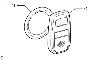
| Result | Proceed to |
|---|---|
| The power source mode changes | A |
| The power source mode does not change | B |
| B |

| GO TO SMART KEY SYSTEM (for Start Function) (Power Source Mode does not Change to ON (IG and ACC)) |
|

| 5. | REGISTRATION |
(a) Using an unregistered electrical key transmitter sub-assembly, perform the additional registration procedure.
Click here

OK:
Additional registration can be completed.
| OK |

| REPLACE ELECTRICAL KEY TRANSMITTER SUB-ASSEMBLY (FIRST REGISTERED KEY WAS DEFECTIVE) |
|

| 6. | REPLACE CERTIFICATION ECU (SMART KEY ECU ASSEMBLY) |
(a) Temporarily replace the certification ECU (smart key ECU assembly) with a new one and register the electrical key transmitter sub-assemblies.
HINT:
-
For replacement.
Click here


-
For registration.
Click here

OK:
All of the electrical key transmitter sub-assemblies could be registered to the new certification ECU (smart key ECU assembly) successfully.
| OK |

| END (CERTIFICATION ECU (SMART KEY ECU ASSEMBLY) WAS DEFECTIVE) |
| NG |

| GO TO OTHER PROBLEM (New Key cannot be Registered) |
| 7. | REREGISTRATION |
(a) Using an unregistered electrical key transmitter sub-assembly, register the ID.
Click here

OK:
The key ID can be registered.
| OK |

| END (ELECTRICAL KEY TRANSMITTER SUB-ASSEMBLY WAS DEFECTIVE) |
| NG |

| REPLACE CERTIFICATION ECU (SMART KEY ECU ASSEMBLY) |
| 8. | READ VALUE USING GTS (OPERATION HISTORY) |
(a) Register the key ID.
Click here

(b) Read the Toyota Prius Vehicle Control History (RoB) according to the display on the GTS.
Body Electrical > Smart Key > Utility| Tester Display |
|---|
| Vehicle Control History (RoB) |
(c) Check the freeze frame data.
| Result | Proceed to |
|---|---|
| [New Key ID Registration Stopped (ID Code Writing Failure)] or [New Key ID Registration Failed (ID Code Writing Failed)] is not displayed on the GTS | A |
| [New Key ID Registration Stopped (ID Code Writing Failure)] or [New Key ID Registration Failed (ID Code Writing Failed)] is displayed on the GTS | B |
| A |

| END (COMMUNICATION ERROR BETWEEN GTS AND Toyota Prius Vehicle) |
| B |

| REPLACE CERTIFICATION ECU (SMART KEY ECU ASSEMBLY)
|


| 9. | READ VALUE USING GTS (Toyota Prius Vehicle SPEED METER) |
(a) Read the Data List according to the display on the GTS.
Body Electrical > Combination Meter > Data List| Tester Display | Measurement Item | Range | Normal Condition | Diagnostic Note |
|---|---|---|---|---|
| Toyota Prius Vehicle Speed Meter | Vehicle speed | Min.: 0, Max.: 255 | Almost same as actual vehicle speed (Speedometer tester) | - |
| Tester Display |
|---|
| Toyota Prius Vehicle Speed Meter |
OK:
[0 km/h (0 mph)] is displayed when the vehicle is stationary.
| OK |

| REPLACE CERTIFICATION ECU (SMART KEY ECU ASSEMBLY)
|


| NG |

| GO TO METER / GAUGE SYSTEM
|


| 10. | CHECK ELECTRICAL KEY TRANSMITTER SUB-ASSEMBLY |
(a) Make sure that a registered electrical key transmitter sub-assembly is being used.
OK:
A registered electrical key transmitter sub-assembly is being used.
| NG |

| USE A REGISTERED ELECTRICAL KEY TRANSMITTER SUB-ASSEMBLY AND PERFORM REREGISTRATION |
|

| 11. | CHECK NUMBER OF REGISTERED ELECTRICAL KEY TRANSMITTER SUB-ASSEMBLIES |
(a) Check the number of registered electrical key transmitter sub-assemblies.
| Result | Proceed to |
|---|---|
| Only one electrical key transmitter sub-assembly is registered | A |
| 2 or more electrical key transmitter sub-assemblies are registered | B |
| A |

| GO TO STEP 13 |
|

| 12. | REREGISTRATION |
(a) Reregister the electrical key transmitter sub-assemblies using different order combinations.
Click here

HINT:
If there are 2 or more electrical key transmitter sub-assemblies, make sure that the number of order combinations is the same as the number of electrical key transmitter sub-assemblies so that each transmitter can be checked first.
Example: When there are 3 registered electrical key transmitter sub-assemblies (A, B and C).| Combination | Order* |
|---|---|
| 1 | A → B → C |
| 2 | B → C→ A |
| 3 | C → A → B |
- *: Except for the first electrical key transmitter sub-assembly, the remaining electrical key transmitter sub-assemblies can be checked in any order.
OK:
"Key Verification: Read Error" is not displayed.
| OK |

| REPLACE ELECTRICAL KEY TRANSMITTER SUB-ASSEMBLY (ELECTRICAL KEY TRANSMITTER SUB-ASSEMBLY HELD WHEN "Key Verification: Read Error" WAS DETECTED WAS DEFECTIVE) |
|

| 13. | REPLACE CERTIFICATION ECU (SMART KEY ECU ASSEMBLY) |
(a) Temporarily replace the certification ECU (smart key ECU assembly) with a new one and register the electrical key transmitter sub-assemblies.
HINT:
-
For replacement.
Click here


-
For registration.
Click here

OK:
All of the electrical key transmitter sub-assemblies could be registered to the new certification ECU (smart key ECU assembly) successfully.
| OK |

| END (CERTIFICATION ECU (SMART KEY ECU ASSEMBLY) WAS DEFECTIVE) |
| NG |

| REPLACE ELECTRICAL KEY TRANSMITTER SUB-ASSEMBLY |
| 14. | CHECK FOR DTC |
(a) Check for DTCs.
Body Electrical > Smart Key > Trouble CodesNOTICE:
If a malfunction occurs, do not remove/install the Toyota Prius vehicle battery before checking for DTCs.
OK:
DTC B278588 is not output.
| NG |

| GO TO DTC B278588 |
|

| 15. | REPLACE CERTIFICATION ECU (SMART KEY ECU ASSEMBLY) |
(a) Temporarily replace the certification ECU (smart key ECU assembly) with a new one and register the electrical key transmitter sub-assemblies.
HINT:
-
For replacement.
Click here


-
For registration.
Click here

OK:
All of the electrical key transmitter sub-assemblies could be registered to the new certification ECU (smart key ECU assembly) successfully.
| OK |

| END (CERTIFICATION ECU (SMART KEY ECU ASSEMBLY) WAS DEFECTIVE) |
| NG |

| REPLACE ID CODE BOX (IMMOBILISER CODE ECU)
|


| 16. | CHECK CERTIFICATION ECU (SMART KEY ECU ASSEMBLY) |
(a) Temporarily replace the certification ECU (smart key ECU assembly) with a new one and register the electrical key transmitter sub-assemblies.
HINT:
-
For replacement.
Click here


-
For registration.
Click here

OK:
All of the electrical key transmitter sub-assemblies could be registered to the new certification ECU (smart key ECU assembly) successfully.
| OK |

| END (CERTIFICATION ECU (SMART KEY ECU ASSEMBLY) WAS DEFECTIVE) |
| NG |

| REPLACE ID CODE BOX (IMMOBILISER CODE ECU)
|


| 17. | REPLACE MAIN BODY ECU (MULTIPLEX NETWORK BODY ECU) |
(a) Temporarily replace the main body ECU (multiplex network body ECU) with a new one and register the electrical key transmitter sub-assemblies.
HINT:
-
For replacement.
Click here


-
For registration.
Click here

OK:
All of the electrical key transmitter sub-assemblies could be registered to the new main body ECU (multiplex network body ECU) successfully.
| OK |

| END (MAIN BODY ECU (MULTIPLEX NETWROK BODY ECU) WAS DEFECTIVE) |
| NG |

| REPLACE CERTIFICATION ECU (SMART KEY ECU ASSEMBLY)
|


New Key Registration Warning Message is not Displayed
DESCRIPTION
If the new key registration warning message is not displayed after an electrical key transmitter sub-assembly has been registered, there may be communication problem between the certification ECU (smart key ECU assembly) and combination meter assembly (meter ECU).
CAUTION / NOTICE / HINT
NOTICE:
-
When using the GTS with the ignition switch off, perform lock and unlock operations using the door control switch of the multiplex network master switch assembly at intervals of 1.5 seconds or less until communication between the GTS and the Toyota Prius vehicle begins, and then select the vehicle model manually.
Then select Model Code "KEY REGIST" under manual mode and enter the following menus: Body Electrical / Smart Key(CAN). While using the GTS, periodically perform lock and unlock operations using the door control switch of the multiplex network master switch assembly at intervals of 1.5 seconds or less to maintain communication between the GTS and the Toyota Prius vehicle.
-
The smart key system (for Start Function) uses the LIN communication system and CAN communication system. Inspect the communication function by following How to Proceed with Troubleshooting. Troubleshoot the smart key system (for Start Function) after confirming that the communication systems are functioning properly.
Click here

-
Before replacing the certification ECU (smart key ECU assembly), refer to Registration.
Click here

- After repair, confirm that no DTCs are output.
- Check that there are no electrical key transmitter sub-assemblies in the Toyota Prius vehicle.
- When replacing the combination meter assembly, always replace it with a new one. If a combination meter assembly which was installed to another vehicle is used, the information stored in it will not match the information from the vehicle and a DTC may be stored.
PROCEDURE
| 1. | CHECK FOR DTC |
(a) Check for DTCs.
Body Electrical > Smart Key > Trouble Codes| Result | Proceed to |
|---|---|
| DTCs are not output | A |
| DTCs are output | B |
| B |

| GO TO DIAGNOSTIC TROUBLE CODE CHART
|


|

| 2. | READ VALUE USING GTS (FL DOOR COURTESY SWITCH STATUS) |
(a) Read the Data List according to the display on the GTS.
Body Electrical > Main Body > Data List| Tester Display | Measurement Item | Range | Normal Condition | Diagnostic Note |
|---|---|---|---|---|
| FL Door Courtesy Switch Status | Front door LH courtesy light switch signal | Close or Open | Close: Front door LH closed Open: Front door LH open | - |
| Tester Display |
|---|
| FL Door Courtesy Switch Status |
| Result | Proceed to |
|---|---|
| On the GTS screen, ON or OFF is displayed accordingly. | A |
| On the GTS screen, ON or OFF is not displayed accordingly. | B |
| B |

| GO TO LIGHTING SYSTEM (Door Courtesy Switch Circuit)
|


|

| 3. | CHECK METER / GAUGE SYSTEM |
(a) With the electrical key transmitter sub-assembly in the Toyota Prius vehicle and all of the doors closed, lock the doors using the entry lock function and check that the warning message is displayed on the multi-information display.
NOTICE:
In order to prevent the electrical key transmitter sub-assembly from being locked inside the vehicle, perform this inspection with the window of a door open.
HINT:
Key lock-in prevention function (Toyota Prius vehicle interior).
Click here

| Result | Proceed to |
|---|---|
| The warning message is displayed on the multi-information display. | A |
| The warning message is not displayed on the multi-information display. | B |
| B |

| REPLACE COMBINATION METER ASSEMBLY |
|

| 4. | ADDITIONAL KEY REGISTRATION |
(a) Clear all of the registered electrical key transmitter sub-assemblies except one and perform registration again.
Click here

|

| 5. | CHECK MULTI-INFORMATION DISPLAY |
(a) With all of the doors closed, lock the doors using the entry lock function.
(b) Unlock the doors using the entry unlock function, open the driver door and check that the warning message is displayed on the multi-information display.
| Result | Proceed to |
|---|---|
| The warning message is displayed on the multi-information display. | A |
| The warning message is not displayed on the multi-information display. | B |
| A |

| END (10 DAYS MAY HAVE ELAPSED SINCE AN ELECTRICAL KEY TRANSMITTER SUB-ASSEMBLY WAS REGISTERED) |
| B |

| REPLACE CERTIFICATION ECU (SMART KEY ECU ASSEMBLY)
|


System Malfunction Message is Displayed on the Multi-information Display
SYSTEM DESCRIPTION
If an abnormal vehicle speed information is detected by the certification ECU (smart key ECU assembly), a system malfunction message is displayed on the multi-information display.
WIRING DIAGRAM
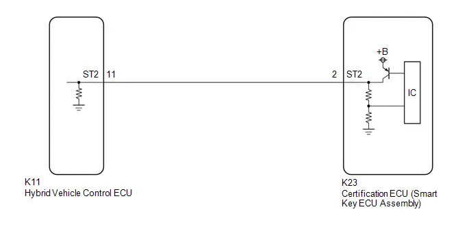
CAUTION / NOTICE / HINT
NOTICE:
-
When using the GTS with the ignition switch off, perform lock and unlock operations using the door control switch of the multiplex network master switch assembly at intervals of 1.5 seconds or less until communication between the GTS and the Toyota Prius vehicle begins, and then select the vehicle model manually.
Then select Model Code "KEY REGIST" under manual mode and enter the following menus: Body Electrical / Smart Key(CAN). While using the GTS, periodically perform lock and unlock operations using the door control switch of the multiplex network master switch assembly at intervals of 1.5 seconds or less to maintain communication between the GTS and the Toyota Prius vehicle.
-
The smart key system (for Start Function) uses the LIN communication system and CAN communication system. Inspect the communication function by following How to Proceed with Troubleshooting. Troubleshoot the smart key system (for Start Function) after confirming that the communication systems are functioning properly.
Click here

-
Before replacing the certification ECU (smart key ECU assembly), refer to Registration.
Click here

PROCEDURE
| 1. | CHECK FOR DTC |
(a) Check for DTCs.
Body Electrical > Smart Key > Trouble Codes Body Electrical > Power Source Control > Trouble Codes| Result | Proceed to |
|---|---|
| DTCs are not output | A |
| DTC is output. | B |
| B |

| GO TO SMART KEY SYSTEM (for Entry Function) (DIAGNOSTIC TROUBLE CODE CHART)
|


|

| 2. | READ VALUE USING GTS (Toyota Prius Vehicle RUNNING CONDITION (LINE)) |
(a) Read the Data List according to the display on the GTS.
Body Electrical > Power Source Control > Data List| Tester Display | Measurement Item | Range | Normal Condition | Diagnostic Note |
|---|---|---|---|---|
| Toyota Prius Vehicle Running Condition (Line) | Vehicle being driven or stopped | Stop or Running | Stop: Vehicle stopped Running: Vehicle being driven at 5 km/h (3 mph) or more | - |
| Tester Display |
|---|
| Toyota Prius Vehicle Running Condition (Line) |
OK:
The GTS display changes correctly in response to the vehicle condition.
| OK |

| REPLACE CERTIFICATION ECU (SMART KEY ECU ASSEMBLY)
|


| NG |

| GO TO ELECTRONICALLY CONTROLLED BRAKE SYSTEM (HOW TO PROCEED WITH TROUBLESHOOTING)
|


Security Indicator Light Does not Blink
DESCRIPTION
- The certification ECU (smart key ECU assembly) blinks the security indicator light (map light assembly) when the immobiliser is set (ignition switch off).
- The certification ECU (smart key ECU assembly) receives the security indicator light signal from the main body ECU (multiplex network body ECU) via CAN communication when the theft deterrent system is in the arming preparation state or alarm sounding state. Then, the certification ECU (smart key ECU assembly) blinks the security indicator light (map light assembly).
WIRING DIAGRAM
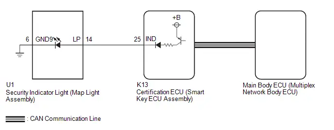
CAUTION / NOTICE / HINT
NOTICE:
-
When using the GTS with the ignition switch off, perform lock and unlock operations using the door control switch of the multiplex network master switch assembly at intervals of 1.5 seconds or less until communication between the GTS and the Toyota Prius vehicle begins, and then select the vehicle model manually.
Then select Model Code "KEY REGIST" under manual mode and enter the following menus: Body Electrical / Smart Key(CAN). While using the GTS, periodically perform lock and unlock operations using the door control switch of the multiplex network master switch assembly at intervals of 1.5 seconds or less to maintain communication between the GTS and the Toyota Prius vehicle.
-
The smart key system (for Start Function) uses the LIN communication system and CAN communication system. Inspect the communication function by following How to Proceed with Troubleshooting. Troubleshoot the smart key system (for Start Function) after confirming that the communication systems are functioning properly.
Click here

-
Before replacing the certification ECU (smart key ECU assembly) or main body ECU (multiplex network body ECU), refer to Registration.
Click here

- Make sure that no DTCs are output. If any DTCs are output, proceed to the Diagnostic Trouble Code Chart.
- After completing repairs, confirm that the problem does not recur.
- After repair, confirm that no DTCs are output by performing "DTC Output Confirmation Operation".
PROCEDURE
| 1. | CHECK FOR DTC |
(a) Check for DTCs.
Body Electrical > Smart Key > Trouble Codes Powertrain > Hybrid Control > Trouble CodesOK:
DTCs are not output.
| NG |

| GO TO DIAGNOSTIC TROUBLE CODE CHART
|


|

| 2. | PERFORM ACTIVE TEST USING GTS (IMMOBILISER INDICATOR) |
(a) Perform the Active Test according to the display on the GTS.
Body Electrical > Smart Key > Active Test| Tester Display | Measurement Item | Control Range | Diagnostic Note |
|---|---|---|---|
| Immobiliser Indicator | Security indicator light | OFF/ON | - |
| Tester Display |
|---|
| Immobiliser Indicator |
OK:
The security indicator light (map light assembly) operates normally.
| NG |

| GO TO STEP 4 |
|

| 3. | CHECK SECURITY INDICATOR LIGHT (MAP LIGHT ASSEMBLY) OPERATION |
(a) When the immobiliser is set, check that the security indicator light (map light assembly) blinks.*1
OK:
The security indicator light (map light assembly) blinks normally.
(b) When the theft deterrent system is in the arming preparation state, check that the security indicator light (map light assembly) illuminates.*2
OK:
The security indicator light (map light assembly) illuminates normally.
| Result | Proceed to |
|---|---|
| *1 is NG (*2 is OK) | A |
| *2 is NG (*1 is OK) | B |
| A |

| REPLACE CERTIFICATION ECU (SMART KEY ECU ASSEMBLY)
|


| B |

| REPLACE MAIN BODY ECU (MULTIPLEX NETWORK BODY ECU)
|


| 4. | CHECK HARNESS AND CONNECTOR (CERTIFICATION ECU (SMART KEY ECU ASSEMBLY) - SECURITY INDICATOR LIGHT (MAP LIGHT ASSEMBLY)) |
(a) Disconnect the K13 certification ECU (smart key ECU assembly) connector.
(b) Disconnect the U1 security indicator light (map light assembly) connector.
(c) Measure the resistance according to the value(s) in the table below.
Standard Resistance:
 Click Location & Routing(K13,U1) Click Connector(K13) Click Connector(U1)
 | Tester Connection | Condition | Specified Condition |
|---|---|---|
| K13-25 (IND) - U1-14 (LP) | Always | Below 1 Ω |
| K13-25 (IND) or U1-14 (LP) - Other terminals and body ground | Always | 10 kΩ or higher |
| NG |

| REPAIR OR REPLACE HARNESS OR CONNECTOR |
|

| 5. | CHECK CERTIFICATION ECU (SMART KEY ECU ASSEMBLY) |
| (a) Connect the K13 certification ECU (smart key ECU assembly) connector. |
|
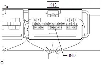
(b) Connect the U1 security indicator light (map light assembly) connector.
(c) Using an oscilloscope, check the waveform.
Measurement Condition:
 Click Location & Routing(K13) Click Connector(K13)
 | Tester Connection | Condition | Specified Condition |
|---|---|---|
| K13-25 (IND) - Body ground | Ignition switch off → ON | Pulse generation → Below 2 V |
| OK |

| REPLACE SECURITY INDICATOR LIGHT (MAP LIGHT ASSEMBLY) |
| NG |

| REPLACE CERTIFICATION ECU (SMART KEY ECU ASSEMBLY)
|


Immobiliser System does not Operate Properly
DESCRIPTION
The immobiliser function compares the ID code that is registered in the certification ECU (smart key ECU assembly) with the ID code of the transponder chip that is embedded in the electrical key transmitter sub-assembly.
WIRING DIAGRAM

CAUTION / NOTICE / HINT
NOTICE:
-
When using the GTS with the ignition switch off, perform lock and unlock operations using the door control switch of the multiplex network master switch assembly at intervals of 1.5 seconds or less until communication between the GTS and the Toyota Prius vehicle begins, and then select the vehicle model manually.
Then select Model Code "KEY REGIST" under manual mode and enter the following menus: Body Electrical / Smart Key(CAN). While using the GTS, periodically perform lock and unlock operations using the door control switch of the multiplex network master switch assembly at intervals of 1.5 seconds or less to maintain communication between the GTS and the Toyota Prius vehicle.
-
The smart key system (for Start Function) uses the LIN communication system and CAN communication system. Inspect the communication function by following How to Proceed with Troubleshooting. Troubleshoot the smart key system (for Start Function) after confirming that the communication systems are functioning properly.
Click here

-
Before replacing the hybrid Toyota Prius vehicle control ECU or certification ECU (smart key ECU assembly), refer to Registration.
Click here

- After repair, confirm that no DTCs are output by performing "DTC Output Confirmation Operation".
HINT:
If an immobiliser function or hybrid control system DTC is output, first perform troubleshooting for the immobiliser function or hybrid control system DTC.
PROCEDURE
| 1. | CHECK FOR DTC |
(a) Check for DTCs.
Body Electrical > Smart Key > Trouble Codes Powertrain > Hybrid Control > Trouble Codes| Result | Proceed to |
|---|---|
| DTCs are not output | A |
| DTCs are output | B |
| B |

| GO TO DIAGNOSTIC TROUBLE CODE CHART
|


|

| 2. | CHECK WHETHER HYBRID CONTROL SYSTEM STARTS |
(a) Check that the hybrid control system starts within 5 seconds of the ignition switch being turned ON (READY).
OK:
Hybrid control system starts normally.
| OK |

| USE SIMULATION METHOD TO CHECK |
|

| 3. | CHECK HYBRID Toyota Prius Vehicle CONTROL ECU (TERMINAL IMI AND IMO) |
(a) Using an oscilloscope, check the waveform.
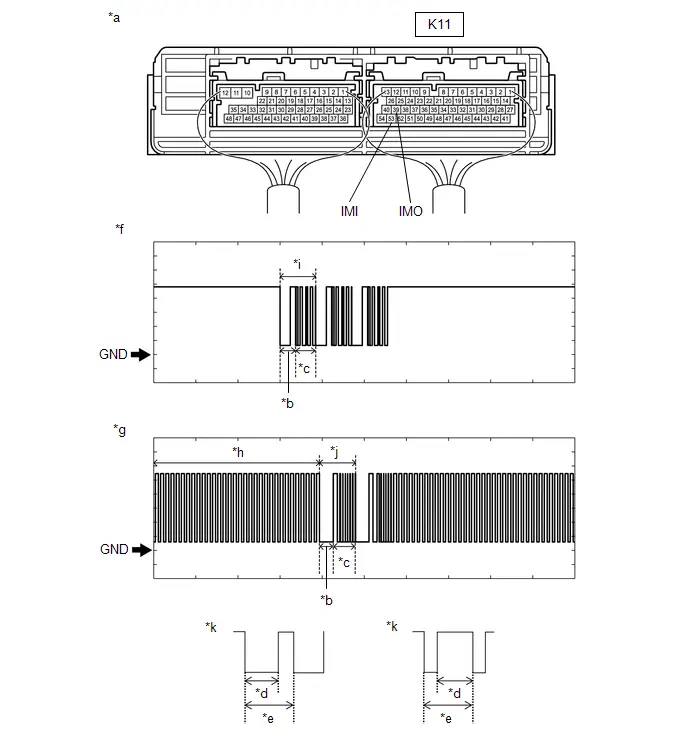
| *a | Component with harness connected (Hybrid Toyota Prius Vehicle Control ECU) | *b | Approximately 160 ms. |
| *c | Approximately 270 ms. | *d | Approximately 40 ms. |
| *e | Approximately 60 ms. | *f | Terminal IMO |
| *g | Terminal IMI | *h | Waveform 1 |
| *i | Waveform 2 | *j | Waveform 3 |
| *k | Waveform 1 (detail) | - | - |
NOTICE:
The waveform shown in the illustration is an example for reference only. Noise, chattering, etc. are not shown.
OK:
 Click Location & Routing(K11) Click Connector(K11)
 | Tester Connection | Condition | Tool Setting | Specified Condition |
|---|---|---|---|
| K11-39 (IMO) - Body ground | Within 3 seconds of hybrid control system start or within 3 seconds of ignition switch turned to ON after auxiliary battery cable disconnected and reconnected | 2 V/DIV., 500 ms./DIV. | Pulse generation (See waveform 2) |
| K11-53 (IMI) - Body ground | Within 3 seconds of hybrid control system start or within 3 seconds of ignition switch turned to ON after auxiliary battery cable disconnected and reconnected | 2 V/DIV., 500 ms./DIV. | Pulse generation (See waveform 1 and 3) |
| Result | Proceed to |
|---|---|
| Normal waveform | A |
| Waveform 1 is not output, or has abnormal wavelength or shape | B |
| Waveform 2 is not output, or has abnormal wavelength or shape | C |
| Waveform 3 is not output, or has abnormal wavelength or shape | D |
| B |

| GO TO STEP 6 |
| C |

| REPLACE HYBRID Toyota Prius Vehicle CONTROL ECU
|


| D |

| GO TO STEP 7 |
|

| 4. | REGISTER ECU COMMUNICATION ID |
(a) Register the ECU communication ID codes.
Click here

|

| 5. | CHECK WHETHER HYBRID CONTROL SYSTEM STARTS |
(a) Check that the hybrid control system starts.
OK:
Hybrid control system starts normally.
| OK |

| END (COMMUNICATION ID REGISTRATION WAS DEFECTIVE) |
| NG |

| REPLACE ID CODE BOX (IMMOBILISER CODE ECU)
|


| 6. | CHECK HARNESS AND CONNECTOR (ID CODE BOX (IMMOBILISER CODE ECU) - HYBRID Toyota Prius Vehicle CONTROL ECU) |
(a) Disconnect the K43 ID code box (immobiliser code ECU) connector.
(b) Disconnect the K11 hybrid vehicle control ECU connector.
(c) Measure the resistance according to the value(s) in the table below.
Standard Resistance:
 Click Location & Routing(K43,K11) Click Connector(K43) Click Connector(K11)
 | Tester Connection | Condition | Specified Condition |
|---|---|---|
| K43-3 (EFII) - K11-39 (IMO) | Always | Below 1 Ω |
| K43-3 (EFII) or K11-39 (IMO) - Other terminals and body ground | Always | 10 kΩ or higher |
| K43-4 (EFIO) - K11-53 (IMI) | Always | Below 1 Ω |
| K43-4 (EFIO) or K11-53 (IMI) - Other terminals and body ground | Always | 10 kΩ or higher |
| OK |

| GO TO STEP 7 |
| NG |

| REPAIR OR REPLACE HARNESS OR CONNECTOR |
| 7. | REPLACE ID CODE BOX (IMMOBILISER CODE ECU) |
(a) Replace the ID code box (immobiliser code ECU) with a new one.
Click here


|

| 8. | REGISTER RECOGNITION CODE |
(a) Register the recognition codes to the ECUs.
Click here

|

| 9. | REGISTER ECU COMMUNICATION ID |
(a) Register the ECU communication ID codes.
Click here

|

| 10. | CHECK WHETHER HYBRID CONTROL SYSTEM STARTS |
(a) Check that the hybrid control system starts.
OK:
Hybrid control system starts normally.
| OK |

| END (ID CODE BOX (IMMOBILISER CODE ECU) WAS DEFECTIVE) |
| NG |

| GO TO HYBRID CONTROL SYSTEM |