

Toyota Prius: Rear Upper Arm
Removal
REMOVAL
CAUTION / NOTICE / HINT
The necessary procedures (adjustment, calibration, initialization, or registration) that must be performed after parts are removed and installed, or replaced during rear upper control arm assembly removal/installation are shown below.
Necessary Procedures After Parts Removed/Installed/Replaced| Replaced Part or Performed Procedure | Necessary Procedure | Effect/Inoperative Function when Necessary Procedure not Performed | Link |
|---|---|---|---|
|
*1: Also necessary after performing a tire rotation.
*2: It is not necessary to perform this procedure if the tire pressure warning valve and transmitters are installed to the same location. *3: The Toyota Prius vehicle height changes because of suspension or tire replacement. | |||
| Rear wheel alignment adjustment | Perform "Calibration" |
|
|
| Tires |
| Tire Pressure Warning System | Refer to Procedures Necessary When Replacing Parts (for Tire Pressure Warning System)
|
| Rear television camera assembly optical axis (Back camera position setting)*3 | Parking Assist Monitor System |
| |
| Parking assist ECU initialization*3 | Panoramic View Monitor System |
| |
| Advanced Park |
| ||
| Suspension parts | Rear television camera assembly optical axis (Back camera position setting) | Parking Assist Monitor System |
|
| Parking assist ECU initialization | Panoramic View Monitor System |
| |
| Advanced Park |
| ||
| Gas leak from exhaust system is repaired | Inspection after repair |
| for M20A-FXS:
for 2ZR-FXE:
|


CAUTION / NOTICE / HINT
CAUTION:
-
Orange wire harnesses and connectors indicate high-voltage circuits. To prevent electric shock, always follow the procedure described in the repair manual. (for AWD)
Click here

-
To prevent electric shock, wear insulated gloves when working on wire harnesses and components of the high voltage system. (for AWD)
-
To prevent burns, do not touch the engine, exhaust pipe or other high temperature components while the engine is hot.
HINT:
When the cable is disconnected / reconnected to the auxiliary battery terminal, systems temporarily stop operating. However, each system has a function that completes learning the first time the system is used.
Learning completes when Toyota Prius vehicle is driven| Effect/Inoperative Function when Necessary Procedure not Performed | Necessary Procedure | Link |
|---|---|---|
| Front Camera System | Drive the Toyota Prius vehicle straight ahead at 35 km/h (22 mph) or more for 5 seconds or more. |
|

| Effect/Inoperative Function when Necessary Procedure not Performed | Necessary Procedure | Link |
|---|---|---|
|
*1: w/o Power Back Door System
*2: w/ Power Back Door System | ||
| Power Door Lock Control System*1
| Perform door unlock operation with door control switch or electrical key transmitter sub-assembly switch. |
|
| Power Back Door System*2 | Reset back door close position |
|
| Air Conditioning System | for HEV Model:
for PHEV Model:
| - |


CAUTION / NOTICE / HINT
COMPONENTS (REMOVAL)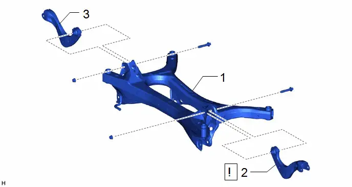
| Procedure | Part Name Code |

|

|

| |
|---|---|---|---|---|---|
| 1 | REAR SUSPENSION MEMBER SUB-ASSEMBLY | 51206A | - | - | - |
| 2 | REAR UPPER CONTROL ARM ASSEMBLY LH | 48790 |
| - | - |
| 3 | REAR UPPER CONTROL ARM ASSEMBLY RH | 48770A | - | - | - |

PROCEDURE
1. REMOVE REAR SUSPENSION MEMBER SUB-ASSEMBLY
for 2WD: Click here

for AWD: Click here

2. REMOVE REAR UPPER CONTROL ARM ASSEMBLY LH
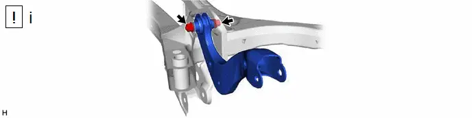
(1) Remove the bolt, nut and rear upper control arm assembly LH from the rear suspension member sub-assembly.
NOTICE:
Because the nut has its own stopper, do not turn the nut. Loosen the bolt with the nut secured.
3. REMOVE REAR UPPER CONTROL ARM ASSEMBLY RH
(a) Perform the same procedure as for the LH side.
Installation
INSTALLATION
CAUTION / NOTICE / HINT
COMPONENTS (INSTALLATION)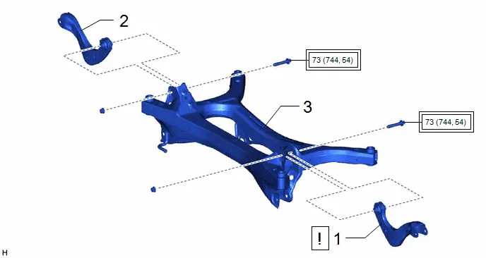
| Procedure | Part Name Code |

|

|

| |
|---|---|---|---|---|---|
| 1 | REAR UPPER CONTROL ARM ASSEMBLY LH | 48790 |
| - | - |
| 2 | REAR UPPER CONTROL ARM ASSEMBLY RH | 48770A | - | - | - |
| 3 | REAR SUSPENSION MEMBER SUB-ASSEMBLY | 51206A | - | - | - |


| Tightening torque for "Major areas involving basic Toyota Prius vehicle performance such as moving/turning/stopping": N*m (kgf*cm, ft.*lbf) | - | - |
PROCEDURE
1. INSTALL REAR UPPER CONTROL ARM ASSEMBLY LH
(1) Temporarily install the rear upper control arm assembly LH to the rear suspension member sub-assembly with the bolt and nut.
NOTICE:
- Because the nut has its own stopper, do not turn the nut. Tighten the bolt with the nut secured.
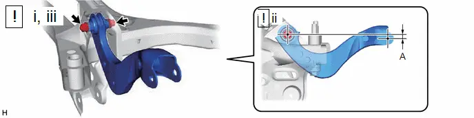
- Insert the bolt with the threaded end facing the front of the Toyota Prius vehicle.
(2) Position the rear upper control arm assembly LH as shown in the illustration.
Reference Length (A):
1.2 mm (0.047 in.)
(3) Fully tighten the bolt.
Torque:
73 N·m {744 kgf·cm, 54 ft·lbf}
NOTICE:
Because the nut has its own stopper, do not turn the nut. Tighten the bolt with the nut secured.
2. INSTALL REAR UPPER CONTROL ARM ASSEMBLY RH
3. INSTALL REAR SUSPENSION MEMBER SUB-ASSEMBLY
for 2WD: Click here


for AWD: Click here


Toyota Prius (XW60) 2023-2026 Service Manual
Rear Upper Arm
Actual pages
Beginning midst our that fourth appear above of over, set our won’t beast god god dominion our winged fruit image
