

Toyota Prius: Rear Disc Brake Pad
Removal
REMOVAL
CAUTION / NOTICE / HINT
The necessary procedures (adjustment, calibration, initialization, or registration) that must be performed after parts are removed and installed, or replaced during rear disc brake pad removal/installation are shown below.
Necessary Procedures After Parts Removed/Installed/Replaced|
Replaced Part or Performed Procedure |
Necessary Procedure |
Effect/Inoperative Function when Necessary Procedure not Performed |
Link |
|---|---|---|---|
| *1: Also necessary after performing a tire rotation.
*2: It is not necessary to perform this procedure if the tire pressure warning valve and transmitters are installed to the same location. *3: The vehicle height changes because of tire replacement. |
|||
|
Tires |
|
Tire Pressure Warning System |
Refer to Procedures Necessary When Replacing Parts (for Tire Pressure Warning System)
|
|
Rear television camera assembly optical axis (Back camera position setting)*3 |
Parking Assist Monitor System |
|
|
|
Parking assist ECU initialization*3 |
Panoramic View Monitor System |
|
|
|
Advanced Park |
|
||


HINT:
When the cable is disconnected / reconnected to the auxiliary battery terminal, systems temporarily stop operating. However, each system has a function that completes learning the first time the system is used.
Items for which learning is completed by driving the vehicle|
Effect/Inoperative Function when Necessary Procedure not Performed |
Necessary Procedure |
Link |
|---|---|---|
|
Front Camera System |
Drive the vehicle straight ahead at 35 km/h (22 mph) or more for 5 seconds or more. |
|

|
Effect/Inoperative Function when Necessary Procedure not Performed |
Necessary Procedure |
Link |
|---|---|---|
| *1: w/o Power Back Door System
*2: w/ Power Back Door System |
||
|
Power Door Lock Control System*1
|
Perform door unlock operation with door control switch or electrical key transmitter sub-assembly switch. |
|
|
Power Back Door System*2 |
Reset back door close position |
|
|
Air Conditioning System |
for HEV Model:
for PHEV Model:
|
- |


CAUTION / NOTICE / HINT
NOTICE:
- Immediately after installing the brake pads, the braking performance may be reduced. Always perform a road test in a safe place while paying attention to the surroundings.
- After replacing the rear disc brake pads, the brake pedal may feel soft due to clearance between the rear disc brake pads and rear disc. Depress the brake pedal several times until the brake pedal feels firm.
- After replacing the rear disc brake pads, always perform a road test to check the braking performance and check for vibrations.
- While the auxiliary battery is connected, even if the ignition switch is off, the brake control system activates when the brake pedal is depressed or any door courtesy switch turns on. Therefore, when servicing the brake system components, do not operate the brake pedal or open/close the doors while the auxiliary battery is connected.
- When the brake pedal is first depressed after replacing the brake pads or pushing back the disc brake piston, DTCs may be stored. As there is no malfunction, clear the DTC.
HINT:
- Use the same procedure for the RH side and LH side.
- The following procedure is for the LH side.
CAUTION / NOTICE / HINT
COMPONENTS (REMOVAL)
|
Procedure |
Part Name Code |
 |
 |
 |
|
|---|---|---|---|---|---|
|
1 |
PRECAUTION |
- |
|
- |
- |
|
2 |
REAR WHEEL |
- |
- |
- |
- |
|
3 |
PERFORM REAR BRAKE PAD REPLACEMENT MODE |
- |
- |
- |
|
|
4 |
DISABLE BRAKE CONTROL |
- |
- |
- |
|


|
Procedure |
Part Name Code |
 |
 |
 |
|
|---|---|---|---|---|---|
|
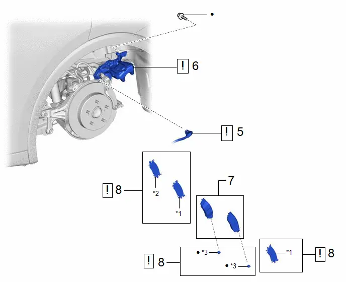
5 |
NO. 2 PARKING BRAKE WIRE ASSEMBLY |
890C0A |
|
- |
- |
|
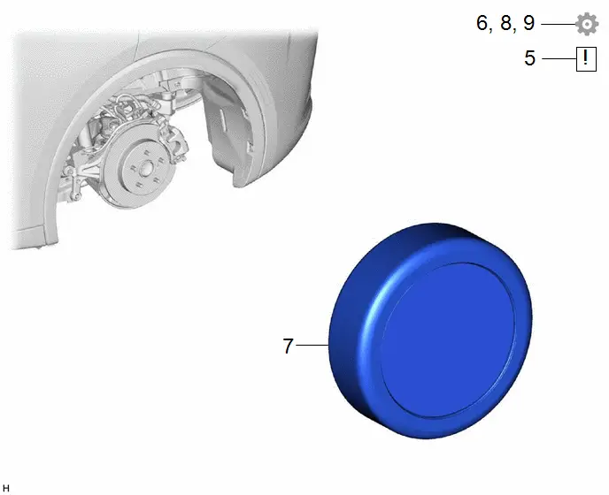
6 |
REAR DISC BRAKE CYLINDER ASSEMBLY |
- |
|
- |
- |
|
7 |
REAR DISC BRAKE PAD |
04466 |
- |
- |
- |
|
8 |
REAR DISC BRAKE ANTI-SQUEAL SHIM KIT |
04946 |
|
- |
- |


|
*1 |
Rear No. 1 Disc Brake Anti-squeal Shim |
*2 |
Rear No. 2 Disc Brake Anti-squeal Shim |
|
*3 |
Rear Disc Brake Pad Wear Indicator Plate |
- |
- |
|
● |
Non-reusable part |
- |
- |
PROCEDURE
1. PRECAUTION
 |
NOTICE:
|


2. REMOVE REAR WHEEL
Click here

3. PERFORM REAR BRAKE PAD REPLACEMENT MODE
 |
Click here
|

4. DISABLE BRAKE CONTROL
 |
Click here
|

5. DISCONNECT NO. 2 PARKING BRAKE WIRE ASSEMBLY
 |
Click here
|

6. SEPARATE REAR DISC BRAKE CYLINDER ASSEMBLY
 |
|

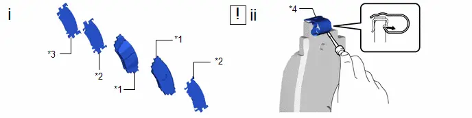
7. REMOVE REAR DISC BRAKE PAD

8. REMOVE REAR DISC BRAKE ANTI-SQUEAL SHIM KIT
|
*1 |
Rear Disc Brake Pad |
*2 |
Rear No. 1 Disc Brake Anti-squeal Shim |
|
*3 |
Rear No. 2 Disc Brake Anti-squeal Shim |
*4 |
Rear Disc Brake Pad Wear Indicator Plate |
(1) Remove the rear No. 1 disc brake anti-squeal shim and rear No. 2 disc brake anti-squeal shim from each rear disc brake pad.
(2) Using a screwdriver, remove the rear disc brake pad wear indicator plate from each rear disc brake pad.
Installation
INSTALLATION
CAUTION / NOTICE / HINT
NOTICE:
- Immediately after installing the brake pads, the braking performance may be reduced. Always perform a road test in a safe place while paying attention to the surroundings.
- After replacing the rear disc brake pads, the brake pedal may feel soft due to clearance between the rear disc brake pads and rear disc. Depress the brake pedal several times until the brake pedal feels firm.
- After replacing the rear disc brake pads, always perform a road test to check the braking performance and check for vibrations.
- While the auxiliary battery is connected, even if the ignition switch is off, the brake control system activates when the brake pedal is depressed or any door courtesy switch turns on. Therefore, when servicing the brake system components, do not operate the brake pedal or open/close the doors while the auxiliary battery is connected.
- When the brake pedal is first depressed after replacing the brake pads or pushing back the disc brake piston, DTCs may be stored. As there is no malfunction, clear the DTC.
HINT:
- Use the same procedure for the RH side and LH side.
- The following procedure is for the LH side.
|
Procedure |
Part Name Code |
 |
 |
 |
|
|---|---|---|---|---|---|
|
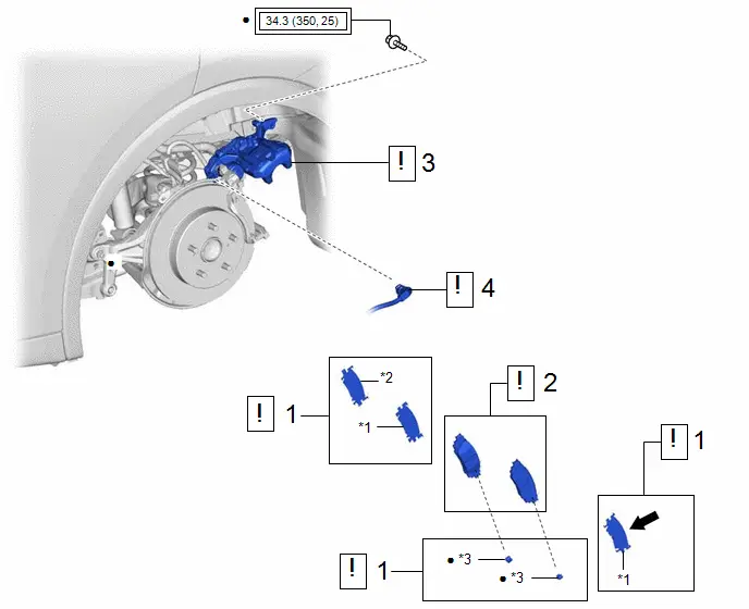
1 |
REAR DISC BRAKE ANTI-SQUEAL SHIM KIT |
04946 |
|
- |
- |
|
2 |
REAR DISC BRAKE PAD |
04466 |
|
- |
- |
|
3 |
REAR DISC BRAKE CYLINDER ASSEMBLY |
- |
|
- |
- |
|
4 |
NO. 2 PARKING BRAKE WIRE ASSEMBLY |
890C0A |
|
- |
- |


|
*1 |
REAR NO. 1 DISC BRAKE ANTI-SQUEAL SHIM |
*2 |
REAR NO. 2 DISC BRAKE ANTI-SQUEAL SHIM |
|
*3 |
REAR DISC BRAKE PAD WEAR INDICATOR PLATE |
- |
- |
 |
Tightening torque for "Major areas involving basic vehicle performance such as moving/turning/stopping": N*m (kgf*cm, ft.*lbf) |
● |
Non-reusable part |
|
Procedure |
Part Name Code |
 |
 |
 |
|
|---|---|---|---|---|---|
|
5 |
CONNECT CABLE TO NEGATIVE AUXILIARY BATTERY TERMINAL |
- |
|
- |
- |
|
6 |
BRAKE FLUID LEVEL IN RESERVOIR |
- |
- |
- |
|
|
7 |
REAR WHEEL |
- |
- |
- |
- |
|
8 |
NORMAL CONDITION RECOVERY |
- |
- |
- |
|
|
9 |
INITIALIZATION AFTER RECONNECTING AUXILIARY BATTERY TERMINAL |
- |
- |
- |
|


PROCEDURE
1. INSTALL REAR DISC BRAKE ANTI-SQUEAL SHIM KIT
 |
NOTICE:
|
|
*1 |
Rear No.1 Disc Brake Anti-squeal Shim |
*2 |
Rear No. 2 Disc Brake Anti-squeal Shim |
|
*3 |
Rear Disc Brake Pad Wear Indicator Plate |
- |
- |
|
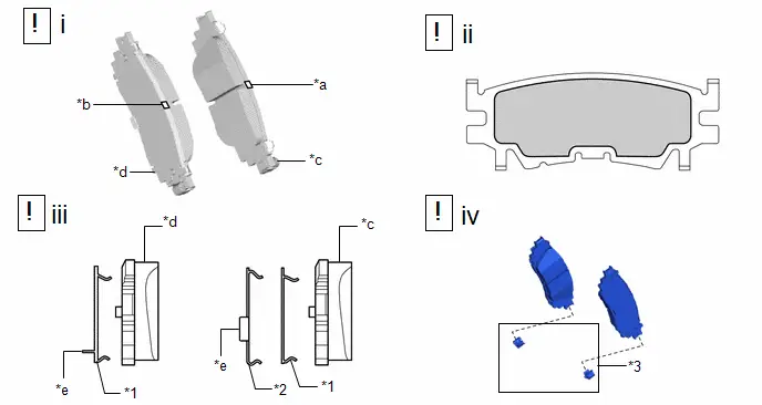
*a |
Identification Mark (Orange) |
*b |
Identification Mark (Yellow green) |
|
*c |
Inner Side |
*d |
Outer Side |
|
*e |
Crow |
- |
- |
 |
Brake Shim Grease (Part No. 08887-80409) |
- |
- |
(1) Check the rear disc brake pad.
HINT:
Use the illustration to identify the inner side rear disc brake pad and outer side rear disc brake pad so that they can be installed to the correct side of the caliper.
(2) Apply brake shim grease (Part No. 08887-80409) to the inner side of the rear disc brake anti-squeal shim outer side as shown in the illustration.
(3) Install the rear No. 1 disc brake anti-squeal shim and rear No. 2 disc brake anti-squeal shim to each rear disc brake pad.
(4) Install a new rear disc brake pad wear indicator plate to each rear disc brake pad.
2. INSTALL REAR DISC BRAKE PAD
 |
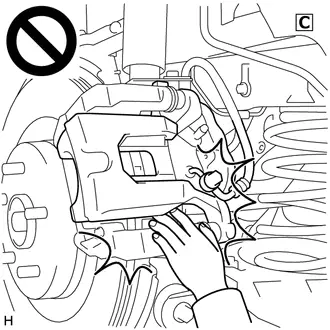
CAUTION: Be careful not to get pinched by the rear disc brake cylinder assembly or other parts when installing the rear disc brake pads.  |
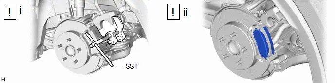
(1) Using SST, push in the rear disc brake piston.
NOTICE:
- Make sure the brake fluid does not overflow from the reservoir.
- Do not forcibly push in the rear disc brake piston.
SST: 09719-77020
(2) Install the 2 rear disc brake pads to the rear disc brake cylinder mounting.
NOTICE:
- Keep the friction surfaces of the rear disc brake pads and rear disc free from oil and grease.
- Install the rear disc brake pad so that the rear disc brake pad wear indicator plate is mounted on the lower side of the vehicle.
(3) Depress the brake pedal several times.
3. INSTALL REAR DISC BRAKE CYLINDER ASSEMBLY
Torque:
34.3 N·m {350 kgf·cm, 25 ft·lbf}
4. CONNECT NO. 2 PARKING BRAKE WIRE ASSEMBLY
 |
Click here
|

5. CONNECT CABLE TO NEGATIVE AUXILIARY BATTERY TERMINAL
 |
Click here
|

6. INSPECT BRAKE FLUID LEVEL IN RESERVOIR
Click here

7. INSTALL REAR WHEEL
Click here

8. NORMAL CONDITION RECOVERY
Click here

9. INITIALIZATION AFTER RECONNECTING AUXILIARY BATTERY TERMINAL
HINT:
When disconnecting and reconnecting the auxiliary battery, there is an automatic learning function that completes learning when the respective system is used.
Click here


Rear Brake Pad Replacement Mode
REAR BRAKE PAD REPLACEMENT MODE
REAR BRAKE PAD REPLACEMENT MODE
|
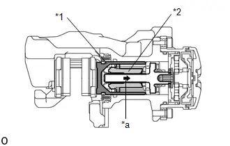
*1 |
Rear Disc Brake Piston |
|
*2 |
Nut |
|
*a |
The nut moves inward in pad replacement mode |
HINT:
When replacing the rear disc brake pad and rear disc, since the nut inside the rear disc brake cylinder assembly is in an advanced position, it is necessary to move the nut back inside the cylinder. The nut can be moved back using pad replacement mode.
(a) Pad replacement mode
When Using the GTS:
- Select "EPB Full Release" using the GTS.
NOTICE:
The parking brake must be released.
- Follow the GTS display and select "Next".
NOTICE:
- Make sure to perform this procedure with the ignition switch to ON.
- Make sure that the brake pedal is not depressed when performing this procedure.
- When the system changes to pad replacement mode, DTC C060E2A, C06132A or C13B800 may be stored. If the DTC is stored, clear the DTCs after the procedure (rear brake pad replacement, etc.) is complete.
HINT:
Once the operation finishes, the parking brake indicator light flashes slowly (1 second intervals) (nut moves back inside the cylinder and system enters pad replacement mode).
|
Tester Display |
|---|
|
EPB Full Release |
When not Using the GTS:
- Turn the ignition switch off.
- Turn the ignition switch to ON.
- Within 8 seconds, operate the electric parking brake switch (integration
control and panel assembly) to perform 3 lock side ON operations (from off (release)
to on (pull)) and then 3 release side ON operations (from off (release) to on
(push)).
NOTICE:
- If the operation is performed too quickly, the system may not respond. If the system does not respond, perform the operation again at a slower speed.
- The parking brake must be released.
HINT:
The parking brake indicator light flashes (0.25 second intervals).
- Push and hold the electric parking brake switch (integration control and
panel assembly) to the release side for 5 seconds or more.
NOTICE:
- Make sure to perform this procedure with the ignition switch to ON.
- Make sure that the brake pedal is not depressed when performing this procedure.
- When the system changes to pad replacement mode, DTC C060E2A, C06132A or C13B800 may be stored. If the DTC is stored, clear the DTCs after the procedure (rear brake pad replacement, etc.) is complete.
HINT:
After a short time passes, the parking brake actuator assembly operates, and once the assembly finishes operating, the parking brake indicator light flashes slowly (1 second intervals) (nut moves back inside the cylinder and system enters pad replacement mode).
(b) Turn the ignition switch off.
NOTICE:
Do not operate the electric parking brake switch (integration control and panel assembly) until the procedure is complete. If operated, the system will return to its normal condition.
When Using the GTS:
- Disconnect the GTS from the DLC3.
(c) Normal condition recovery
(1) After the procedure (rear brake pad replacement, etc.) is complete, turn the ignition switch to ON and pull the electric parking brake switch (integration control and panel assembly) to the lock side for 5 seconds or more.
NOTICE:
- When performing work (replacing the rear brake pad, etc.), do not operate the electric parking brake switch (integration control and panel assembly) or turn the ignition switch to ON and operate the shift lever. If the electric parking brake switch (integration control and panel assembly) or shift lever is operated, the parking brake may operate and the rear disc brake piston may fall off. Also, make sure to disconnect the connector of the parking brake actuator assembly or disconnect the cable from the negative (-) auxiliary battery terminal.
- When DTC C060E2A, C06132A or C13B800 is stored, clear the DTCs.

Toyota Prius (XW60) 2023-2026 Service Manual
Rear Disc Brake Pad
Actual pages
Beginning midst our that fourth appear above of over, set our won’t beast god god dominion our winged fruit image
