

Toyota Prius: Rear Crankshaft Oil Seal
Removal
REMOVAL
CAUTION / NOTICE / HINT
The necessary procedures (adjustment, calibration, initialization or registration) that must be performed after parts are removed and installed, or replaced during rear crankshaft oil removal/installation are shown below.
Necessary Procedures After Parts Removed/Installed/Replaced| Replaced Part or Performed Procedure | Necessary Procedure | Effect/Inoperative Function when Necessary Procedure not Performed | Link |
|---|---|---|---|
|
*: Even when not replacing the part, it is necessary to perform the specified necessary procedures after installation.
*1: Also necessary after performing a tire rotation. *2: It is not necessary to perform this procedure if the tire pressure warning valve and transmitters are installed to the same location. | |||
| Replacement of ECM | Update ECU security key | Toyota Prius Vehicle Control History (RoB) are stored |
|
| ECU configuration | - |
| |
| Perform Toyota Prius Vehicle Identification Number (VIN) registration | DTC is output |
| |
| Inspection after repair |
|
|
| Replacement of inverter with converter assembly | ECU configuration | - |
|
| Resolver learning |
|
| |
| Replacement of hybrid vehicle transaxle assembly |
|
|
|
| Suspension parts | Rear television camera assembly optical axis (Back camera position setting) | Parking Assist Monitor System |
|
| Parking assist ECU initialization | Panoramic View Monitor System |
| |
| Advanced Park |
| ||
| Tires |
| Tire Pressure Warning System | Refer to Procedures Necessary When Replacing Parts (for Tire Pressure Warning System) table below |
| Rear television camera assembly optical axis (Back camera position setting) | Parking Assist Monitor System |
| |
| Parking assist ECU initialization | Panoramic View Monitor System |
| |
| Advanced Park |
| ||
| Replacement of front bumper assembly* | Front television camera view adjustment | Panoramic View Monitor System |
|
| Advanced Park |
| ||


HINT:
When the cable is disconnected / reconnected to the auxiliary battery terminal, systems temporarily stop operating. However, each system has a function that completes learning the first time the system is used.
-
Learning completes when Toyota Prius vehicle is driven
Effect/Inoperative Function When Necessary Procedures are not Performed
Necessary Procedures
Link
Front Camera System
Drive the Toyota Prius vehicle straight ahead at 35 km/h (22 mph) or more for 5 seconds or more.

-
Learning completes when vehicle is operated normally
Effect/Inoperative Function When Necessary Procedures are not Performed
Necessary Procedures
Link
*1: w/o Power Back Door System *2: w/ Power Back Door System
Power Door Lock Control System*1
- Back door opener
Perform door unlock operation with door control switch or electrical key transmitter sub-assembly switch.

Power Back Door System*2
Reset back door close position

Air Conditioning System
After the ignition switch is turned to ON, the servo motor standard position is recognized.
-
CAUTION / NOTICE / HINT
COMPONENTS (REMOVAL)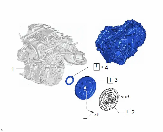
| Procedure | Part Name Code |

|

|

| |
|---|---|---|---|---|---|
| 1 | ENGINE ASSEMBLY | - | - | - | - |
| 2 | TRANSMISSION INPUT DAMPER ASSEMBLY | 31270 |
| - | - |
| 3 | FLYWHEEL SUB-ASSEMBLY | 13405 |
| - | - |
| 4 | REAR ENGINE OIL SEAL | 11401L |
| - | - |


| ● | Non-reusable part | ★ | Precoated part |
PROCEDURE
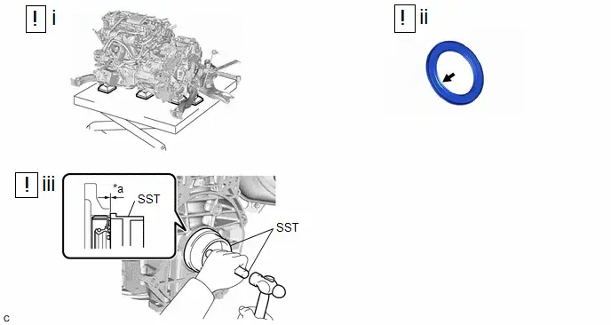
1. REMOVE ENGINE ASSEMBLY
Click here

2. REMOVE TRANSMISSION INPUT DAMPER ASSEMBLY
(1) Using height adjustment attachments and plate lift attachments, place the engine assembly on a flat level surface.
NOTICE:
- Using height adjustment attachments and plate lift attachments, keep the engine assembly horizontal.
- To prevent the oil pan sub-assembly from deforming, do not place any attachments under the oil pan sub-assembly of the engine assembly.
- Using an engine sling device and engine lift, secure the engine assembly before servicing.
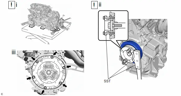
(2) Using SST, hold the crankshaft pulley.
SST: 09213-58014
91551-80840
SST: 09330-00021
(3) Remove the 6 bolts and transmission input damper assembly from the flywheel sub-assembly.
3. REMOVE FLYWHEEL SUB-ASSEMBLY
(1) Using SST, hold the crankshaft pulley.
SST: 09213-58014
91551-80840
SST: 09330-00021
(2) Remove the 8 bolts and flywheel sub-assembly from the crankshaft.
4. REMOVE REAR ENGINE OIL SEAL

| *a | Cut Position | - | - |
(1) Using a knife, cut through the lip of the rear engine oil seal.
(2) Using a screwdriver with its tip wrapped with protective tape, pry out the rear engine oil seal.
NOTICE:
Be careful not to damage the crankshaft.
Installation
INSTALLATION
CAUTION / NOTICE / HINT
COMPONENTS (INSTALLATION)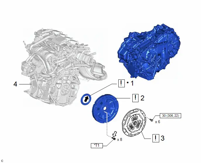
| Procedure | Part Name Code |

|

|

| |
|---|---|---|---|---|---|
| 1 | REAR ENGINE OIL SEAL | 11401L |
| - | - |
| 2 | FLYWHEEL SUB-ASSEMBLY | 13405 |
| - | - |
| 3 | TRANSMISSION INPUT DAMPER ASSEMBLY | 31270 |
| - | - |
| 4 | ENGINE ASSEMBLY | - | - | - | - |


| N*m (kgf*cm, ft.*lbf): Specified torque | ● | Non-reusable part |

| MP grease |

| Adhesive 1324 |
| ★ | Precoated part | - | - |
| *T1 | 1st: 49 (500, 36) 2nd: Turn 90° | - | - |
PROCEDURE
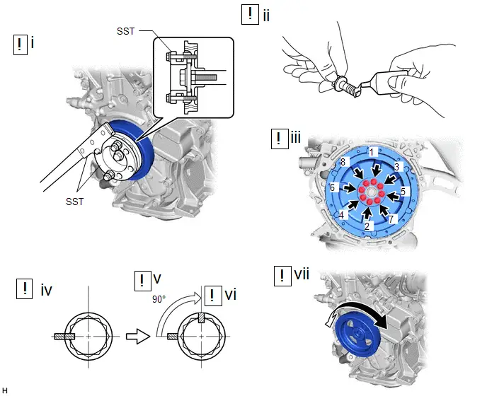
1. INSTALL REAR ENGINE OIL SEAL
| *a | Tap in Depth | - | - |
(1) Using height adjustment attachments and plate lift attachments, place the engine assembly on a flat level surface.
NOTICE:
- Using height adjustment attachments and plate lift attachments, keep the engine assembly horizontal.
- To prevent the oil pan sub-assembly from deforming, do not place any attachments under the oil pan sub-assembly of the engine assembly.
- Using an engine sling device and engine lift, secure the engine assembly before servicing.
(2) Apply MP grease to the lip of a new rear engine oil seal.
NOTICE:
Keep the lip free from foreign matter.
(3) Using SST and a hammer, tap in the rear engine oil seal.
SST: 09223-15030
SST: 09950-70010
09951-07100
Rear Engine Oil Seal Tap in Depth:
-1.0 to 1.0 mm (-0.0394 to 0.0394 in.)
NOTICE:
- Keep the lip free from foreign matter.
- Do not tap in the rear engine oil seal at an angle.
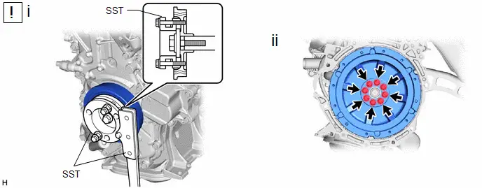
2. INSTALL FLYWHEEL SUB-ASSEMBLY

| Paint Mark | - | - |
(1) Using SST, hold the crankshaft pulley.
SST: 09213-58014
91551-80840
SST: 09330-00021
(2) Apply adhesive to the 8 bolts.
Adhesive:
Toyota Genuine Adhesive 1324, Three Bond 1324 or equivalent
(3) Install and uniformly tighten the 8 bolts in several steps in the order shown in the illustration.
Torque:
49 N·m {500 kgf·cm, 36 ft·lbf}
NOTICE:
Do not start the engine for at least 1 hour after installing the flywheel sub-assembly.
(4) Mark each bolt head with paint as shown in the illustration.
(5) Tighten the 8 bolts by 90° in the same order.
(6) Check that the paint marks are now at a 90° angle.
(7) Check that the crankshaft turns smoothly.
3. INSTALL TRANSMISSION INPUT DAMPER ASSEMBLY
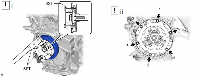
(1) Using SST, hold the crankshaft pulley.
SST: 09213-58014
91551-80840
SST: 09330-00021
(2) Install the transmission input damper assembly to the flywheel sub-assembly with the 6 bolts. Uniformly tighten the 6 bolts in the order shown in the illustration.
Torque:
30 N·m {306 kgf·cm, 22 ft·lbf}
NOTICE:
- Make sure that there is no oil on the transmission input damper assembly or flywheel sub-assembly.
- Make sure to install the transmission input damper assembly in the correct direction.
- Do not allow grease to contact the splines of the transmission input damper assembly or the input shaft.
4. INSTALL ENGINE ASSEMBLY
Click here


Toyota Prius (XW60) 2023-2026 Service Manual
Rear Crankshaft Oil Seal
Actual pages
Beginning midst our that fourth appear above of over, set our won’t beast god god dominion our winged fruit image
