

Toyota Prius: Low Pressure Magnetic Valve
Removal
REMOVAL
CAUTION / NOTICE / HINT
The necessary procedures (adjustment, calibration, initialization or registration) that must be performed after parts are removed and installed, or replaced during No. 3 magnet valve assembly removal/installation are shown below.
Necessary Procedures After Parts Removed/Installed/Replaced| Replaced Part or Performed Procedure | Necessary Procedures | Effect/Inoperative Function When Necessary Procedures are not Performed | Link |
|---|---|---|---|
| *: Even when not replacing the part, it is necessary to perform the specified necessary procedures after installation. | |||
| Front bumper assembly* | Front television camera view adjustment | Panoramic View Monitor System |
|
| Advanced Park |
| ||


CAUTION / NOTICE / HINT
COMPONENTS (REMOVAL)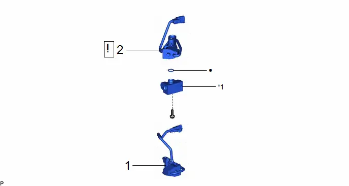
| Procedure | Part Name Code |

|

|

| |
|---|---|---|---|---|---|
| 1 | NO. 2 MAGNET VALVE ASSEMBLY | 88690N | - | - | - |
| 2 | NO. 3 MAGNET VALVE ASSEMBLY | 88F90C |
| - | - |

| *1 | CONNECTOR TUBE | - | - |
| ● | Non-reusable part | - | - |
PROCEDURE
1. REMOVE NO. 2 MAGNET VALVE ASSEMBLY
Click here

2. REMOVE NO. 3 MAGNET VALVE ASSEMBLY
(1) Remove the bolt and No. 3 magnet valve assembly from the connector tube.
(2) Remove the O-ring from the connector tube.
NOTICE:
Seal the openings of the disconnected parts using vinyl tape to prevent entry of moisture and foreign matter.
Inspection
INSPECTION
PROCEDURE
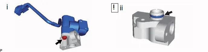
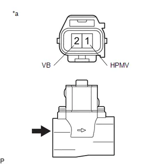
1. INSPECT NO. 3 MAGNET VALVE ASSEMBLY
| (a) Apply auxiliary battery voltage to the terminals of the connector, and check the No. 3 magnet valve assembly operates. OK:
If the result is not as specified, replace the No. 3 magnet valve assembly. |
|
Installation
INSTALLATION
CAUTION / NOTICE / HINT
COMPONENTS (INSTALLATION)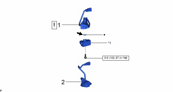
| Procedure | Part Name Code |

|

|

| |
|---|---|---|---|---|---|
| 1 | NO. 3 MAGNET VALVE ASSEMBLY | 88F90C |
| - | - |
| 2 | NO. 2 MAGNET VALVE ASSEMBLY | 88690N | - | - | - |

| *1 | CONNECTOR TUBE | - | - |

| N*m (kgf*cm, ft.*lbf): Specified torque | ● | Non-reusable part |

| Compressor oil ND-OIL 11 or equivalent | - | - |
PROCEDURE
1. INSTALL NO. 3 MAGNET VALVE ASSEMBLY
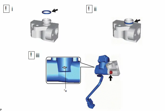
| *a | Reference Point | - | - |
(1) Remove the vinyl tape from the connector tube and No. 3 magnet valve assembly, and sufficiently apply compressor oil to a new O-ring and the fitting surface of the connector tube.
Compressor Oil:
ND-OIL 11 or equivalent
(2) Install the O-ring to the connector tube.
NOTICE:
Keep the O-ring and O-ring fitting surface free from foreign matter.
(3) Install the No. 3 magnet valve assembly to the connector tube with the bolt.
NOTICE:
Make sure to install the No. 3 magnet valve assembly with the arrow facing the direction shown in the illustration.
Torque:
9.8 N·m {100 kgf·cm, 87 in·lbf}
2. INSTALL NO. 2 MAGNET VALVE ASSEMBLY
Click here


Toyota Prius (XW60) 2023-2026 Service Manual
Actual pages
Beginning midst our that fourth appear above of over, set our won’t beast god god dominion our winged fruit image
