

Toyota Prius: Garage Door Opener System (for Digital Inner Mirror)
- Precaution
- Parts Location
- System Diagram
- System Description
- How To Proceed With Troubleshooting
- Registration
- Terminals Of Ecu
- Dtc Check / Clear
- Data List / Active Test
- Diagnostic Trouble Code Chart
- On-vehicle Inspection
- Lost Communication with TCM Missing Message (U010187,U014087,U029387)
Precaution
PRECAUTION
PRECAUTIONS FOR DISCONNECTING CABLE FROM NEGATIVE (-) AUXILIARY BATTERY TERMINAL
NOTICE:
After the ignition switch is turned off, there may be a waiting time before disconnecting the negative (-) auxiliary battery terminal.
Click here

HINT:
When disconnecting and reconnecting the auxiliary battery, there is an automatic learning function that completes learning when the respective system is used.
Click here


Parts Location
PARTS LOCATION
ILLUSTRATION
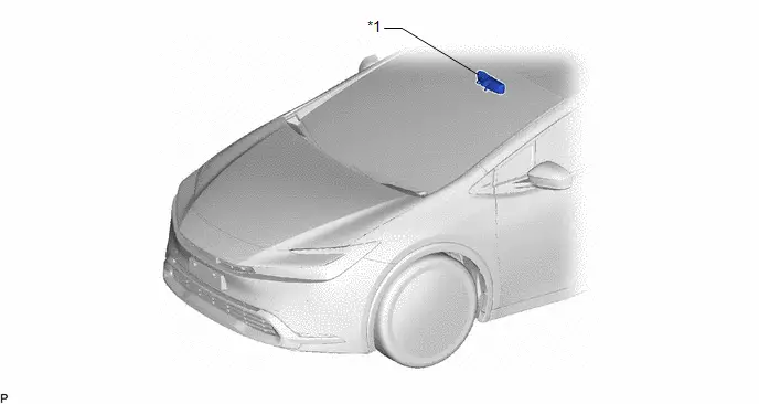
| *1 | INNER REAR VIEW MIRROR ASSEMBLY - GARAGE DOOR OPENER | - | - |
ILLUSTRATION
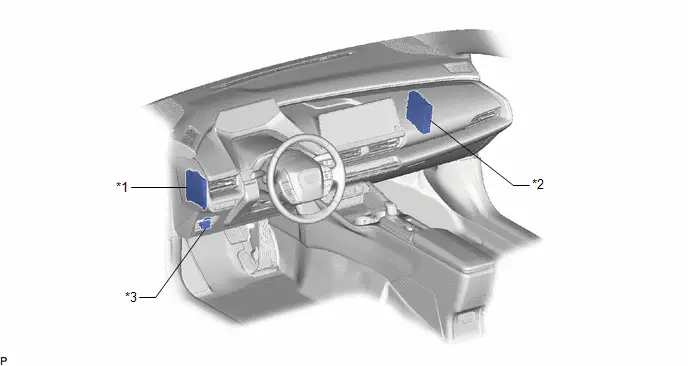
| *1 | MAIN BODY ECU (MULTIPLEX NETWORK BODY ECU) | *2 | HYBRID Toyota Prius Vehicle CONTROL ECU |
| *3 | DLC3 | - | - |
System Diagram
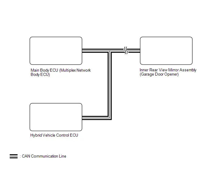
SYSTEM DIAGRAM
System Description
SYSTEM DESCRIPTION
DESCRIPTION
(a) A maximum of 3 kinds of transmitter code based systems (example: garage doors, gates and entry gates) can be registered with the vehicle garage door opener. After registration, the vehicle garage door opener can mimic the signal of the transmitter systems and the original transmitters of each transmitter system are not needed.
How To Proceed With Troubleshooting
CAUTION / NOTICE / HINT
HINT:
- Use the following procedure to troubleshoot the garage door opener system.
- *: Use the GTS.
PROCEDURE
| 1. | Toyota Prius Vehicle BROUGHT TO WORKSHOP |
|

| 2. | CUSTOMER PROBLEM ANALYSIS |
(a) Interview the customer to confirm the problem.
Click here

|

| 3. | INSPECT BATTERY VOLTAGE |
(a) Measure the auxiliary battery voltage with the ignition switch off.
Standard voltage:
11 to 14 V
HINT:
If the voltage is below 11 V, recharge or replace the auxiliary battery before proceeding to the next step.
(b) Check the fuses and relays.
(c) Check the connector connections and terminals to make sure that there are no abnormalities such as loose connections, deformation, etc.
|

| 4. | CHECK COMMUNICATION FUNCTION OF CAN COMMUNICATION SYSTEM* |
(a) Using the GTS, check for CAN communication system DTCs.
Click here

| Result | Proceed to |
|---|---|
| CAN DTCs are not output | A |
| CAN DTCs are output | B |
| B |

| GO TO CAN COMMUNICATION SYSTEM |
|

| 5. | CHECK FOR DTC* |
(a) Clear for DTCs.
Body Electrical > Digital Rear-View Mirror > Clear DTCs(b) Check for DTCs.
Body Electrical > Digital Rear-View Mirror > Trouble Codes| Result | Proceed to |
|---|---|
| DTCs are not output | A |
| Garage Door Opener system DTCs are output | B |
| B |

| GO TO DIAGNOSTIC TROUBLE CODE CHART |
|

| 6. | OVERALL ANALYSIS AND TROUBLESHOOTING* |
(a) Terminals of ECU
Click here

(b) On-Toyota Prius Vehicle Inspection
Click here

|

| 7. | REPAIR OR REPLACE |
|

| 8. | CONFIRMATION TEST |
| NEXT |

| END |
Registration
REGISTRATION
PROCEDURE
1. REGISTER TRANSMITTER CODE
HINT:
- The vehicle garage door opener records transmitter codes for systems such as garage doors, gates, entry gates, door locks, home lighting systems, security systems or other transmitter code based systems.
- The garage door opener is built into the inner rear view mirror assembly. If replacing the inner rear view mirror assembly, transmitter codes for any systems previously registered in the garage door opener must be re-registered.
(a) Re-registration of codes in the garage door opener system (registration mode).
CAUTION:
Do not perform transmitter code registration for a system if people or objects are near the system. When registering transmitter codes for a system, injury or damage can occur because the system may open, close, unlock or otherwise operate.
NOTICE:
- Before transmitter code registration, confirm that all the electrical systems (headlight, blower motor, rear defogger, etc.) are turned off and no key is in the Toyota Prius vehicle.
-
The garage door opener cannot be used with systems that:
(1) Were manufactured before April 1, 1982.
(2) Do not meet federal safety standards (for example, garage doors without a jam protection function).
HINT:
- A maximum of 3 transmitter codes can be registered with the garage door opener system. It is possible to register 1 handheld transmitter code (original transmitter) for each of the 3 garage door opener system switches.
- Disconnecting the Toyota Prius vehicle battery will not clear the transmitter codes registered in the garage door opener system.
- An attempt to overwrite a previously registered code may fail. In this case, the previously registered transmitter code will not be cleared.
- To successfully program the garage door opener system, it may be necessary to replace the handheld transmitter battery before programming.
- If registration is performed when the battery level of the transmitter is low, the transmitted radio waves may be too weak and registration may not complete properly.
| (1) Step 1: Select a garage door opener ("HomeLink") switch for transmitter code registration and check that the ("HomeLink") indicator light flashes. HINT: Perform step 3 within 60 seconds of step 1, or the indicator light will stop flashing and programming will not be able to be completed. |
|
| (2) Step 2: Point the remote control transmitter for the device at the inner rear view mirror assembly, 2.5 to 7.5 cm (1.0 to 3.0 in.) from the garage door opener ("HomeLink") switches. HINT: Keep the ("HomeLink") indicator light in view while programming. |
|
(3) Step 3:
for USA:
except Entry Gate
Press and hold the handheld transmitter button until the ("HomeLink") indicator light changes from slowly flashing (orange) to rapidly flashing (green) (rolling code) or continuously lit (green) (fixed code), then release the handheld transmitter button.
for Entry Gate
Repeatedly press and release the handheld transmitter button at 2 second intervals until the ("HomeLink") indicator light changes from slowly flashing (orange) to rapidly flashing (green) (rolling code) or continuously lit (green) (fixed code).
for Canada:
Repeatedly press and release the handheld transmitter button at 2 second intervals until the ("HomeLink") indicator light changes from slowly flashing (orange) to rapidly flashing (green) (rolling code) or continuously lit (green) (fixed code).
(4) Step 4:
Test the ("HomeLink") operation by pressing the newly programmed switch and observing the indicator light.
HINT:
- Device with fixed code: if the indicator light is solid and continuous, programming has been completed and the device should activate when the garage door opener ("HomeLink") switch is pressed and released.
- Device with rolling code: if the indicator light flashes rapidly, the garage door opener motor (or other device) is equipped with a rolling code. Complete the programming process by firmly pressing and holding the programmed garage door opener ("HomeLink") switch for 2 seconds and then release the handheld transmitter button.
- If the garage door or other device does not operate, proceed to "Programming a rolling code system".
(5) If the transmitter code registration was successful, the ("HomeLink") indicator light of the garage door opener flashes (green) at a cycle of 10 Hz (rapidly). If no malfunction occurs, release both the garage door opener ("HomeLink") switch and handheld transmitter button.
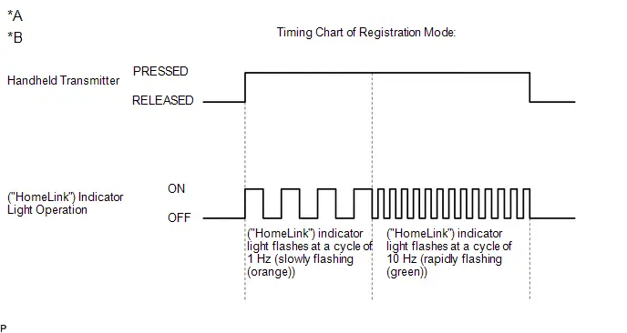
| *A | for USA | *B | except Entry Gate |
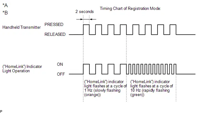
| *A | for USA | *B | for Entry Gate |
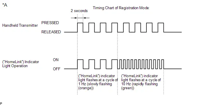
| *A | for Canada | - | - |
HINT:
-
If transmitter code registration fails:
(1) The battery in the handheld transmitter may be weak or needs to be replaced.
(2) The handheld transmitter and opener device to be registered may not be compatible with the garage door opener.
-
Some transmitter signals stop after 1 to 2 seconds. For these types of transmitters:
(1) Press and hold one of the garage door opener ("HomeLink") switches.
(2) Press and release the handheld transmitter button every 2 seconds. Check if the transmitter code was successfully registered.
- After entering the garage door opener registration mode, transmitter code registration must be completed within 60 seconds. If 60 seconds elapse, the garage door opener will enter low power mode (refer to "Low Power Mode" below).
(6) Repeat the steps above to program another device for any of the remaining garage door opener ("HomeLink") switches.
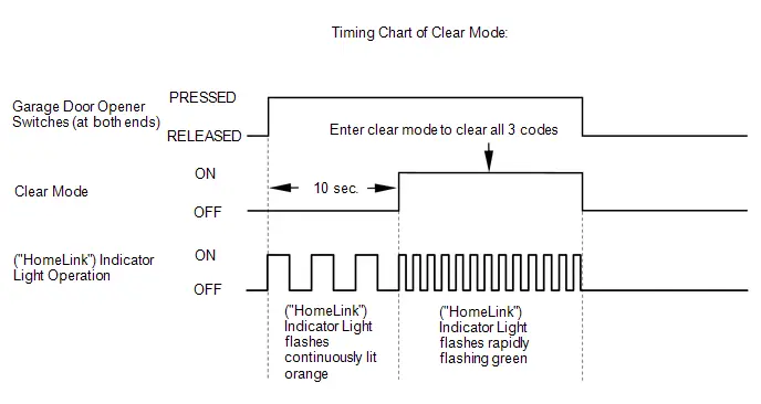
(b) Clearing transmitter codes in the garage door opener system (clear mode).
HINT:
All 3 registered transmitter codes will be cleared. No option exists for only erasing one transmitter code.
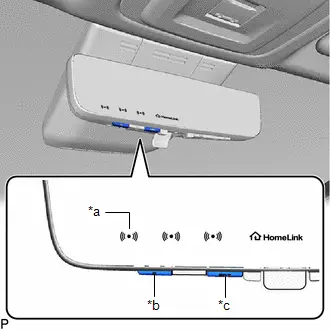
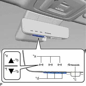
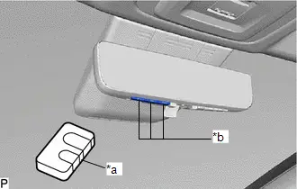
| *a | ("HomeLink") Indicator Light |
| *b | Garage Door Opener ("HomeLink") Switch 1 |
| *c | Garage Door Opener ("HomeLink") Switch 3 |
(1) Press and hold the garage door opener ("HomeLink") switches 1 and 3 for 10 seconds until the ("HomeLink") indicator light changes from continuously lit orange to rapidly flashing green.
(c) Low power mode:
(1) If a garage door opener ("HomeLink") switch is held for 60 seconds or more, the garage door opener will enter low power mode to reduce power consumption. When the garage door opener has entered low power mode, the ("HomeLink") indicator light turns off.
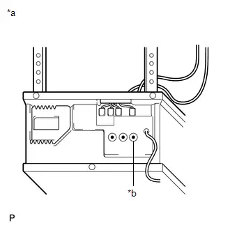
2. ROLLING CODE SYSTEMS
| (a) If the handheld transmitter for the opener device (customer's garage door) being programmed uses a rolling code, it may be necessary to "train" the garage door opener device. HINT:
(1) Locate the training button on the opener device. (2) Press the training button. (3) Within 30 seconds, press and release the programmed garage door opener ("HomeLink") switch twice. Some opener devices may require the garage door opener ("HomeLink") switch to be pressed 3 times. HINT: The Toyota Prius vehicle garage door opener system should now operate the opener device. Opener device refers to a device such as a ceiling mounted garage door opener, which is located at the customer's residence. It is necessary to read the instructions for the customer's opener device, to allow the above procedure to be performed safely and successfully. The customer should be aware that performing this procedure will result in a lowered level of security for the customer's opener device. |
|
Terminals Of Ecu
TERMINALS OF ECU
INNER REAR VIEW MIRROR ASSEMBLY (GARAGE DOOR OPENER)

(a) Disconnect the U12 inner rear view mirror assembly connector.
(b) Measure the voltage and resistance according to the value(s) in the table below.
HINT:
Measure the values on the wire harness side with the connector disconnected.
| Terminal No. (Symbol) | Terminal Description | Condition | Specified Condition |
|---|---|---|---|
| U12-1 (IG) - Body ground | IG power supply | Ignition switch off | Below 1 V |
| Ignition switch ON | 11 to 14 V | ||
| U12-6 ( B) - Body ground | Auxiliary battery power supply | Ignition switch off | 11 to 14 V |
| U12-2 (E) - Body ground | Ground | Always | Below 1 Ω |
Dtc Check / Clear
DTC CHECK / CLEAR
ALL READINESS
HINT:
- With "All Readiness", you can check whether or not the DTC judgment has been completed by using the GTS.
- You should check "All Readiness" after simulating malfunction symptoms or for validation after finishing repairs.
(a) Connect the GTS to the DLC3.
(b) Turn the ignition switch to ON
(c) Turn the GTS on.
(d) Clear the DTCs even if no DTCs are stored. Enter the following menus: Body Electrical / Digital Rear-View Mirror / Trouble Codes.
Body Electrical > Digital Rear-View Mirror > Clear DTCs(e) Turn the ignition switch off.
(f) Turn the ignition switch to ON.
(g) Check that the power supply voltage of the inner rear view mirror assembly is 10 V or more, then turn the ignition switch to ON and wait for 20 seconds or more.
(h) Enter the following menus: Body Electrical / Digital Rear-View Mirror / Utility.
Body Electrical > Digital Rear-View Mirror > Utility| Tester Display |
|---|
| All Readiness |
(i) Input the DTC to be confirmed.
(j) Check the DTC judgment result.
| GTS Display | Description |
|---|---|
| Normal |
|
| Abnormal |
|
| Incomplete |
|
| N/A |
|
If the judgment result shows Incomplete or N/A, check that the power supply voltage of the inner rear view mirror assembly is 10 V or more, then turn the ignition switch to ON and wait for 20 seconds or more, then run the DTC judgement.
Data List / Active Test
DATA LIST / ACTIVE TEST
DATA LIST
NOTICE:
In the table below, the values listed under "Normal Condition" are reference values. Do not depend solely on these reference values when deciding whether a part is faulty or not.
HINT:
Using the GTS to read the Data List allows the values or states of switches, sensors, actuators and other items to be read without removing any parts. This non-intrusive inspection can be very useful because intermittent conditions or signals may be discovered before parts or wiring is disturbed. Reading the Data List information early in troubleshooting is one way to save diagnostic time.
(a) Enter the following menus: Body Electrical / Digital Rear-View Mirror / Data List.
(b) Read the Data List according to the display on the GTS.
Body Electrical > Digital Rear-View Mirror > Data List| Tester Display | Measurement Item | Range | Normal Condition | Diagnostic Note |
|---|---|---|---|---|
| Total Distance Traveled | Current total driving distance | 0 to 999999 | Equivalent to the actual total driving distance | - |
| Total Distance Traveled - Unit | Unit of total distance traveled | km or mile | - | - |
Diagnostic Trouble Code Chart
DIAGNOSTIC TROUBLE CODE CHART
Garage Door Opener System| DTC No. | Detection Item | DTC Output from | Priority | Link |
|---|---|---|---|---|
| U010187 | Lost Communication with TCM Missing Message | Digital Rear-View Mirror | B |
|
| U014087 | Lost Communication with Body Control Module Missing Message | Digital Rear-View Mirror | B |
|
| U029387 | Lost Communication with Hybrid/EV Powertrain Control Module Missing Message | Digital Rear-View Mirror | B |
|


On-vehicle Inspection
ON-VEHICLE INSPECTION
PROCEDURE
1. INSPECT GARAGE DOOR OPENER
| (a) Press each garage door opener ("HomeLink") switch and check that the ("HomeLink") indicator light turns on. If one or more of the garage door opener ("HomeLink") switches does not turn on the ("HomeLink") indicator light, check the condition of the fuse and wire harness. If the wire of the fuse is broken or the wire harness is malfunctioning repair or replace it. If not, replace the inner rear view mirror assembly (garage door opener). HINT: Click here
|
|


2. INSPECT GARAGE DOOR OPENER REGISTRATION AND TRANSMITTING
HINT:
Use the "HomeLink" tester and a tester transmitter for this test. First clear the customer transmitter codes, and then register the tester transmitter code.
Click here

(a) Check if the tester transmitter code was successfully registered.
HINT:
- Any garage door opener ("HomeLink") switch can be pressed.
-
If the code cannot be registered, replace the inner rear view mirror assembly (garage door opener).
Click here

| (b) Apply battery voltage to the "HomeLink" tester as shown in the illustration. |
|
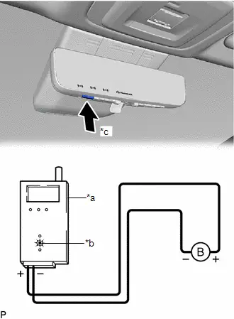
(c) Press a garage door opener ("HomeLink") switch. Check if the red LED of the "HomeLink" tester illuminates.
HINT:
If the red LED does not illuminate, replace the inner rear view mirror assembly (garage door opener).
Click here

(d) When the inspection is complete, register the customer transmitter code(s) again.
HINT:
- Registration of the customer transmitter code(s) may not be possible in the service facility if the customer's transmitters are not available or if any of the buttons are used for rolling code-type systems.
- Refer to the Owner's Manual for additional information about registration (programming) of transmitter codes.
Lost Communication with TCM Missing Message (U010187,U014087,U029387)
DESCRIPTION
- U010187: The inner rear view mirror assembly receives signals from the hybrid vehicle control ECU via CAN communication.
- U014087: The inner rear view mirror assembly receives signals from the main body ECU (multiplex network body ECU) via CAN communication.
- U029387: The inner rear view mirror assembly receives signals from the hybrid Toyota Prius vehicle control ECU via CAN communication.
| DTC No. | Detection Item | DTC Detection Condition | Trouble Area | DTC Output from | Priority |
|---|---|---|---|---|---|
| U010187 | Lost Communication with TCM Missing Message | No communication between inner rear view mirror assembly and hybrid Toyota Prius vehicle control ECU for 10 seconds or more. (1-trip detection logic*) |
| Digital Rear-View Mirror | B |
| U014087 | Lost Communication with Body Control Module Missing Message | No communication between inner rear view mirror assembly and main body ECU (multiplex network body ECU) for 10 seconds or more. (1-trip detection logic*) |
| Digital Rear-View Mirror | B |
| U029387 | Lost Communication with Hybrid/EV Powertrain Control Module Missing Message | No communication between inner rear view mirror assembly and hybrid Toyota Prius vehicle control ECU for 10 seconds or more. (1-trip detection logic*) |
| Digital Rear-View Mirror | B |
- *: Only detected while a malfunction is present and the ignition switch is ON.
HINT:
After repairs have been completed, clear the DTCs and then check that the Toyota Prius vehicle has returned to normal by performing "All Readiness" using the GTS.
Click here

- Check that the power supply voltage of the inner rear view mirror assembly is 10 V or more.
- Turn the ignition switch to ON and wait for 20 seconds or more.
PROCEDURE
| 1. | CLEAR DTC |
(a) Clear the DTCs.
Body Electrical > Digital Rear-View Mirror > Clear DTCs
|

| 2. | CHECK FOR DTC |
(a) Check if CAN communication DTCs are output.
Body Electrical > Digital Rear-View Mirror > Trouble CodesOK:
DTC U010187, U014087 and U029387 are not output
| Result | Proceed to |
|---|---|
| DTCs are not output | A |
| U010187, U014087 or U029387 is output | B |
HINT:
- If CAN communication system malfunction DTCs are output, they may also be output for other systems.
- If the CAN communication system has been inspected and repaired in other systems, the DTC will not be output when rechecking for DTCs.
-
If the DTC is output frequently, duplicate the conditions that cause the problem symptoms and perform the check again, even though the DTC was not output when rechecking for DTCs.
Click here

| A |

| USE SIMULATION METHOD TO CHECK |
| B |

| GO TO CAN COMMUNICATION SYSTEM |

Toyota Prius (XW60) 2023-2026 Service Manual
Garage Door Opener System (for Digital Inner Mirror)
- Precaution
- Parts Location
- System Diagram
- System Description
- How To Proceed With Troubleshooting
- Registration
- Terminals Of Ecu
- Dtc Check / Clear
- Data List / Active Test
- Diagnostic Trouble Code Chart
- On-vehicle Inspection
- Lost Communication with TCM Missing Message (U010187,U014087,U029387)
Actual pages
Beginning midst our that fourth appear above of over, set our won’t beast god god dominion our winged fruit image
