

Toyota Prius: Fuel Tank
Removal
REMOVAL
CAUTION / NOTICE / HINT
The necessary procedures (adjustment, calibration, initialization or registration) that must be performed after parts are removed and installed, or replaced during fuel tank sub-assembly removal/installation are shown below.
Necessary Procedures After Parts Removed/Installed/Replaced| Replaced Part or Performed Procedure | Necessary Procedure | Effect/Inoperative Function when Necessary Procedure not Performed | Link |
|---|---|---|---|
|
*1: Also necessary after performing a tire rotation.
*2: It is not necessary to perform this procedure if the tire pressure warning valve and transmitters are installed to the same location. *3: The Toyota Prius vehicle height changes because of tire replacement. | |||
| Tires |
| Tire Pressure Warning System | Refer to Procedures Necessary When Replacing Parts (for Tire Pressure Warning System)
|
| Rear television camera assembly optical axis (Back camera position setting)*3 | Parking Assist Monitor System |
| |
| Parking assist ECU initialization*3 | Panoramic View Monitor System |
| |
| Advanced Park |
| ||
| Gas leak from exhaust system is repaired | Inspection after repair |
|
|


CAUTION:
-
Never perform work on fuel system components near any possible ignition sources.
- Vaporized fuel could ignite, resulting in a serious accident.
-
Do not perform work on fuel system components without first disconnecting the cable from the negative (-) auxiliary battery terminal.
- Sparks could cause vaporized fuel to ignite, resulting in a serious accident.
-
The fuel tank sub-assembly is very heavy. Be sure to follow the procedure described in the repair manual, or the fuel tank sub-assembly may fall off the engine lifter.

NOTICE:
After the ignition switch is turned off, there may be a waiting time before disconnecting the negative (-) auxiliary battery terminal.
Click here

HINT:
When the cable is disconnected / reconnected to the auxiliary battery terminal, systems temporarily stop operating. However, each system has a function that completes learning the first time the system is used.
Learning completes when Toyota Prius vehicle is driven| Effect/Inoperative Function when Necessary Procedure not Performed | Necessary Procedure | Link |
|---|---|---|
| Front Camera System | Drive the Toyota Prius vehicle straight ahead at 35 km/h (22 mph) or more for 5 seconds or more. |
|

| Effect/Inoperative Function when Necessary Procedure not Performed | Necessary Procedure | Link |
|---|---|---|
|
*1: w/o Power Back Door System
*2: w/ Power Back Door System | ||
| Power Door Lock Control System*1
| Perform door unlock operation with door control switch or electrical key transmitter sub-assembly switch. |
|
| Power Back Door System*2 | Reset back door close position |
|
| Air Conditioning System | After the ignition switch is turned to ON, the servo motor standard position is recognized. | - |


CAUTION / NOTICE / HINT
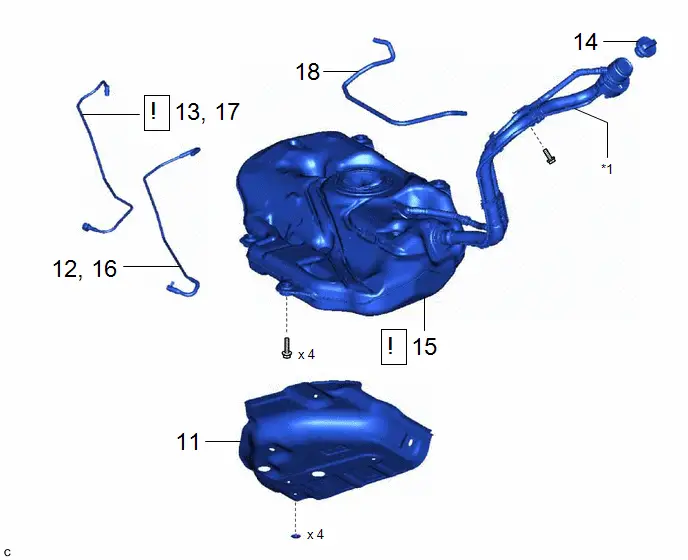
COMPONENTS (REMOVAL)
| Procedure | Part Name Code |

|

|

| |
|---|---|---|---|---|---|
| 1 | PRECAUTION | - |
| - | - |
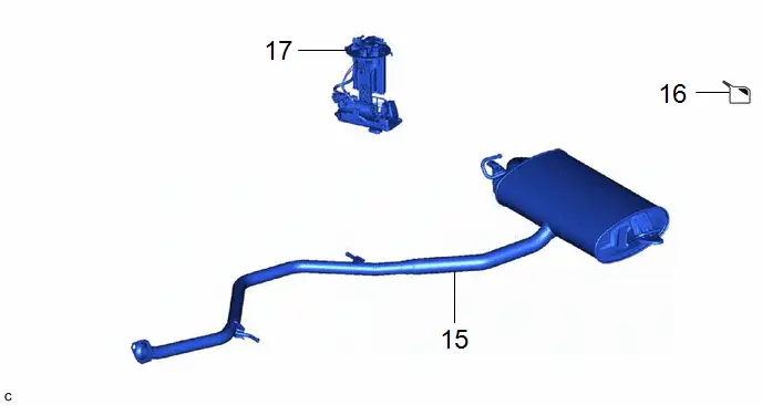
| 2 | FUEL SUCTION TUBE WITH PUMP AND GAUGE ASSEMBLY | 77020A | - | - | - |
| 3 | DRAIN FUEL | - | - |
| - |
| 4 | TAIL EXHAUST PIPE ASSEMBLY | 17430 | - | - | - |


| Procedure | Part Name Code |

|

|

| |
|---|---|---|---|---|---|
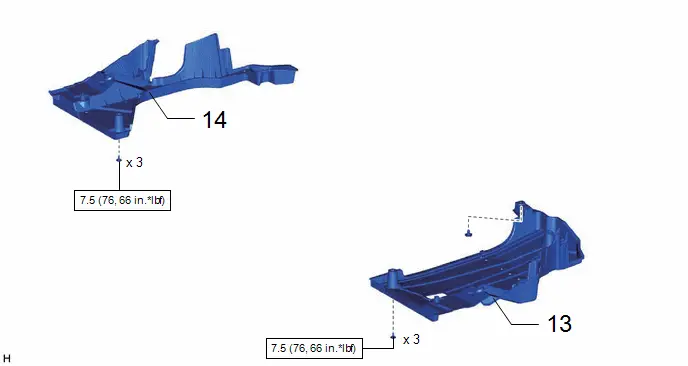
| 5 | REAR FLOOR SIDE MEMBER COVER LH | 57628E | - | - | - |
| 6 | REAR FLOOR SIDE MEMBER COVER RH | 57627G | - | - | - |
| Procedure | Part Name Code |

|

|

| |
|---|---|---|---|---|---|
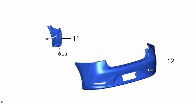
| 7 | REAR BUMPER ASSEMBLY | - | - | - | - |
| 8 | REAR BUMPER SIDE SEAL LH | 52592 | - | - | - |

| Procedure | Part Name Code |

|

|

| |
|---|---|---|---|---|---|
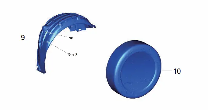
| 9 | REAR WHEEL | - | - | - | - |
| 10 | REAR WHEEL HOUSE LINER LH | 65638 | - | - | - |
| Procedure | Part Name Code |

|

|

| |
|---|---|---|---|---|---|
| 11 | NO. 1 FUEL TANK PROTECTOR | 77641A | - | - | - |
| 12 | DISCONNECT NO. 1 FUEL EVAPORATION TUBE SUB-ASSEMBLY | 77026A | - | - | - |
| 13 | DISCONNECT FUEL TANK MAIN TUBE SUB-ASSEMBLY | 77209F |
| - | - |
| 14 | FUEL TANK CAP ASSEMBLY | 77310A | - | - | - |
| 15 | FUEL TANK SUB-ASSEMBLY | 77100U |
| - | - |
| 16 | REMOVE NO. 1 FUEL EVAPORATION TUBE SUB-ASSEMBLY | 77026A | - | - | - |
| 17 | REMOVE FUEL TANK MAIN TUBE SUB-ASSEMBLY | 77209F | - | - | - |
| 18 | CHARCOAL CANISTER OUTLET HOSE | 77754B | - | - | - |


| *1 | FUEL TANK FILLER PIPE ASSEMBLY | - | - |
PROCEDURE
1. PRECAUTION
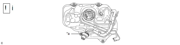
| *a | Cord | - | - |
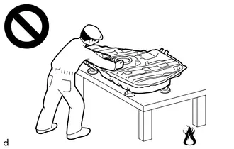
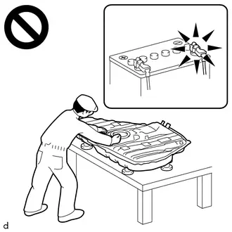
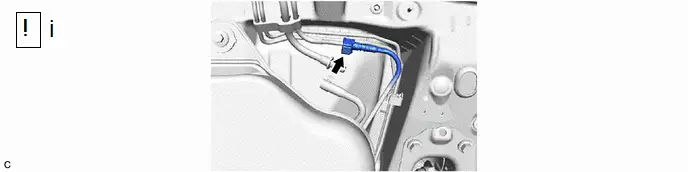
(1) When removing and storing the fuel tank sub-assembly, arrange the fuel tank filler pipe assembly as shown in the illustration, and secure the fuel tank sub-assembly using a cord or similar.
NOTICE:
Depending on the arrangement of the fuel tank filler pipe assembly during storage, the fuel tank filler pipe assembly and rear suspension may interfere and cause fuel leakage.
2. REMOVE FUEL SUCTION TUBE WITH PUMP AND GAUGE ASSEMBLY
Click here

3. DRAIN FUEL
4. REMOVE TAIL EXHAUST PIPE ASSEMBLY
Click here

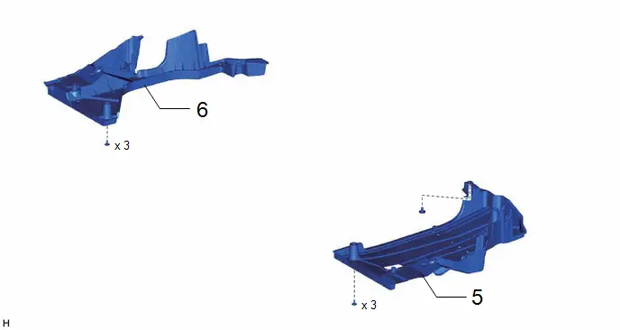
5. REMOVE REAR FLOOR SIDE MEMBER COVER LH
Click here


6. REMOVE REAR FLOOR SIDE MEMBER COVER RH
Click here


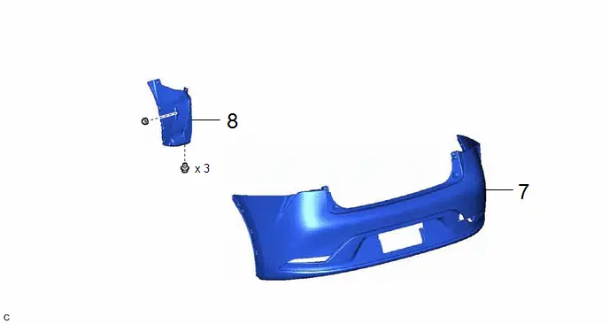
7. REMOVE REAR BUMPER ASSEMBLY
Click here

8. REMOVE REAR BUMPER SIDE SEAL LH
Click here

9. REMOVE REAR WHEEL
Click here

10. REMOVE REAR WHEEL HOUSE LINER LH

11. REMOVE NO. 1 FUEL TANK PROTECTOR

12. DISCONNECT NO. 1 FUEL EVAPORATION TUBE SUB-ASSEMBLY

13. DISCONNECT FUEL TANK MAIN TUBE SUB-ASSEMBLY

(1) Disconnect the fuel tank main tube sub-assembly from the fuel pipe.
Click here

14. REMOVE FUEL TANK CAP ASSEMBLY

15. REMOVE FUEL TANK SUB-ASSEMBLY

| CAUTION: The fuel tank sub-assembly is very heavy. Be sure to follow the procedure described in the repair manual, or the fuel tank sub-assembly may fall off the engine lifter. 
|
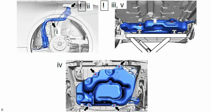
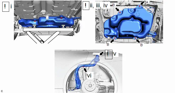
(1) Remove the bolt.
(2) Disengage the locations shown in the illustration, and disconnect the fuel tank filler pipe assembly from the Toyota Prius vehicle body.
(3) Support the fuel tank sub-assembly using an engine lifter.
HINT:
Using height adjustment attachments and plate lift attachments, keep the fuel tank sub-assembly horizontal.
(4) Remove the 4 bolts.
(5) Lower the engine lifter to remove the fuel tank sub-assembly.
NOTICE:
- Be careful not to drop the fuel tank sub-assembly.
- When removing the fuel tank sub-assembly, tilt it slightly to prevent it from interfering with the surrounding parts.
16. REMOVE NO. 1 FUEL EVAPORATION TUBE SUB-ASSEMBLY

17. REMOVE FUEL TANK MAIN TUBE SUB-ASSEMBLY

18. REMOVE CHARCOAL CANISTER OUTLET HOSE

Installation
INSTALLATION
CAUTION / NOTICE / HINT
COMPONENTS (INSTALLATION)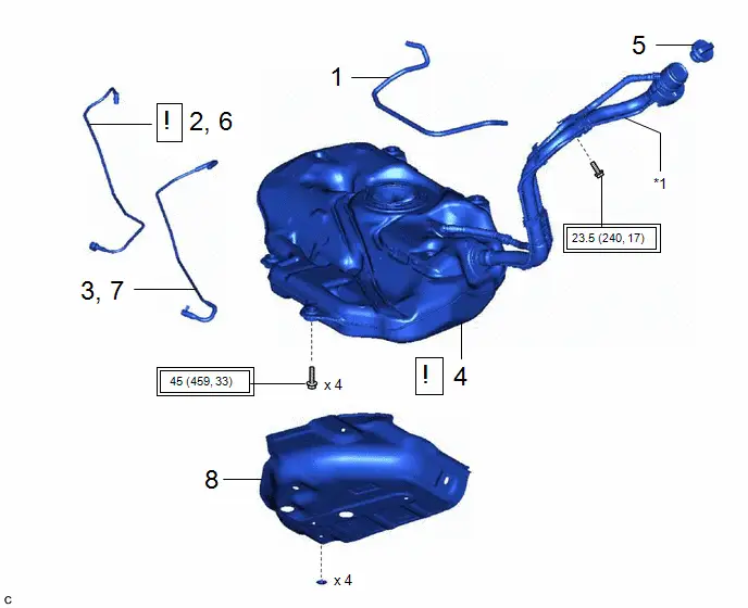
| Procedure | Part Name Code |

|

|

| |
|---|---|---|---|---|---|
| 1 | CHARCOAL CANISTER OUTLET HOSE | 77754B | - | - | - |
| 2 | INSTALL FUEL TANK MAIN TUBE SUB-ASSEMBLY | 77209F | - | - | - |
| 3 | INSTALL NO. 1 FUEL EVAPORATION TUBE SUB-ASSEMBLY | 77026A | - | - | - |
| 4 | FUEL TANK SUB-ASSEMBLY | 77100U |
| - | - |
| 5 | FUEL TANK CAP ASSEMBLY | 77310A | - | - | - |
| 6 | CONNECT FUEL TANK MAIN TUBE SUB-ASSEMBLY | 77209F |
| - | - |
| 7 | CONNECT NO. 1 FUEL EVAPORATION TUBE SUB-ASSEMBLY | 77026A | - | - | - |
| 8 | NO. 1 FUEL TANK PROTECTOR | 77641A | - | - | - |


| *1 | FUEL TANK FILLER PIPE ASSEMBLY | - | - |

| Tightening torque for "Major areas involving basic Toyota Prius vehicle performance such as moving/turning/stopping": N*m (kgf*cm, ft.*lbf) | - | - |
| Procedure | Part Name Code |

|

|

| |
|---|---|---|---|---|---|
| 9 | REAR WHEEL HOUSE LINER LH | 65638 | - | - | - |
| 10 | REAR WHEEL | - | - | - | - |
| Procedure | Part Name Code |

|

|

| |
|---|---|---|---|---|---|
| 11 | REAR BUMPER SIDE SEAL LH | 52592 | - | - | - |
| 12 | REAR BUMPER ASSEMBLY | - | - | - | - |
| Procedure | Part Name Code |

|

|

| |
|---|---|---|---|---|---|
| 13 | REAR FLOOR SIDE MEMBER COVER LH | 57628E | - | - | - |
| 14 | REAR FLOOR SIDE MEMBER COVER RH | 57627G | - | - | - |

| N*m (kgf*cm, ft.*lbf): Specified torque | - | - |
| Procedure | Part Name Code |

|

|

| |
|---|---|---|---|---|---|
| 15 | TAIL EXHAUST PIPE ASSEMBLY | 17430 | - | - | - |
| 16 | ADD FUEL | - | - |
| - |
| 17 | FUEL SUCTION TUBE WITH PUMP AND GAUGE ASSEMBLY | 77020A | - | - | - |

PROCEDURE
1. INSTALL CHARCOAL CANISTER OUTLET HOSE
2. INSTALL FUEL TANK MAIN TUBE SUB-ASSEMBLY
3. INSTALL NO. 1 FUEL EVAPORATION TUBE SUB-ASSEMBLY
4. INSTALL FUEL TANK SUB-ASSEMBLY

| CAUTION: The fuel tank sub-assembly is very heavy. Be sure to follow the procedure described in the repair manual, or the fuel tank sub-assembly may fall off the engine lifter. 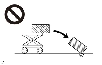
|
(1) Set the fuel tank sub-assembly on an engine lifter.
NOTICE:
Using height adjustment attachments and plate lift attachments, keep the fuel tank sub-assembly horizontal.
(2) Using the engine lifter, slowly raise the fuel tank sub-assembly, and then temporarily install the fuel tank sub-assembly with the 4 bolts.
NOTICE:
- Be careful not to drop the fuel tank sub-assembly.
- When installing the fuel tank sub-assembly, tilt it slightly to prevent it from interfering with the surrounding parts.
(3) Tighten the bolt (A).
Torque:
45 N·m {459 kgf·cm, 33 ft·lbf}
(4) Tighten the 3 bolts (B).
Torque:
45 N·m {459 kgf·cm, 33 ft·lbf}
(5) Engage the locations shown in the illustration, and connect the fuel tank filler pipe assembly to the Toyota Prius vehicle body.
(6) Install the bolt.
Torque:
23.5 N·m {240 kgf·cm, 17 ft·lbf}
5. INSTALL FUEL TANK CAP ASSEMBLY
6. CONNECT FUEL TANK MAIN TUBE SUB-ASSEMBLY
(1) Connect the fuel tank main tube sub-assembly to the fuel pipe.
Click here

7. CONNECT NO. 1 FUEL EVAPORATION TUBE SUB-ASSEMBLY
8. INSTALL NO. 1 FUEL TANK PROTECTOR
9. INSTALL REAR WHEEL HOUSE LINER LH
10. INSTALL REAR WHEEL
Click here

11. INSTALL REAR BUMPER SIDE SEAL LH
12. INSTALL REAR BUMPER ASSEMBLY
Click here

13. INSTALL REAR FLOOR SIDE MEMBER COVER LH
14. INSTALL REAR FLOOR SIDE MEMBER COVER RH
15. INSTALL TAIL EXHAUST PIPE ASSEMBLY
Click here

16. ADD FUEL
17. INSTALL FUEL SUCTION TUBE WITH PUMP AND GAUGE ASSEMBLY
Click here


Toyota Prius (XW60) 2023-2026 Service Manual
Fuel Tank
Actual pages
Beginning midst our that fourth appear above of over, set our won’t beast god god dominion our winged fruit image
