

Toyota Prius: Front Marker Light
Removal
REMOVAL
CAUTION / NOTICE / HINT
The necessary procedures (adjustment, calibration, initialization or registration) that must be performed after parts are removed and installed, or replaced during front marker light assembly removal/installation are shown below.
Necessary Procedures After Parts Removed/Installed/Replaced| Replaced Part or Performed Procedure | Necessary Procedures | Effect/Inoperative Function When Necessary Procedures are not Performed | Link |
|---|---|---|---|
| *1: Even when not replacing the part, it is necessary to perform the specified necessary procedures after installation. | |||
| Front bumper assembly*1 | Front television camera view adjustment | Panoramic View Monitor System |
|
| Advanced Park |
| ||
| Replacement or removal and installation of 2 or more parts:
| Television camera view adjustment | Panoramic View Monitor System |
|


CAUTION / NOTICE / HINT
HINT:
- Use the same procedure for the RH side and LH side.
- The following procedure is for the LH side.
CAUTION / NOTICE / HINT
COMPONENTS (REMOVAL)
| Procedure | Part Name Code |

|

|

| |
|---|---|---|---|---|---|
| 1 | FRONT BUMPER ASSEMBLY | - | - | - | - |
| 2 | FRONT MARKER LIGHT ASSEMBLY | 81720 |
| - | - |
| 3 | NO. 2 MOULDING TAPE | 75896P | - | - | - |

| ● | Non-reusable part | - | - |
PROCEDURE
1. REMOVE FRONT BUMPER ASSEMBLY
Click here

2. REMOVE FRONT MARKER LIGHT ASSEMBLY

| Heated Area | - | - |
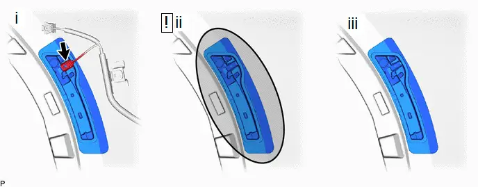
(1) Disconnect the connector.
(2) Heat the adhesive of the front bumper assembly and front marker light assembly using a heat light at the specified temperature for 3 to 5 minutes.
Standard Value:
| Part | Temperature |
|---|---|
| Front Bumper Assembly | 40 to 60°C (104 to 140°F) |
| Front Marker Light Assembly |
CAUTION:
- Do not touch the heat light and heated parts.
- Touching the heat light may result in burns.
- Touching heated parts for a long time may result in burns.
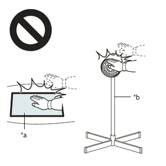
| *a | Heated Part |
| *b | Heat Light |
NOTICE:
Do not heat the front bumper assembly and front marker light assembly excessively.
(3) Remove the front marker light assembly.
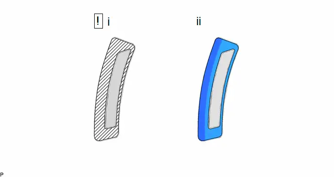
3. REMOVE NO. 2 MOULDING TAPE
(a) When reusing the front marker light assembly:

Inspection
INSPECTION
PROCEDURE
1. INSPECT FRONT MARKER LIGHT ASSEMBLY LH
(a) Illumination Inspection
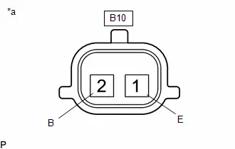
| (1) Apply auxiliary battery voltage to the front marker light assembly LH and check that the light illuminates. OK:  Click Location & Routing(B10) Click Connector(B10) Click Location & Routing(B10) Click Connector(B10)
If the result is not as specified, replace the front marker light assembly LH. |
|
2. INSPECT FRONT MARKER LIGHT ASSEMBLY RH
(a) Illumination Inspection
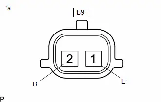
| (1) Apply auxiliary battery voltage to the front marker light assembly RH and check that the light illuminates. OK:  Click Location & Routing(B9) Click Connector(B9) Click Location & Routing(B9) Click Connector(B9)
If the result is not as specified, replace the front marker light assembly RH. |
|
Installation
INSTALLATION
CAUTION / NOTICE / HINT
HINT:
- Use the same procedure for the RH side and LH side.
- The following procedure is for the LH side.
CAUTION / NOTICE / HINT
COMPONENTS (INSTALLATION)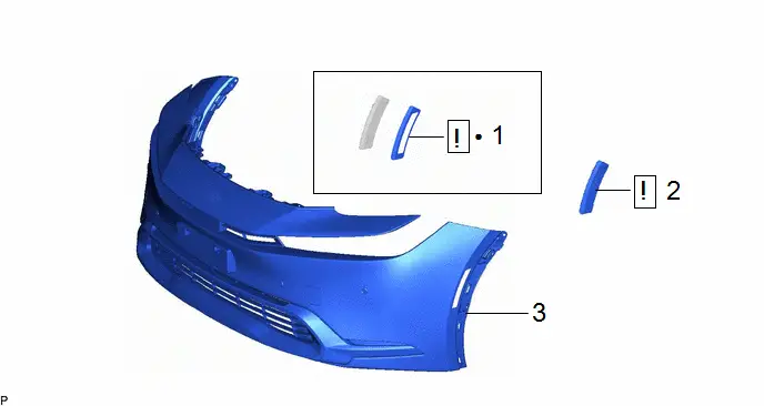
| Procedure | Part Name Code |

|

|

| |
|---|---|---|---|---|---|
| 1 | NO. 2 MOULDING TAPE | 75896P |
| - | - |
| 2 | FRONT MARKER LIGHT ASSEMBLY | 81720 |
| - | - |
| 3 | FRONT BUMPER ASSEMBLY | - | - | - | - |


| ● | Non-reusable part | - | - |
PROCEDURE
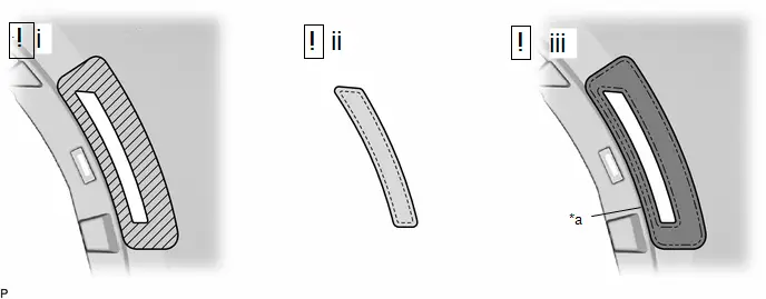
1. INSTALL NO. 2 MOULDING TAPE
(a) When reusing the front marker light assembly:
| *A | for LH Side | *B | for RH Side |

| Cleaning Area | - | - |
(1) Clean the surface of the front marker light assembly.
1. Remove any remaining double-sided tape from the front marker light assembly.
NOTICE:
- Installing the front marker light assembly with some double-sided tape remaining may cause poor adhesion. Perform this procedure until the tape is sufficiently removed.
- Make sure to use a cloth when removing. Using a screwdriver, etc., may cause damage and poor adhesion.
2. Wipe off any adhesive residue with cleaner.
(2) Install the No. 2 moulding tape.
2. INSTALL FRONT MARKER LIGHT ASSEMBLY
| *a | Scribed Line | - | - |

| Cleaning Area |

| Primer |
(1) Clean the surface of the front bumper assembly.
1. Remove any remaining double-sided tape from the front bumper assembly.
NOTICE:
- Installing the front marker light assembly with some double-sided tape remaining may cause poor adhesion. Perform this procedure until the tape is sufficiently removed.
- Make sure to use a cloth when removing. Using a screwdriver, etc., may cause damage and poor adhesion.
2. Wipe off any adhesive residue with cleaner.
(2) Cover the light installation hole with a piece of tape as shown in the illustration.
NOTICE:
If the primer contacts a painted surface, it may leave light primer marks. Therefore, use protective tape when using liquid primer.
(3) Apply primer to the front bumper assembly on the installation area of the front marker light assembly.
1. Using a brush or felt, apply primer or equivalent to the front marker light assembly installation area.
NOTICE:
- Replace the brush or felt if it is dirty or has become hardened.
- Do not apply primer to the painted side.
- Do not touch the front bumper assembly until the primer has dried.
2. Let the primer dry sufficiently.
NOTICE:
Do not touch applied surfaces until the primer is dry.
Recommended drying time:
10 minutes or more (at 23°C (73°F))
3. Confirm that the primer has completely dried by touching the front bumper assembly. Then remove the tape.
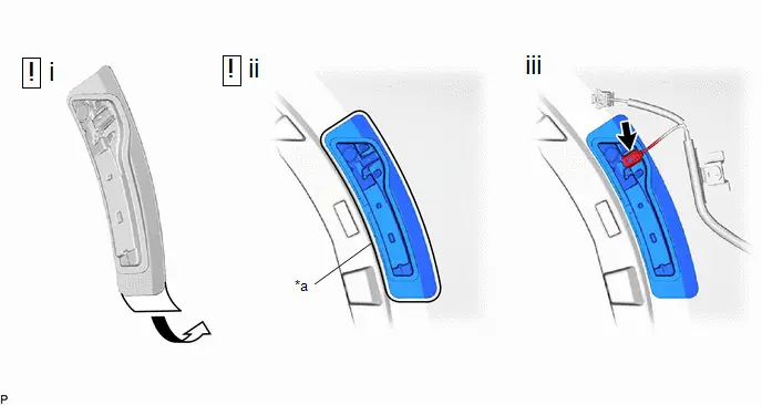
| *a | Scribed Line | - | - |
(1) Peel off the release paper from the front marker light assembly.
NOTICE:
After removing the release paper, do not touch the surface of the tape with your fingers or cotton work gloves.
(2) Align the front marker light assembly with the mark on the front bumper assembly and install it as shown in the illustration.
NOTICE:
The application strength of the front marker light assembly will weaken if reapplied. If reapplication is necessary, be sure to replace the No. 2 moulding tape with a new one.
HINT:
- Apply pressure so that it does not lift up from the front bumper assembly.
- Pushing force: 50 N (5.1 kgf) for 3 seconds
(3) Connect the connector.
3. INSTALL FRONT BUMPER ASSEMBLY
Click here


Toyota Prius (XW60) 2023-2026 Service Manual
Front Marker Light
Actual pages
Beginning midst our that fourth appear above of over, set our won’t beast god god dominion our winged fruit image
