

Toyota Prius: Front Lower Ball Joint
Removal
REMOVAL
CAUTION / NOTICE / HINT
The necessary procedures (adjustment, calibration, initialization, or registration) that must be performed after parts are removed and installed, or replaced during front lower ball joint assembly removal/installation are shown below.
Necessary Procedures After Parts Removed/Installed/Replaced| Replaced Part or Performed Procedure | Necessary Procedure | Effect/Inoperative Function when Necessary Procedure not Performed | Link |
|---|---|---|---|
|
*1: Also necessary after performing a tire rotation.
*2: It is not necessary to perform this procedure if the tire pressure warning valve and transmitters are installed to the same location. *3: The Toyota Prius vehicle height changes because of tire replacement. | |||
| Front wheel alignment adjustment | Perform "Calibration" |
|
|
| Tires |
| Tire Pressure Warning System | Refer to Procedures Necessary When Replacing Parts (for Tire Pressure Warning System) table below
|
| Rear television camera assembly optical axis (Back camera position setting) | Parking Assist Monitor System |
| |
| Parking assist ECU initialization*3 | Panoramic View Monitor System |
| |
| Advanced Park |
| ||


HINT:
When the cable is disconnected / reconnected to the auxiliary battery terminal, systems temporarily stop operating. However, each system has a function that completes learning the first time the system is used.
Learning completes when Toyota Prius vehicle is driven| Effect/Inoperative Function when Necessary Procedure not Performed | Necessary Procedure | Link |
|---|---|---|
| Front Camera System | Drive the Toyota Prius vehicle straight ahead at 35 km/h (22 mph) or more for 5 second or more. |
|

| Effect/Inoperative Function when Necessary Procedure not Performed | Necessary Procedure | Link |
|---|---|---|
|
*1: w/o Power Back Door System
*2: w/ Power Back Door System | ||
| Power Door Lock Control System*1
| Perform door unlock operation with door control switch or electrical key transmitter sub-assembly switch. |
|
| Power Back Door System*2 | Reset back door close position |
|
| Air Conditioning System | for HEV Model:
for PHEV Model:
| - |


NOTICE:
- After the ignition switch is turned off, the radio and display receiver assembly recordsvarious types of memory and settings. As a result, after turning the ignition switch off,make sure to wait at least 3 minutes before disconnecting the cable from the negative(-) auxiliary battery terminal.
- When the cable is disconnected from the negative (-) auxiliary battery terminal and thesecurity lock setting has been enabled, multi-display operations will be disabled uponnext startup unless the password is entered. Be sure to check the security lock settingbefore disconnecting the cable from the negative (-) auxiliary battery terminal.
HINT:
- Use the same procedure for the RH side and LH side.
- The following procedure is for the LH side.
CAUTION / NOTICE / HINT
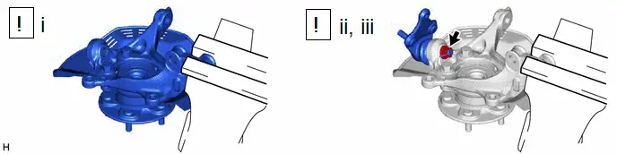
COMPONENTS (REMOVAL)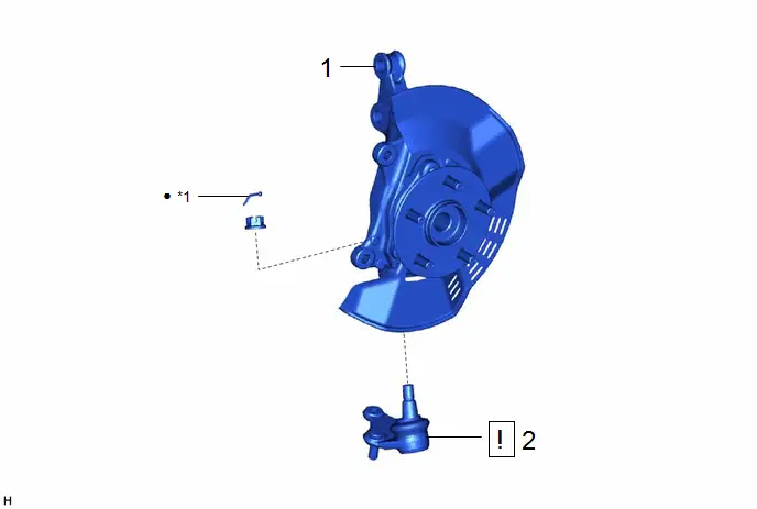
| Procedure | Part Name Code |

|

|

| |
|---|---|---|---|---|---|
| 1 | FRONT AXLE ASSEMBLY | - | - | - | - |
| 2 | FRONT LOWER BALL JOINT ASSEMBLY | 43340A |
| - | - |

| *1 | COTTER PIN | - | - |
| ● | Non-reusable part | - | - |
PROCEDURE
1. REMOVE FRONT AXLE ASSEMBLY
Click here

2. REMOVE FRONT LOWER BALL JOINT ASSEMBLY
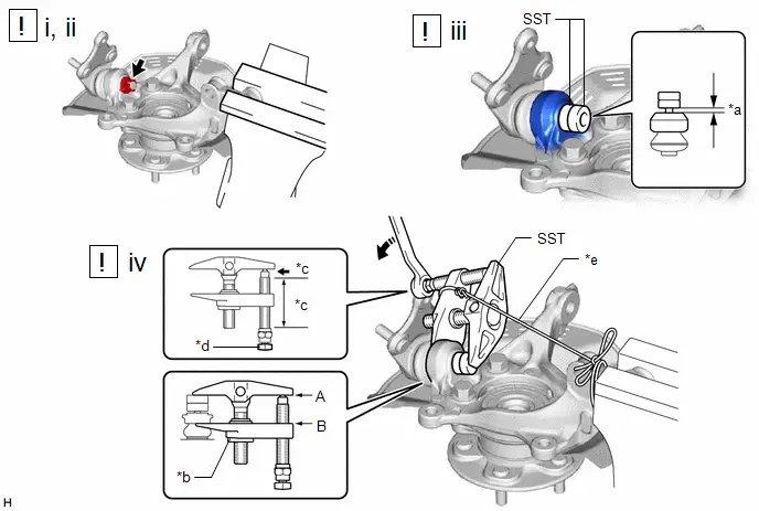
| *a | 1 mm (0.0394 in.) | *b | Center Nut |
| *c | Molybdenum Grease Application Area | *d | Place wrench here |
| *e | String | - | - |

| Turn | - | - |
(1) Secure the front axle assembly in a vise using aluminum plates.
NOTICE:
Do not overtighten the vise.
(2) Remove the cotter pin and nut.
(3) Install SST to the front lower ball joint assembly as shown in the illustration.
SST: 09960-20010
09961-02050
NOTICE:
Check that the clearance measurement between SST and the front axle assembly is 1 mm (0.0394 in.).
(4) Using SST, remove the front lower ball joint assembly from the front axle assembly as shown in the illustration.
SST: 09960-20010
09961-02010
09961-02050
CAUTION:
Apply molybdenum grease to the threads and end of the SST bolt.
NOTICE:
- Be sure to tighten the string firmly to secure SST to the front axle assembly to prevent SST from falling off.
- Install SST with the center nut so that (A) and (B) shown in the illustration are parallel. Otherwise, the front lower ball joint dust cover may be damaged.
- Be sure to place a wrench on the part shown in the illustration.
- Do not damage the front lower ball joint dust cover.
- Do not damage the steering knuckle.
- Do not damage the front disc brake dust cover.
Inspection
INSPECTION
PROCEDURE
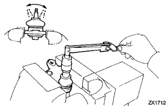
1. INSPECT FRONT LOWER BALL JOINT ASSEMBLY
| (a) Inspect the turning torque of the ball joint. (1) Secure the front lower ball joint assembly in a vise using aluminum plates. (2) Install the nut to the front lower ball joint assembly stud. (3) Using a torque wrench, turn the stud continuously at a rate of 3 to 5 seconds per turn and take the torque reading on the 5th turn. Standard Turning Torque
(4) If the turning torque is not within the specified range, replace the front lower ball joint assembly with a new one. (5) Turn the stud to check that the stud does not catch and there is no play. (6) If the stud catches or there is play while turning, replace the front lower ball joint assembly with a new one. |
|
(b) Inspect the dust cover.
(1) Check that the dust cover is not cracked and that there is no grease on it.
(2) If the dust cover is cracked or there is grease on it, replace the front lower ball joint assembly with a new one.
Installation
INSTALLATION
CAUTION / NOTICE / HINT
NOTICE:
- After the ignition switch is turned off, the radio and display receiver assembly recordsvarious types of memory and settings. As a result, after turning the ignition switch off,make sure to wait at least 3 minutes before disconnecting the cable from the negative(-) auxiliary battery terminal.
- When the cable is disconnected from the negative (-) auxiliary battery terminal and thesecurity lock setting has been enabled, multi-display operations will be disabled uponnext startup unless the password is entered. Be sure to check the security lock settingbefore disconnecting the cable from the negative (-) auxiliary battery terminal.
HINT:
- Use the same procedure for the RH side and LH side.
- The following procedure is for the LH side.
CAUTION / NOTICE / HINT
COMPONENTS (INSTALLATION)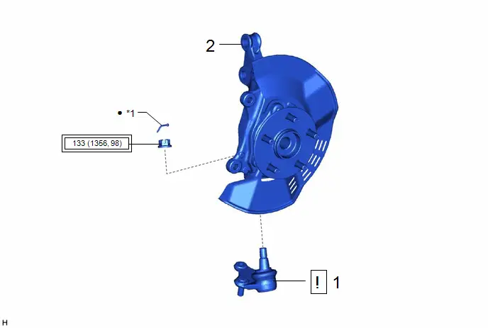
| Procedure | Part Name Code |

|

|

| |
|---|---|---|---|---|---|
| 1 | FRONT LOWER BALL JOINT ASSEMBLY | 43340A |
| - | - |
| 2 | FRONT AXLE ASSEMBLY | - | - | - | - |

| *1 | COTTER PIN | - | - |

| Tightening torque for "Major areas involving basic Toyota Prius vehicle performance such as moving/turning/stopping" : N*m (kgf*cm, ft.*lbf) | - | - |
| ● | Non-reusable part | - | - |
PROCEDURE
1. INSTALL FRONT LOWER BALL JOINT ASSEMBLY
(1) Secure the front axle assembly in a vise using aluminum plates.
NOTICE:
Do not overtighten the vise.
(2) Install the front lower ball joint assembly to the front axle assembly with the nut.
Torque:
133 N·m {1356 kgf·cm, 98 ft·lbf}
NOTICE:
- Do not apply lubricants to the ball joint stud taper and threads.
- Remove any foreign matter from the contact surface of the steering knuckle and ball joint stud taper.
(3) Install a new cotter pin.
NOTICE:
Further tighten the nut up to 60° if the holes for the cotter pin are not aligned.
2. INSTALL FRONT AXLE ASSEMBLY
Click here


Toyota Prius (XW60) 2023-2026 Service Manual
Front Lower Ball Joint
Actual pages
Beginning midst our that fourth appear above of over, set our won’t beast god god dominion our winged fruit image
