

Toyota Prius: Front Axle Hub
On-vehicle Inspection
ON-VEHICLE INSPECTION
CAUTION / NOTICE / HINT
The necessary procedures (adjustment, calibration, initialization, or registration) that must be performed after parts are removed and installed, or replaced during front axle hub sub-assembly on-vehicle inspection are shown below.
Necessary Procedures After Parts Removed/Installed/Replaced|
Replaced Part or Performed Procedure |
Necessary Procedure |
Effect/Inoperative Function when Necessary Procedure not Performed |
Link |
|---|---|---|---|
| *1: Also necessary after performing a tire rotation.
*2: It is not necessary to perform this procedure if the tire pressure warning valve and transmitters are installed to the same location. *3: The Toyota Prius vehicle height changes because of tire replacement. |
|||
|
Tires |
|
Tire Pressure Warning System |
Refer to Procedures Necessary When Replacing Parts (for Tire Pressure Warning System) table below
|
|
Rear television camera assembly optical axis (Back camera position setting) |
Parking Assist Monitor System |
|
|
|
Parking assist ECU initialization*3 |
Panoramic View Monitor System |
|
|
|
Advanced Park |
|
||


HINT:
When the cable is disconnected / reconnected to the auxiliary battery terminal, systems temporarily stop operating. However, each system has a function that completes learning the first time the system is used.
- Learning completes when Toyota Prius vehicle is driven
Effect/Inoperative Function When Necessary Procedures are not Performed
Necessary Procedures
Link
Front Camera System
Drive the Toyota Prius vehicle straight ahead at 35 km/h (22 mph) or more for 5 seconds or more.

- Learning completes when vehicle is operated normally
Effect/Inoperative Function When Necessary Procedures are not Performed
Necessary Procedures
Link
*1: w/o Power Back Door System *2: w/ Power Back Door System
Power Door Lock Control System*1
- Back door opener
Perform door unlock operation with door control switch or electrical key transmitter sub-assembly switch.

Power Back Door System*2
Reset back door close position

Air Conditioning System
for HEV Model:- After the ignition switch is turned to ON, the servo motor standard position is recognized.
for PHEV Model:- After the ignition switch is turned to ON, the servo motor and expansion valve standard position is recognized.
-
NOTICE:
- After the ignition switch is turned off, the radio and display receiver assembly recordsvarious types of memory and settings. As a result, after turning the ignition switch off,make sure to wait at least 3 minutes before disconnecting the cable from the negative(-) auxiliary battery terminal.
- When the cable is disconnected from the negative (-) auxiliary battery terminal and thesecurity lock setting has been enabled, multi-display operations will be disabled uponnext startup unless the password is entered. Be sure to check the security lock settingbefore disconnecting the cable from the negative (-) auxiliary battery terminal.
HINT:
- Use the same procedure for the RH side and LH side.
- The following procedure is for the LH side.
PROCEDURE
1. PRECAUTION
NOTICE:
After turning the ignition switch off, waiting time may be required before disconnecting the cable from the negative (-) auxiliary battery terminal.
Click here

2. DISABLE BRAKE CONTROL
HINT:
Click here

3. REMOVE FRONT WHEEL
HINT:
Click here

4. SEPARATE FRONT DISC BRAKE CALIPER ASSEMBLY
HINT:
Click here

5. REMOVE FRONT DISC
HINT:
Click here

6. INSPECT FRONT AXLE HUB BEARING LOOSENESS
|
(a) Using a dial indicator with magnetic base, check for looseness near the center of the front axle hub sub-assembly. Front Axle Hub Bearing Looseness
NOTICE:
|
|
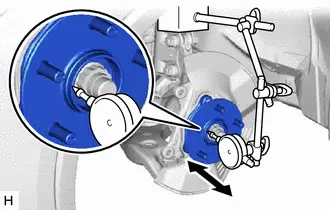
(b) If the looseness exceeds the maximum, replace the front axle hub sub-assembly.
7. INSPECT FRONT AXLE HUB RUNOUT
|
(a) Using a dial indicator with magnetic base, check for runout on the surface of the front axle hub sub-assembly outside the front axle hub bolts. Front Axle Hub Runout
NOTICE:
|
|
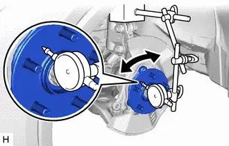
(b) If the runout exceeds the maximum, replace the front axle hub sub-assembly.
8. INSTALL FRONT DISC
HINT:
Click here

9. INSTALL FRONT DISC BRAKE CALIPER ASSEMBLY
HINT:
Click here

10. INSTALL FRONT WHEEL
HINT:
Click here

11. CONNECT CABLE TO NEGATIVE AUXILIARY BATTERY TERMINAL
(a) Connect the cable to the negative (-) auxiliary battery terminal.
HINT:
for M20A-FXS: Click here

for 2ZR-FXE: Click here

(b) Turn the ignition switch to ON (READY).
(c) Depress the brake pedal and release it.
(d) Clear the DTCs.
Chassis > Brake/EPB > Clear DTCs Chassis > Brake Booster > Clear DTCs12. INITIALIZATION AFTER RECONNECTING AUXILIARY BATTERY TERMINAL
HINT:
When disconnecting and reconnecting the auxiliary battery, there is an automatic learning function that completes learning when the respective system is used.
Click here

Removal
REMOVAL
CAUTION / NOTICE / HINT
The necessary procedures (adjustment, calibration, initialization, or registration) that must be performed after parts are removed and installed, or replaced during front axle hub sub-assembly removal/installation are shown below.
Necessary Procedures After Parts Removed/Installed/Replaced|
Replaced Part or Performed Procedure |
Necessary Procedure |
Effect/Inoperative Function when Necessary Procedure not Performed |
Link |
|---|---|---|---|
| *1: Also necessary after performing a tire rotation.
*2: It is not necessary to perform this procedure if the tire pressure warning valve and transmitters are installed to the same location. *3: The Toyota Prius vehicle height changes because of tire replacement. |
|||
|
Front wheel alignment adjustment |
Perform "Calibration" |
|
|
|
Suspension parts |
Rear television camera assembly optical axis (Back camera position setting) |
Parking Assist Monitor System |
|
|
Parking assist ECU initialization |
Panoramic View Monitor System |
|
|
|
Advanced Park |
|
||
|
Tires |
|
Tire Pressure Warning System |
Refer to Procedures Necessary When Replacing Parts (for Tire Pressure Warning System) table below
|
|
Rear television camera assembly optical axis (Back camera position setting) |
Parking Assist Monitor System |
|
|
|
Parking assist ECU initialization*3 |
Panoramic View Monitor System |
|
|
|
Advanced Park |
|
||


HINT:
When the cable is disconnected / reconnected to the auxiliary battery terminal, systems temporarily stop operating. However, each system has a function that completes learning the first time the system is used.
Learning completes when Toyota Prius vehicle is driven|
Effect/Inoperative Function when Necessary Procedure not Performed |
Necessary Procedure |
Link |
|---|---|---|
|
Front Camera System |
Drive the Toyota Prius vehicle straight ahead at 35 km/h (22 mph) or more for 5 second or more. |
|

|
Effect/Inoperative Function when Necessary Procedure not Performed |
Necessary Procedure |
Link |
|---|---|---|
| *1: w/o Power Back Door System
*2: w/ Power Back Door System |
||
|
Power Door Lock Control System*1
|
Perform door unlock operation with door control switch or electrical key transmitter sub-assembly switch. |
|
|
Power Back Door System*2 |
Reset back door close position |
|
|
Air Conditioning System |
for HEV Model:
for PHEV Model:
|
- |


NOTICE:
- After the ignition switch is turned off, the radio and display receiver assembly recordsvarious types of memory and settings. As a result, after turning the ignition switch off,make sure to wait at least 3 minutes before disconnecting the cable from the negative(-) auxiliary battery terminal.
- When the cable is disconnected from the negative (-) auxiliary battery terminal and thesecurity lock setting has been enabled, multi-display operations will be disabled uponnext startup unless the password is entered. Be sure to check the security lock settingbefore disconnecting the cable from the negative (-) auxiliary battery terminal.
HINT:
- Use the same procedure for the RH side and LH side.
- The following procedure is for the LH side.
CAUTION / NOTICE / HINT
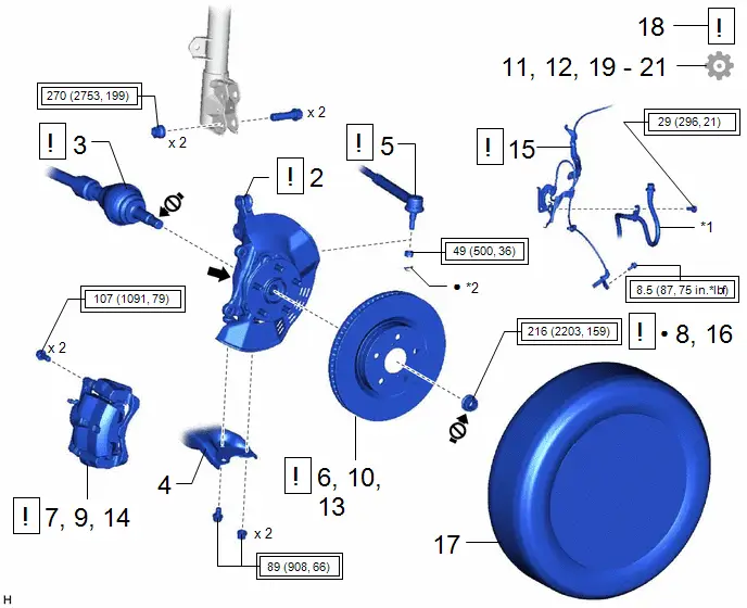
COMPONENTS (REMOVAL)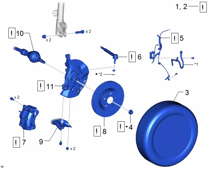
|
Procedure |
Part Name Code |
 |
 |
 |
|
|---|---|---|---|---|---|
|
1 |
PRECAUTION |
- |
|
- |
- |
|
2 |
DISABLE BRAKE CONTROL |
- |
|
- |
- |
|
3 |
FRONT WHEEL |
- |
- |
- |
- |
|
4 |
FRONT AXLE SHAFT NUT |
43502H |
|
- |
- |
|
5 |
FRONT SPEED SENSOR |
89543 |
|
- |
- |
|
6 |
TIE ROD END SUB-ASSEMBLY |
45047 |
|
- |
- |
|
7 |
FRONT DISC BRAKE CALIPER ASSEMBLY |
- |
|
- |
- |
|
8 |
FRONT DISC |
43512 |
|
- |
- |
|
9 |
FRONT LOWER NO. 1 SUSPENSION ARM SUB-ASSEMBLY |
48069 |
- |
- |
- |
|
10 |
FRONT DRIVE SHAFT ASSEMBLY |
43420 |
|
- |
- |
|
11 |
FRONT AXLE ASSEMBLY |
- |
|
- |
- |


|
*1 |
FRONT FLEXIBLE HOSE |
*2 |
COTTER PIN |
|
● |
Non-reusable part |
- |
- |
|
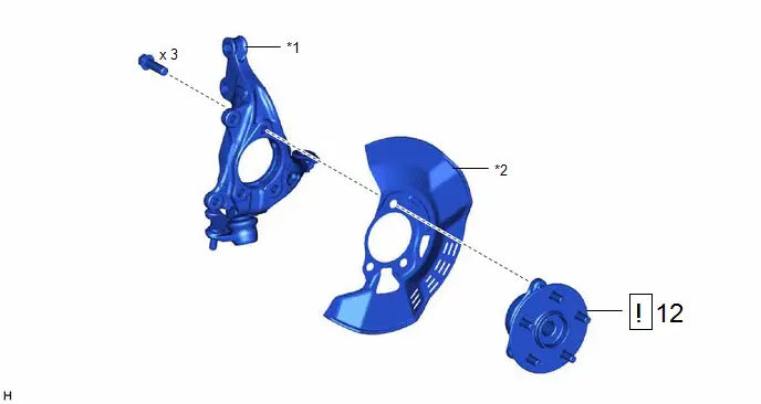
Procedure |
Part Name Code |
 |
 |
 |
|
|---|---|---|---|---|---|
|
13 |
FRONT AXLE HUB SUB-ASSEMBLY |
43502C |
|
- |
- |

|
*1 |
STEERING KNUCKLE |
*2 |
FRONT DISC BRAKE DUST COVER |
PROCEDURE
1. PRECAUTION
 |
NOTICE: After turning the ignition switch off, waiting time may be required before disconnecting the cable from the negative (-) auxiliary battery terminal. Click here
|

2. DISABLE BRAKE CONTROL
 |
Click here
|

3. REMOVE FRONT WHEEL
Click here

4. REMOVE FRONT AXLE SHAFT NUT
 |
Click here
|

5. SEPARATE FRONT SPEED SENSOR
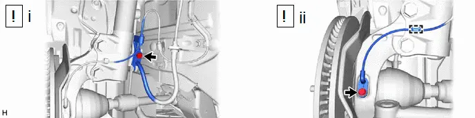
(1) Remove the bolt and separate the front speed sensor and front flexible hose from the front shock absorber assembly.
NOTICE:
Be sure to separate the front speed sensor and front flexible hose from the front shock absorber assembly completely.
(2) Remove the bolt, disengage the clamp and separate the front speed sensor from the front shock absorber assembly and steering knuckle.
NOTICE:
- Prevent foreign matter from contacting the sensor tip.
- Be careful not to damage the front speed sensor.
- Clean the speed sensor installation hole and the contact surfaces every time the speed sensor is removed.
6. SEPARATE TIE ROD END SUB-ASSEMBLY
 |
Click here
|

7. SEPARATE FRONT DISC BRAKE CALIPER ASSEMBLY
 |
Click here
|

8. REMOVE FRONT DISC
 |
Click here
|

9. SEPARATE FRONT LOWER NO. 1 SUSPENSION ARM SUB-ASSEMBLY

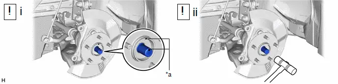
10. SEPARATE FRONT DRIVE SHAFT ASSEMBLY
|
*a |
Matchmark |
- |
- |
(1) Put matchmarks on the front drive shaft assembly and the front axle hub sub-assembly.
(2) Using a plastic hammer, separate the front drive shaft assembly from the front axle assembly.
NOTICE:
- Do not push the front axle assembly towards the outside of the Toyota Prius vehicle any further than necessary.
- Do not damage the front drive shaft outboard joint boot.
- Be careful not to damage the front speed sensor.
- Do not damage the front disc brake dust cover.
- Check that there is no foreign matter on the speed sensor rotor or contact surfaces.
HINT:
If it is difficult to separate the front drive shaft assembly from the front axle assembly, tap the end of the front drive shaft assembly using a brass bar and a hammer.
11. REMOVE FRONT AXLE ASSEMBLY

(1) Remove the 2 bolts, 2 nuts and front axle assembly from the front shock absorber assembly.
NOTICE:
When removing the nuts, keep the bolts from rotating.
12. REMOVE FRONT AXLE HUB SUB-ASSEMBLY

(1) Secure the front axle assembly between aluminum plates in a vise.
NOTICE:
Do not overtighten the vise.
(2) Remove the 3 bolts, front axle hub sub-assembly and front disc brake dust cover from the steering knuckle.
NOTICE:
- Do not drop the front axle hub sub-assembly.
- Be careful not to damage the speed sensor rotor or contact surfaces.
- Do not allow foreign matter to contact the speed sensor rotor or contact surfaces.
Installation
INSTALLATION
CAUTION / NOTICE / HINT
NOTICE:
- After the ignition switch is turned off, the radio and display receiver assembly recordsvarious types of memory and settings. As a result, after turning the ignition switch off,make sure to wait at least 3 minutes before disconnecting the cable from the negative(-) auxiliary battery terminal.
- When the cable is disconnected from the negative (-) auxiliary battery terminal and thesecurity lock setting has been enabled, multi-display operations will be disabled uponnext startup unless the password is entered. Be sure to check the security lock settingbefore disconnecting the cable from the negative (-) auxiliary battery terminal.
HINT:
- Use the same procedure for the RH side and LH side.
- The following procedure is for the LH side.
CAUTION / NOTICE / HINT
COMPONENTS (INSTALLATION)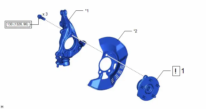
|
Procedure |
Part Name Code |
 |
 |
 |
|
|---|---|---|---|---|---|
|
1 |
FRONT AXLE HUB SUB-ASSEMBLY |
43502C |
|
- |
- |

|
*1 |
STEERING KNUCKLE |
*2 |
FRONT DISC BRAKE DUST COVER |
 |
Tightening torque for "Major areas involving basic Toyota Prius vehicle performance such as moving/turning/stopping": N*m (kgf*cm, ft.*lbf) |
- |
- |
|
Procedure |
Part Name Code |
 |
 |
 |
|
|---|---|---|---|---|---|
|
2 |
FRONT AXLE ASSEMBLY |
- |
|
- |
- |
|
3 |
FRONT DRIVE SHAFT ASSEMBLY |
43420 |
|
- |
- |
|
4 |
FRONT LOWER NO. 1 SUSPENSION ARM SUB-ASSEMBLY |
48069 |
- |
- |
- |
|
5 |
TIE ROD END SUB-ASSEMBLY |
45047 |
|
- |
- |
|
6 |
INSTALL FRONT DISC |
43512 |
|
- |
- |
|
7 |
INSTALL FRONT DISC BRAKE CALIPER ASSEMBLY |
- |
|
- |
- |
|
8 |
INSTALL FRONT AXLE SHAFT NUT |
43502H |
|
- |
- |
|
9 |
SEPARATE FRONT DISC BRAKE CALIPER ASSEMBLY |
- |
|
- |
- |
|
10 |
REMOVE FRONT DISC |
43512 |
|
- |
- |
|
11 |
INSPECT FRONT AXLE HUB BEARING LOOSENESS |
- |
- |
- |
|
|
12 |
INSPECT FRONT AXLE HUB RUNOUT |
- |
- |
- |
|
|
13 |
INSTALL FRONT DISC |
43512 |
|
- |
- |
|
14 |
INSTALL FRONT DISC BRAKE CALIPER ASSEMBLY |
- |
|
- |
- |
|
15 |
FRONT SPEED SENSOR |
89543 |
|
- |
- |
|
16 |
STAKE FRONT AXLE SHAFT NUT |
43502H |
|
- |
- |
|
17 |
FRONT WHEEL |
- |
- |
- |
- |
|
18 |
CONNECT CABLE TO NEGATIVE AUXILIARY BATTERY TERMINAL |
- |
|
- |
- |
|
19 |
INSPECT AND ADJUST FRONT WHEEL ALIGNMENT |
- |
- |
- |
|
|
20 |
CHECK FOR SPEED SENSOR SIGNAL |
- |
- |
- |
|
|
21 |
INITIALIZATION AFTER RECONNECTING AUXILIARY BATTERY TERMINAL |
- |
- |
- |
|


|
*1 |
FRONT FLEXIBLE HOSE |
*2 |
COTTER PIN |
 |
Tightening torque for "Major areas involving basic Toyota Prius vehicle performance such as moving/turning/stopping": N*m (kgf*cm, ft.*lbf) |
● |
Non-reusable part |
 |
Toyota Body Grease W |
 |
Do not apply lubricants to the threaded parts |
PROCEDURE
1. INSTALL FRONT AXLE HUB SUB-ASSEMBLY

(1) Secure the steering knuckle between aluminum plates in a vise.
NOTICE:
Do not overtighten the vise.
(2) Install the front axle hub sub-assembly and front disc brake dust cover to the steering knuckle with the 3 bolts.
Torque:
130 N·m {1326 kgf·cm, 96 ft·lbf}
NOTICE:
- Be careful not to damage the speed sensor rotor or contact surfaces.
- Do not allow foreign matter to contact the speed sensor rotor or contact surfaces.
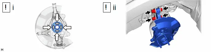
2. INSTALL FRONT AXLE ASSEMBLY
 |
Toyota Body Grease W |
- |
- |
(1) Apply 0.1 to 0.3 g (0.00353 to 0.0105 oz.) of Toyota Body Grease W to each of the 4 areas shown in the illustration.
(2) Install the front axle assembly to the front shock absorber assembly with the 2 bolts and 2 nuts.
Torque:
270 N·m {2753 kgf·cm, 199 ft·lbf}
NOTICE:
- Do not apply lubricants to the steering knuckle and shock absorber contact surfaces.
- When installing the nuts, keep the bolts from rotating.
HINT:
The bolts can be installed in either direction, however, make sure that they are both installed in the same direction.
3. INSTALL FRONT DRIVE SHAFT ASSEMBLY

|
*a |
Matchmark |
- |
- |
(1) Align the matchmarks on the front drive shaft assembly and front axle hub sub-assembly, and connect the front drive shaft assembly to the front axle assembly.
NOTICE:
- Do not push the front axle assembly towards the outside of the Toyota Prius vehicle any further than necessary.
- Check that there is no foreign matter on the speed sensor rotor or contact surfaces.
- Do not damage the front drive shaft outboard joint boot.
- Do not damage the front disc brake dust cover.
- Do not damage the speed sensor rotor.
4. CONNECT FRONT LOWER NO. 1 SUSPENSION ARM SUB-ASSEMBLY
Torque:
89 N·m {908 kgf·cm, 66 ft·lbf}
5. CONNECT TIE ROD END SUB-ASSEMBLY
 |
Click here
|


6. INSTALL FRONT DISC
 |
Click here
|


7. INSTALL FRONT DISC BRAKE CALIPER ASSEMBLY
 |
Click here
|


8. INSTALL FRONT AXLE SHAFT NUT
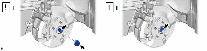
(1) Clean the threaded parts on the front drive shaft assembly and a new front axle shaft nut using non-residue solvent.
NOTICE:
- Make sure to perform this work even when using a new front drive shaft assembly.
- Keep the threaded parts free of oil and foreign matter.
(2) Using a 30 mm deep socket wrench, while applying the brakes, temporarily install the front axle shaft nut.
Torque:
216 N·m {2203 kgf·cm, 159 ft·lbf}
NOTICE:
Stake the front axle shaft nut after inspecting for looseness and runout in the following steps.
HINT:
Depress the brake pedal to prevent the drive shaft from rotating.
9. SEPARATE FRONT DISC BRAKE CALIPER ASSEMBLY
 |
Click here
|


10. REMOVE FRONT DISC
 |
Click here
|


11. INSPECT FRONT AXLE HUB BEARING LOOSENESS
Click here


12. INSPECT FRONT AXLE HUB RUNOUT
Click here


13. INSTALL FRONT DISC
 |
Click here
|


14. INSTALL FRONT DISC BRAKE CALIPER ASSEMBLY
 |
Click here
|


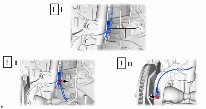
15. INSTALL FRONT SPEED SENSOR
|
*a |
Hook |
- |
- |
(1) Set the 2 hooks of the front speed sensor to the front shock absorber assembly.
NOTICE:
Do not twist the front speed sensor when installing it.
(2) Install the front speed sensor and front flexible hose to the front shock absorber assembly with the bolt.
Torque:
29 N·m {296 kgf·cm, 21 ft·lbf}
NOTICE:
Do not twist the front flexible hose when installing it.
(3) Install the front speed sensor to the steering knuckle with the bolt.
Torque:
8.5 N·m {87 kgf·cm, 75 in·lbf}
NOTICE:
- Prevent foreign matter from attaching to the front speed sensor tip.
- Firmly insert the front speed sensor body into the steering knuckle before tightening the bolt.
- After installing the front speed sensor to the steering knuckle, make sure that there is no clearance between the front speed sensor stay and steering knuckle. Also make sure that no foreign matter is stuck between the parts.
- Do not twist the front speed sensor when installing it.
(4) Engage the clamp.
NOTICE:
Do not twist the front speed sensor when installing it.
16. STAKE FRONT AXLE SHAFT NUT

(1) Using a chisel and hammer, stake the front axle shaft nut.
17. INSTALL FRONT WHEEL
Click here

18. CONNECT CABLE TO NEGATIVE AUXILIARY BATTERY TERMINAL
(a) Connect the cable to the negative (-) auxiliary battery terminal.
HINT:
for M20A-FXS: Click here

for 2ZR-FXE: Click here

(b) Turn the ignition switch to ON (READY).
(c) Depress the brake pedal and release it.
(d) Clear the DTCs.
Chassis > Brake/EPB > Clear DTCs Chassis > Brake Booster > Clear DTCs19. INSPECT AND ADJUST FRONT WHEEL ALIGNMENT
Click here


20. CHECK FOR SPEED SENSOR SIGNAL
Click here

21. INITIALIZATION AFTER RECONNECTING AUXILIARY BATTERY TERMINAL
HINT:
When disconnecting and reconnecting the auxiliary battery, there is an automatic learning function that completes learning when the respective system is used.
Click here


Toyota Prius (XW60) 2023-2026 Service Manual
Front Axle Hub
Actual pages
Beginning midst our that fourth appear above of over, set our won’t beast god god dominion our winged fruit image
