

Toyota Prius: Exhaust Pipe
Removal
REMOVAL
CAUTION / NOTICE / HINT
The necessary procedures (adjustment, calibration, initialization or registration) that must be performed after parts are removed and installed, or replaced during front exhaust pipe assembly and tail exhaust pipe assembly removal/installation are shown below.
Necessary Procedures After Parts Removed/Installed/Replaced| Replaced Part or Performed Procedure | Necessary Procedure | Effect/Inoperative Function when Necessary Procedure not Performed | Link |
|---|---|---|---|
| Gas leak from exhaust system is repaired | Inspection after repair |
|
|

CAUTION:
To prevent burns, do not touch the engine, exhaust pipe or other high temperature components while the engine is hot.
 COMPONENTS (REMOVAL)
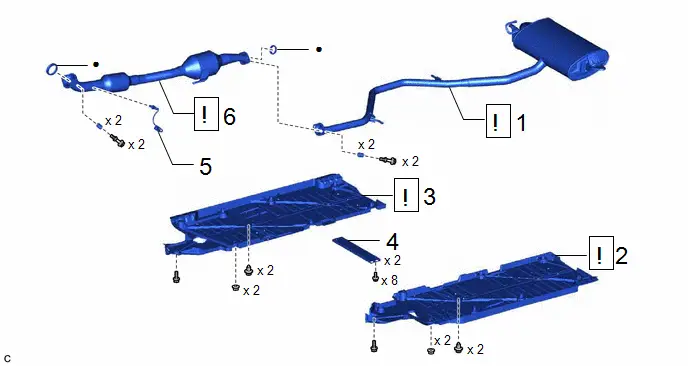
| Procedure | Part Name Code |

|

|

| |
|---|---|---|---|---|---|
| 1 | TAIL EXHAUST PIPE ASSEMBLY | 17430 |
| - | - |
| 2 | REMOVE FRONT FLOOR COVER LH | 58166A |
| - | - |
| 3 | REMOVE FRONT FLOOR COVER RH | 58165C |
| - | - |
| 4 | FRONT FLOOR CENTER BRACE | 57533B | - | - | - |
| 5 | HEATED OXYGEN SENSOR | 89465 | - | - | - |
| 6 | FRONT EXHAUST PIPE ASSEMBLY | 17410 |
| - | - |


| ● | Non-reusable part | - | - |
CAUTION / NOTICE / HINT
PROCEDURE
1. REMOVE TAIL EXHAUST PIPE ASSEMBLY

| CAUTION: To prevent burns, do not touch the engine, exhaust pipe or other high temperature components while the engine is hot. |
2. REMOVE FRONT FLOOR COVER LH

| Click here
|

3. REMOVE FRONT FLOOR COVER RH

| Click here
|

4. REMOVE FRONT FLOOR CENTER BRACE
Click here

5. REMOVE HEATED OXYGEN SENSOR
Click here

6. REMOVE FRONT EXHAUST PIPE ASSEMBLY

| CAUTION: To prevent burns, do not touch the engine, exhaust pipe or other high temperature components while the engine is hot. |
Installation
INSTALLATION
CAUTION / NOTICE / HINT
COMPONENTS (INSTALLATION)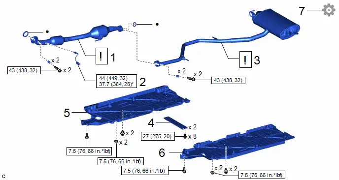
| Procedure | Part Name Code |

|

|

| |
|---|---|---|---|---|---|
| 1 | FRONT EXHAUST PIPE ASSEMBLY | 17410 |
| - | - |
| 2 | HEATED OXYGEN SENSOR | 89465 | - | - | - |
| 3 | TAIL EXHAUST PIPE ASSEMBLY | 17430 |
| - | - |
| 4 | FRONT FLOOR CENTER BRACE | 57533B | - | - | - |
| 5 | REMOVE FRONT FLOOR COVER RH | 58165C | - | - | - |
| 6 | REMOVE FRONT FLOOR COVER LH | 58166A | - | - | - |
| 7 | INSPECT FOR EXHAUST GAS LEAK | - | - | - |
|


| N*m (kgf*cm, ft.*lbf): Specified torque | ● | Non-reusable part |
| * | For use with SST | - | - |
PROCEDURE
1. INSTALL FRONT EXHAUST PIPE ASSEMBLY
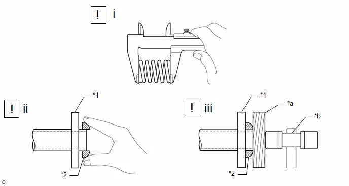
| *1 | Exhaust Manifold | *2 | Gasket |
| *a | Wooden Block | *b | Plastic Hammer |
(1) Using a vernier caliper, measure the free length of the compression springs.
| Standard Length | 43 mm (1.69 in.) |
| Minimum Free Length | 41.5 mm (1.63 in.) |
If the free length is less than the minimum, replace the compression spring.
(2) Temporarily install a new gasket to the exhaust manifold.
(3) Using a plastic hammer and wooden block, tap in the gasket until its surface is flush with the exhaust manifold.
NOTICE:
- Be careful with the installation direction of the gasket.
- Do not reuse the gasket.
- Do not damage the gasket.
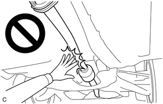
- Do not push in the gasket by using the exhaust pipes when connecting them.
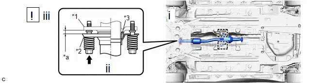
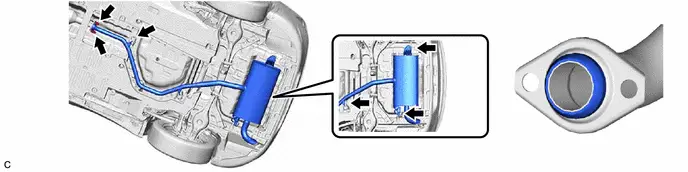
| *1 | Exhaust Manifold | *2 | Front Exhaust Pipe Assembly |
| *3 | Gasket | - | - |
| *a | Space between Flanges: 8.5 mm (0.335 in.) | - | - |
(1) Connect the front exhaust pipe assembly to the 2 exhaust pipe supports.
(2) Install the front exhaust pipe assembly to the exhaust manifold with the 2 compression springs and 2 bolts.
Torque:
43 N·m {438 kgf·cm, 32 ft·lbf}
(3) After installation, check that the space between the flanges of the exhaust manifold and front exhaust pipe assembly is consistent front-to-rear and left-to-right.
2. INSTALL HEATED OXYGEN SENSOR
Click here

3. INSTALL TAIL EXHAUST PIPE ASSEMBLY
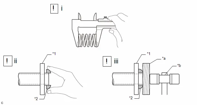
| *1 | Front Exhaust Pipe Assembly | *2 | Gasket |
| *a | Wooden Block | *b | Plastic Hammer |
(1) Using a vernier caliper, measure the free length of the compression springs.
| Standard Length | 40 mm (1.57 in.) |
| Minimum Free Length | 38.5 mm (1.52 in.) |
If the free length is less than the minimum, replace the compression spring.
(2) Temporarily install a new gasket to the front exhaust pipe assembly.
(3) Using a plastic hammer and wooden block, tap in the gasket until its surface is flush with the front exhaust pipe assembly.
NOTICE:
- Be careful with the installation direction of the gasket.
- Do not reuse the gasket.
- Do not damage the gasket.
- Do not push in the gasket by using the exhaust pipes when connecting them.
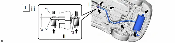
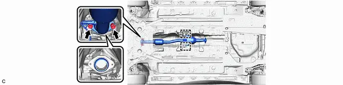
| *1 | Front Exhaust Pipe Assembly | *2 | Tail Exhaust Pipe Assembly |
| *3 | Gasket | - | - |
| *a | Space between Flanges: 6.5 mm (0.256 in.) | - | - |
(1) Connect the tail exhaust pipe assembly to the 4 exhaust pipe supports.
(2) Install the tail exhaust pipe assembly to the front exhaust pipe assembly with the 2 compression springs and 2 bolts.
Torque:
43 N·m {438 kgf·cm, 32 ft·lbf}
(3) After installation, check that the space between the flanges of the tail exhaust pipe assembly and front exhaust pipe assembly is consistent front-to-rear and left-to-right.
4. INSTALL FRONT FLOOR CENTER BRACE
Torque:
27 N·m {275 kgf·cm, 20 ft·lbf}
5. INSTALL FRONT FLOOR COVER RH
Torque:
7.5 N·m {76 kgf·cm, 66 in·lbf}
6. INSTALL FRONT FLOOR COVER LH
Torque:
7.5 N·m {76 kgf·cm, 66 in·lbf}
7. INSPECT FOR EXHAUST GAS LEAK
If gas is leaking, tighten the areas necessary to stop the leak. Replace damaged parts as necessary.
(a) Perform "Inspection After Repair" after repairing an exhaust gas leak.
Click here


Toyota Prius (XW60) 2023-2026 Service Manual
Exhaust Pipe
Actual pages
Beginning midst our that fourth appear above of over, set our won’t beast god god dominion our winged fruit image
