

Toyota Prius: Engine Unit
Precaution
PRECAUTION
HINT:
- Any digits beyond the 0.01 mm (1/1000 in.) place for standard, minimum and maximum values should be used as a reference only.
- When both standard and maximum or minimum values are listed for an inspection, use the standard value as a reference only and base any judgments on the maximum and minimum values.
Removal
REMOVAL
CAUTION / NOTICE / HINT
The necessary procedures (adjustment, calibration, initialization or registration) that must be performed after parts are removed and installed, or replaced during engine unit removal/installation are shown below.
Necessary Procedures After Parts Removed/Installed/Replaced| Replaced Part or Performed Procedure | Necessary Procedure | Effect/Inoperative Function when Necessary Procedure not Performed | Link |
|---|---|---|---|
|
*: Even when not replacing the part, it is necessary to perform the specified necessary procedures after installation.
*1: Also necessary after performing a tire rotation. *2: It is not necessary to perform this procedure if the tire pressure warning valve and transmitters are installed to the same location. | |||
| Replacement of ECM | Update ECU security key | Toyota Prius Vehicle Control History (RoB) are stored |
|
| ECU configuration | - |
| |
| Perform Toyota Prius Vehicle Identification Number (VIN) registration | DTC is output |
| |
| Inspection after repair |
|
|
| Replacement of inverter with converter assembly | ECU configuration | - |
|
| Resolver learning |
|
| |
| Replacement of hybrid vehicle transaxle assembly |
|
|
|
| Suspension parts | Rear television camera assembly optical axis (Back camera position setting) | Parking Assist Monitor System |
|
| Parking assist ECU initialization | Panoramic View Monitor System |
| |
| Advanced Park |
| ||
| Tires |
| Tire Pressure Warning System | Refer to Procedures Necessary When Replacing Parts (for Tire Pressure Warning System) table below |
| Rear television camera assembly optical axis (Back camera position setting) | Parking Assist Monitor System |
| |
| Parking assist ECU initialization | Panoramic View Monitor System |
| |
| Advanced Park |
| ||
| Replacement of front bumper assembly* | Front television camera view adjustment | Panoramic View Monitor System |
|
| Advanced Park |
| ||


HINT:
When the cable is disconnected / reconnected to the auxiliary battery terminal, systems temporarily stop operating. However, each system has a function that completes learning the first time the system is used.
-
Learning completes when Toyota Prius vehicle is driven
Effect/Inoperative Function When Necessary Procedures are not Performed
Necessary Procedures
Link
Front Camera System
Drive the Toyota Prius vehicle straight ahead at 35 km/h (22 mph) or more for 5 seconds or more.

-
Learning completes when vehicle is operated normally
Effect/Inoperative Function When Necessary Procedures are not Performed
Necessary Procedures
Link
*1: w/o Power Back Door System *2: w/ Power Back Door System
Power Door Lock Control System*1
- Back door opener
Perform door unlock operation with door control switch or electrical key transmitter sub-assembly switch.

Power Back Door System*2
Reset back door close position

Air Conditioning System
After the ignition switch is turned to ON, the servo motor standard position is recognized.
-
CAUTION / NOTICE / HINT
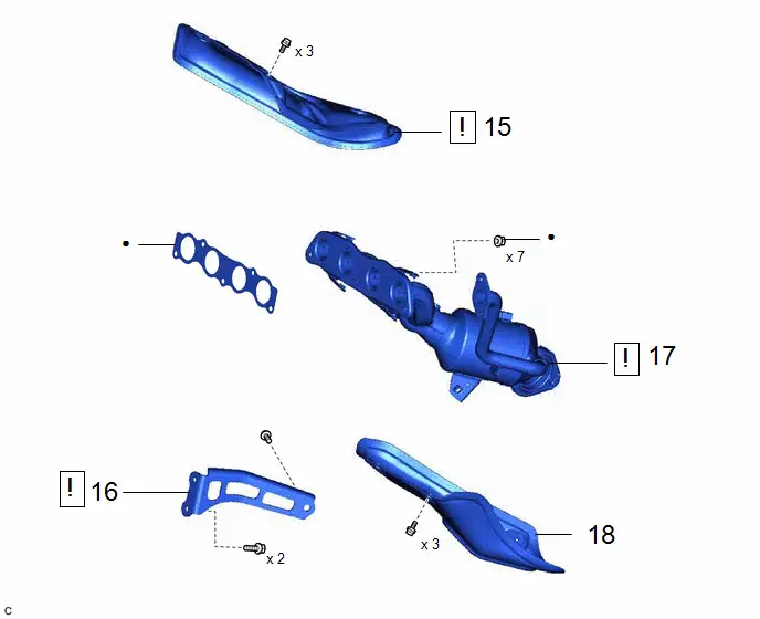
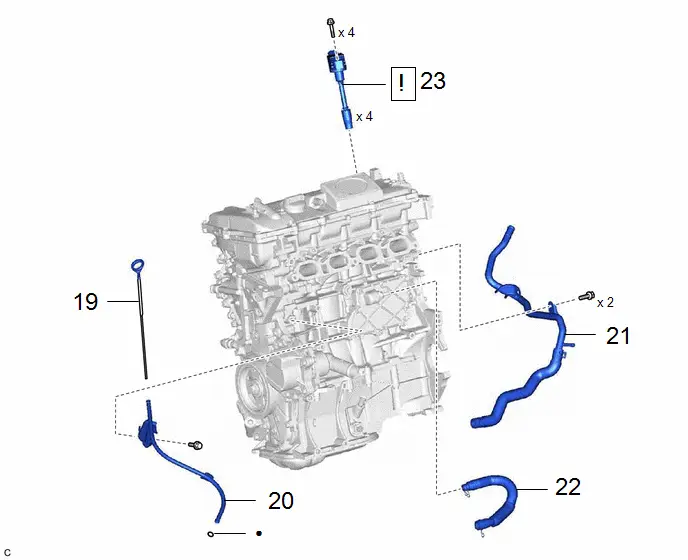
COMPONENTS (REMOVAL)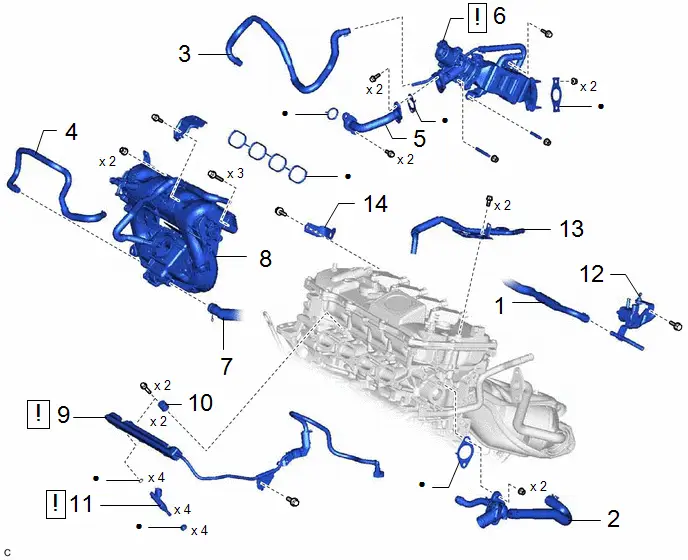
| Procedure | Part Name Code |

|

|

| |
|---|---|---|---|---|---|
| 1 | NO. 8 WATER BY-PASS HOSE | 16296 | - | - | - |
| 2 | WATER OUTLET | 16331 | - | - | - |
| 3 | WATER BY-PASS HOSE | 16261 | - | - | - |
| 4 | NO. 2 WATER BY-PASS HOSE | 16264 | - | - | - |
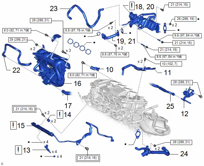
| 5 | EGR PIPE ASSEMBLY | 25610 | - | - | - |
| 6 | EGR VALVE ASSEMBLY WITH EGR COOLER | 25601L |
| - | - |
| 7 | VENTILATION HOSE | 12261 | - | - | - |
| 8 | INTAKE MANIFOLD | 17111 | - | - | - |
| 9 | FUEL DELIVERY PIPE SUB-ASSEMBLY | 23807 |
| - | - |
| 10 | NO. 1 DELIVERY PIPE SPACER | 23807V | - | - | - |
| 11 | FUEL INJECTOR ASSEMBLY | 23250 |
| - | - |
| 12 | PURGE VALVE (PURGE VSV) | 17650G | - | - | - |
| 13 | FUEL VAPOR FEED PIPE | 23818 | - | - | - |
| 14 | WIRE HARNESS CLAMP BRACKET | - | - | - | - |


| ● | Non-reusable part | - | - |
| Procedure | Part Name Code |

|

|

| |
|---|---|---|---|---|---|
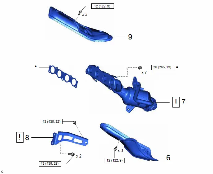
| 15 | NO. 1 EXHAUST MANIFOLD HEAT INSULATOR | 17167 |
| - | - |
| 16 | MANIFOLD STAY | 17118 |
| - | - |
| 17 | EXHAUST MANIFOLD (TWC: Front Catalyst) | 17141 |
| - | - |
| 18 | NO. 2 EXHAUST MANIFOLD HEAT INSULATOR | 17168 | - | - | - |


| ● | Non-reusable part | - | - |
| Procedure | Part Name Code |

|

|

| |
|---|---|---|---|---|---|
| 19 | ENGINE OIL LEVEL DIPSTICK | 15301 | - | - | - |
| 20 | ENGINE OIL LEVEL DIPSTICK GUIDE | 11452 | - | - | - |
| 21 | WATER BY-PASS PIPE | 16268L | - | - | - |
| 22 | VENTILATION HOSE | 12261 | - | - | - |
| 23 | IGNITION COIL ASSEMBLY | 19500 |
| - | - |

| ● | Non-reusable part | - | - |
PROCEDURE
1. REMOVE NO. 8 WATER BY-PASS HOSE

2. REMOVE WATER OUTLET

| *1 | No. 9 Water By-pass Hose | *2 | No. 4 Water By-pass Hose |
3. REMOVE WATER BY-PASS HOSE

4. REMOVE NO. 2 WATER BY-PASS HOSE

5. REMOVE EGR PIPE ASSEMBLY

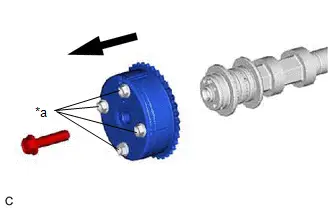
6. REMOVE EGR VALVE ASSEMBLY WITH EGR COOLER
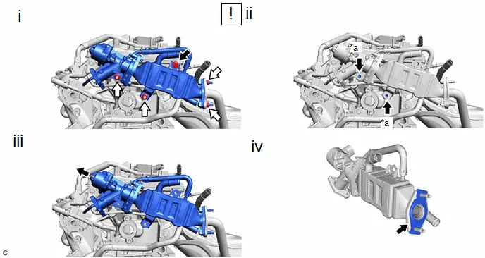
| *a | Stud Bolt | - | - |

| Bolt |

| Nut |
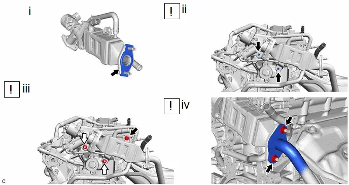
(1) Remove the bolt and 4 nuts.
(2) Using an E8 "TORX" socket wrench, remove the 2 stud bolts and EGR valve assembly with EGR cooler from the cylinder head sub-assembly and exhaust manifold (TWC: Front Catalyst).
(3) Remove the EGR valve assembly with EGR cooler.
(4) Remove the EGR cooler gasket.
7. DISCONNECT VENTILATION HOSE
Click here

8. REMOVE INTAKE MANIFOLD
Click here

9. REMOVE FUEL DELIVERY PIPE SUB-ASSEMBLY

| Click here
|

10. REMOVE NO. 1 DELIVERY PIPE SPACER
Click here

11. REMOVE FUEL INJECTOR ASSEMBLY

| Click here
|

12. REMOVE PURGE VALVE (PURGE VSV)
Click here

13. REMOVE FUEL VAPOR FEED PIPE

14. REMOVE WIRE HARNESS CLAMP BRACKET

15. REMOVE NO. 1 EXHAUST MANIFOLD HEAT INSULATOR

| Click here
|

16. REMOVE MANIFOLD STAY

| Click here
|

17. REMOVE EXHAUST MANIFOLD (TWC: Front Catalyst)

| Click here
|

18. REMOVE NO. 2 EXHAUST MANIFOLD HEAT INSULATOR
Click here

19. REMOVE ENGINE OIL LEVEL DIPSTICK
Click here

20. REMOVE ENGINE OIL LEVEL DIPSTICK GUIDE
Click here

21. REMOVE WATER BY-PASS PIPE

22. REMOVE VENTILATION HOSE

23. REMOVE IGNITION COIL ASSEMBLY

| Click here
|

Disassembly
DISASSEMBLY
CAUTION / NOTICE / HINT
COMPONENTS (DISASSEMBLY)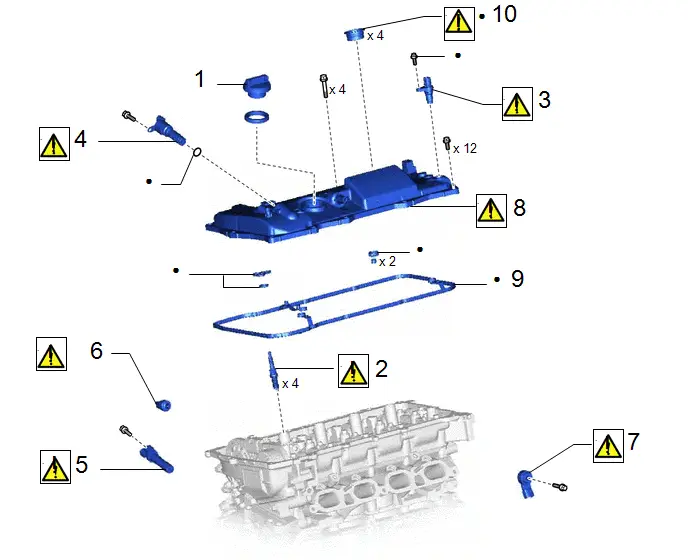
| Procedure | Part Name Code |

|

|

| |
|---|---|---|---|---|---|
| 1 | OIL FILLER CAP SUB-ASSEMBLY | 12108 | - | - | - |
| 2 | SPARK PLUG | 19100P |
| - | - |
| 3 | CAMSHAFT POSITION SENSOR | 11101E |
| - | - |
| 4 | CAMSHAFT TIMING OIL CONTROL VALVE ASSEMBLY | 11101J |
| - | - |
| 5 | CRANKSHAFT POSITION SENSOR | 11401G |
| - | - |
| 6 | ENGINE OIL PRESSURE SWITCH ASSEMBLY | 83530 |
| - | - |
| 7 | KNOCK CONTROL SENSOR | 89615 |
| - | - |
| 8 | CYLINDER HEAD COVER SUB-ASSEMBLY | 11201 |
| - | - |
| 9 | CYLINDER HEAD COVER GASKET | 11213 | - | - | - |
| 10 | SPARK PLUG TUBE GASKET | 11193 |
| - | - |


| ● | Non-reusable part | ★ | Precoated part |
| Procedure | Part Name Code |

|

|

| |
|---|---|---|---|---|---|
| 11 | SET NO. 1 CYLINDER TO TDC (COMPRESSION) | - |
| - | - |
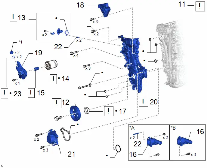
| 12 | CRANKSHAFT PULLEY | 13471 |
| - | - |
| 13 | NO. 1 CHAIN TENSIONER ASSEMBLY | 13540 |
| - | - |
| 14 | OIL FILTER SUB-ASSEMBLY | 15601 |
| - | - |
| 15 | OIL FILTER UNION | 15600A |
| - | - |
| 16 | WATER INLET WITH THERMOSTAT SUB-ASSEMBLY | 16031 | - | - | - |
| 17 | TIMING CHAIN COVER OIL SEAL | 11302A |
| - | - |
| 18 | ENGINE MOUNTING BRACKET RH | 12305 | - | - | - |
| 19 | OIL FILTER BRACKET SUB-ASSEMBLY | 15609 | - | - | - |
| 20 | TIMING CHAIN COVER SUB-ASSEMBLY | 11302 |
| - | - |
| 21 | ENGINE WATER PUMP ASSEMBLY | 16100 | - | - | - |
| 22 | STUD BOLT | - | - | - | - |
| 23 | OIL FILTER BRACKET WITH HEAD STRAIGHT SCREW PLUG GASKET | 15609E |
| - | - |


| *A | Tyep A | *B | Tyep B |
| *1 | OIL FILTER BRACKET WITH HEAD STRAIGHT SCREW PLUG | - | - |
| ● | Non-reusable part | ★ | Precoated part |
| Procedure | Part Name Code |

|

|

| |
|---|---|---|---|---|---|
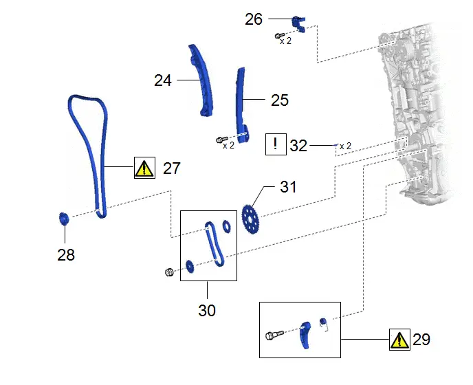
| 24 | CHAIN TENSIONER SLIPPER | 13559 | - | - | - |
| 25 | NO. 1 CHAIN VIBRATION DAMPER | 13561 | - | - | - |
| 26 | NO. 2 CHAIN VIBRATION DAMPER | 13562 | - | - | - |
| 27 | CHAIN SUB-ASSEMBLY | 13506 |
| - | - |
| 28 | CRANKSHAFT TIMING SPROCKET | 13521 | - | - | - |
| 29 | CHAIN TENSIONER PLATE | 13549 |
| - | - |
| 30 | NO. 2 CHAIN SUB-ASSEMBLY | 13507 | - | - | - |
| 31 | NO. 1 CRANKSHAFT POSITION SENSOR PLATE | 19315 | - | - | - |
| 32 | CRANKSHAFT TIMING GEAR KEY | 13521A | - | - | - |


| Procedure | Part Name Code |

|

|

| |
|---|---|---|---|---|---|
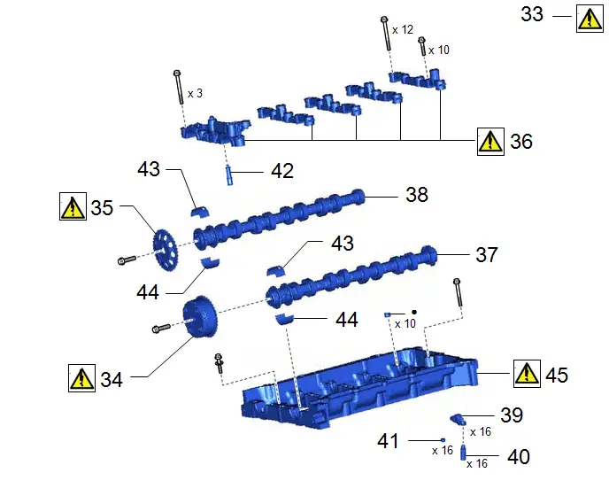
| 33 | INSPECT CAMSHAFT TIMING GEAR ASSEMBLY | 13050 |
| - | - |
| 34 | CAMSHAFT TIMING GEAR ASSEMBLY | 13050 |
| - | - |
| 35 | CAMSHAFT TIMING SPROCKET | - |
| - | - |
| 36 | CAMSHAFT BEARING CAP | - |
| - | - |
| 37 | CAMSHAFT | 13511 | - | - | - |
| 38 | NO. 2 CAMSHAFT | 13512 | - | - | - |
| 39 | NO. 1 VALVE ROCKER ARM SUB-ASSEMBLY | 13801 | - | - | - |
| 40 | VALVE LASH ADJUSTER ASSEMBLY | 13750 | - | - | - |
| 41 | VALVE STEM CAP | 13716 | - | - | - |
| 42 | OIL CONTROL VALVE FILTER | 15678A | - | - | - |
| 43 | NO. 1 CAMSHAFT BEARING | - | - | - | - |
| 44 | NO. 2 CAMSHAFT BEARING | - | - | - | - |
| 45 | CAMSHAFT HOUSING SUB-ASSEMBLY | 11103 |
| - | - |


| ● | Non-reusable part | - | - |
| Procedure | Part Name Code |

|

|

| |
|---|---|---|---|---|---|
| 46 | CYLINDER HEAD SUB-ASSEMBLY | 11101 |
| - | - |
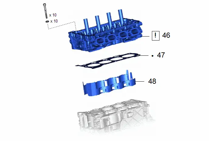
| 47 | CYLINDER HEAD GASKET | 11115 | - | - | - |
| 48 | CYLINDER BLOCK WATER JACKET SPACER | 11445 | - | - | - |

| ● | Non-reusable part | - | - |
| Procedure | Part Name Code |

|

|

| |
|---|---|---|---|---|---|
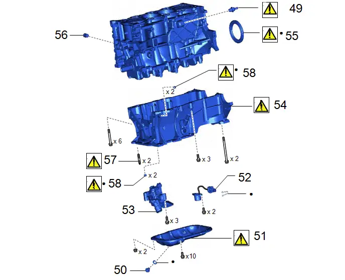
| 49 | PCV VALVE (VENTILATION VALVE SUB-ASSEMBLY) | 12204 |
| - | - |
| 50 | OIL PAN DRAIN PLUG | 12101A | - | - | - |
| 51 | NO. 2 OIL PAN SUB-ASSEMBLY | 12102A |
| - | - |
| 52 | ENGINE OIL LEVEL SENSOR | 89491 | - | - | - |
| 53 | OIL PUMP ASSEMBLY | 15100 | - | - | - |
| 54 | STIFFENING CRANKCASE ASSEMBLY | 11420 |
| - | - |
| 55 | REAR ENGINE OIL SEAL | 11401L |
| - | - |
| 56 | NO. 1 TAPER SCREW PLUG | 11432A | - | - | - |
| 57 | STUD BOLT | - |
| - | - |
| 58 | RING PIN | - |
| - | - |


| ● | Non-reusable part | ★ | Precoated part |
PROCEDURE
1. REMOVE OIL FILLER CAP SUB-ASSEMBLY
2. REMOVE SPARK PLUG

| Click here
|

3. REMOVE CAMSHAFT POSITION SENSOR

| Click here
|

4. REMOVE CAMSHAFT TIMING OIL CONTROL VALVE ASSEMBLY

| Click here
|

5. REMOVE CRANKSHAFT POSITION SENSOR

| Click here
|

6. REMOVE ENGINE OIL PRESSURE SWITCH ASSEMBLY

| Click here
|

7. REMOVE KNOCK CONTROL SENSOR

| Click here
|

8. REMOVE CYLINDER HEAD COVER SUB-ASSEMBLY
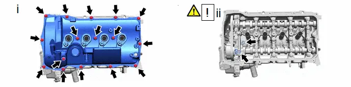
(1) Remove the 16 bolts and cylinder head cover sub-assembly from the camshaft housing sub-assembly.
(2) Remove the 2 gaskets from the camshaft bearing cap.
NOTICE:
As the gaskets may stick to the cylinder head cover sub-assembly, be careful not to drop any of the gaskets into the engine when removing the cylinder head cover sub-assembly.
9. REMOVE CYLINDER HEAD COVER GASKET

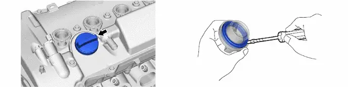
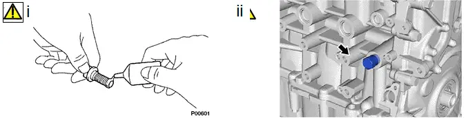
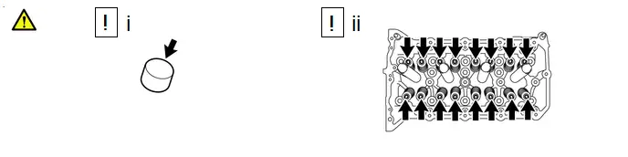
10. REMOVE SPARK PLUG TUBE GASKET

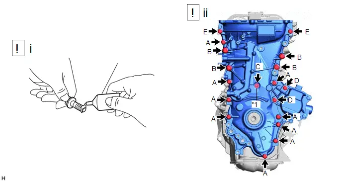
(1) Using a screwdriver as shown in the illustration, deform each spark plug tube gasket inwards and remove the 4 spark plug tube gaskets from the cylinder head cover sub-assembly.
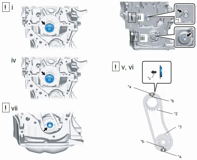
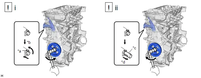
11. SET NO. 1 CYLINDER TO TDC (COMPRESSION)
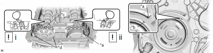
| *a | Timing Mark | *b | Timing Notch |
| *c | Timing Mark (Rectangle) | *d | Mark (Circle) |
(1) Turn the crankshaft pulley until its timing notch is aligned with timing mark "0" of the timing chain cover sub-assembly.
HINT:
There are 3 marks on the camshaft timing sprocket. Make sure that the timing mark (rectangle) is at the top.
(2) Check that the timing marks on both the camshaft timing sprocket and camshaft timing gear assembly are facing upward as shown in the illustration.
HINT:
If not, turn the crankshaft 1 complete revolution (360°) and align the timing marks as shown in the illustration.
12. REMOVE CRANKSHAFT PULLEY

| Click here
|

13. REMOVE NO. 1 CHAIN TENSIONER ASSEMBLY

| NOTICE: Do not turn the crankshaft without the No. 1 chain tensioner assembly installed. |

14. REMOVE OIL FILTER SUB-ASSEMBLY

| Click here
|

15. REMOVE OIL FILTER UNION

(1) Using a 12 mm hexagon socket wrench, remove the oil filter union from the oil filter bracket sub-assembly.
16. REMOVE WATER INLET WITH THERMOSTAT SUB-ASSEMBLY
Click here

17. REMOVE TIMING CHAIN COVER OIL SEAL

| Click here
|

18. REMOVE ENGINE MOUNTING BRACKET RH

19. REMOVE OIL FILTER BRACKET SUB-ASSEMBLY
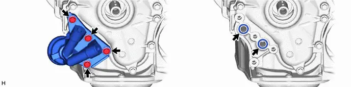
20. REMOVE TIMING CHAIN COVER SUB-ASSEMBLY
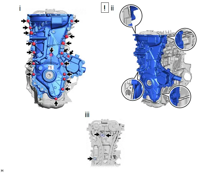
| *1 | Seal Washer | - | - |
(1) Remove the 18 bolts and seal washer from the timing chain cover sub-assembly.
(2) Remove the timing chain cover sub-assembly by prying between the timing chain cover sub-assembly and cylinder head sub-assembly, camshaft housing sub-assembly, cylinder block sub-assembly and stiffening crankcase assembly with a screwdriver with its tip wrapped with protective tape.
NOTICE:
Be careful not to damage the contact surfaces of the cylinder head sub-assembly, camshaft housing sub-assembly, cylinder block sub-assembly, stiffening crankcase assembly and timing chain cover sub-assembly.
(3) Remove the 3 O-rings from the cylinder head sub-assembly and cylinder block sub-assembly.
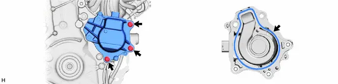
21. REMOVE ENGINE WATER PUMP ASSEMBLY
22. REMOVE STUD BOLT
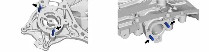
23. REMOVE OIL FILTER BRACKET WITH HEAD STRAIGHT SCREW PLUG GASKET

(1) Using a 10 mm hexagon socket wrench, remove the 2 oil filter bracket with head straight screw plugs and 2 oil filter bracket with head straight screw plug gaskets from the oil filter bracket.
24. REMOVE CHAIN TENSIONER SLIPPER

25. REMOVE NO. 1 CHAIN VIBRATION DAMPER

26. REMOVE NO. 2 CHAIN VIBRATION DAMPER

27. REMOVE CHAIN SUB-ASSEMBLY

| Click here
|

28. REMOVE CRANKSHAFT TIMING SPROCKET

29. REMOVE CHAIN TENSIONER PLATE
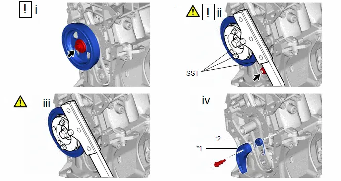
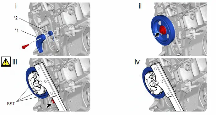
| *1 | Chain Tensioner Plate | *2 | Chain Damper Spring |
(1) Temporarily install the crankshaft pulley with the crankshaft pulley set bolt.
(2) Using SST, hold the crankshaft pulley. Then remove the oil pump drive shaft gear nut.
SST: 09213-58014
91551-80840
SST: 09330-00021
(3) Remove SST, the crankshaft pulley set bolt and crankshaft pulley.
(4) Remove the bolt, chain tensioner plate and chain damper spring.
30. REMOVE NO. 2 CHAIN SUB-ASSEMBLY
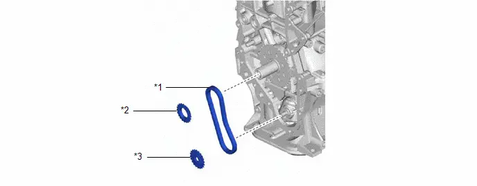
| *1 | No. 2 Chain Sub-assembly | *2 | Oil Pump Drive Gear |
| *3 | Oil Pump Drive Shaft Gear | - | - |
31. REMOVE NO. 1 CRANKSHAFT POSITION SENSOR PLATE

32. REMOVE CRANKSHAFT TIMING GEAR KEY

(1) Using a screwdriver with its tip wrapped with protective tape, remove the 2 crankshaft timing gear keys from the crankshaft.
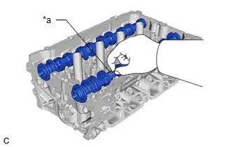
33. INSPECT CAMSHAFT TIMING GEAR ASSEMBLY
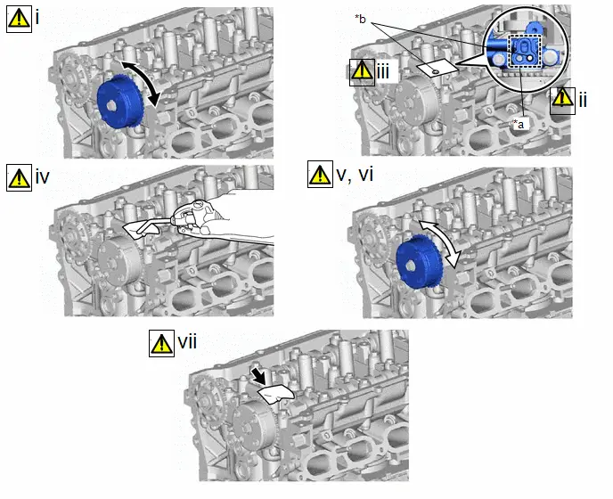
| *a | Adhesive Tape Sealing Area | *b | Prick a hole |

| Lock | - | - |
(1) Check the lock of the camshaft timing gear assembly.
(2) After cleaning the oil hole in the intake side of the No. 1 camshaft bearing cap, completely seal the oil hole with adhesive tape or equivalent as shown in the illustration to prevent air from leaking.
NOTICE:
Be sure to cover the oil hole completely because air leaks due to insufficient sealing will prevent the lock pin from being released.
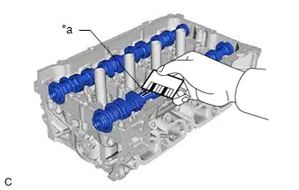
(3) Prick a hole in the tape covering the oil hole as shown in the illustration. (Procedure A)
(4) Apply approximately 150 kPa (1.5 kgf/cm2, 22 psi) of air pressure to the hole pricked in procedure A to release the lock pin.
NOTICE:
- If air leaks out, reattach the adhesive tape.
- Cover the oil hole with a piece of cloth when applying air pressure to prevent oil from spraying.
(5) Forcibly turn the camshaft timing gear assembly in the advance direction (counterclockwise).
HINT:
Depending on the air pressure applied, the camshaft timing gear assembly may turn in the advance direction without assistance.
(6) Turn the camshaft timing gear assembly within its movable range (30 to 32°) 2 or 3 times without turning it to the most retarded position. Make sure that the camshaft timing gear assembly turns smoothly.
NOTICE:
- Do not lock the camshaft timing gear assembly.
- If camshaft timing gear assembly is locked, release the lock pin again.
(7) Remove the adhesive tape from the No. 1 camshaft bearing cap.
34. REMOVE CAMSHAFT TIMING GEAR ASSEMBLY

(1) Using a wrench to hold the hexagonal portion of the camshaft, remove the bolt and camshaft timing gear assembly.
NOTICE:
- Before removing the camshaft timing gear assembly, make sure that the lock pin has been released.
- Be sure not to remove the other 4 bolts.
- Keep the camshaft timing gear assembly horizontal while removing it from the camshaft.
| *a | Do not remove |
35. REMOVE CAMSHAFT TIMING SPROCKET

(1) Using a wrench to hold the hexagonal portion of the No. 2 camshaft, remove the bolt and camshaft timing sprocket.
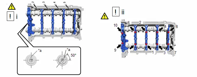
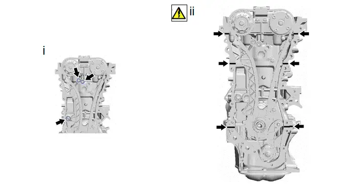
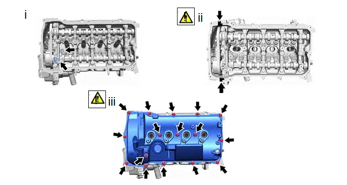
36. REMOVE CAMSHAFT BEARING CAP
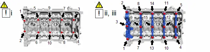
(1) Uniformly loosen and remove the 10 bolts in the order shown in the illustration.
(2) Uniformly loosen and remove the 15 bolts in the order shown in the illustration.
NOTICE:
Make sure that the camshaft and No. 2 camshaft remain level while uniformly loosening the bolts.
(3) Remove the 5 camshaft bearing caps.
HINT:
Arrange the removed parts in such a way that they can be reinstalled to their original locations.
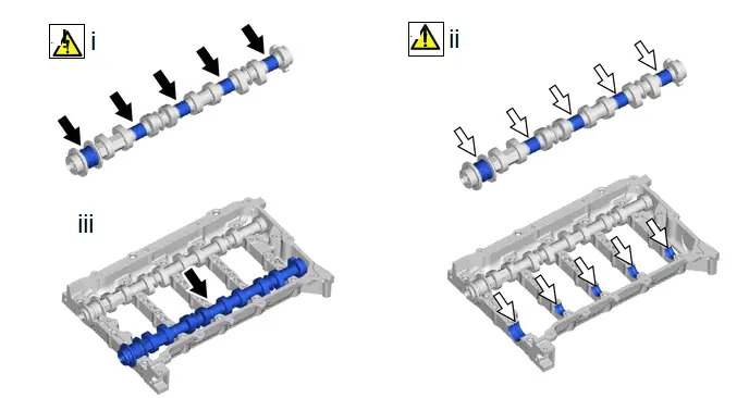
37. REMOVE CAMSHAFT

38. REMOVE NO. 2 CAMSHAFT
Click here

39. REMOVE NO. 1 VALVE ROCKER ARM SUB-ASSEMBLY

40. REMOVE VALVE LASH ADJUSTER ASSEMBLY

41. REMOVE VALVE STEM CAP

42. REMOVE OIL CONTROL VALVE FILTER

43. REMOVE NO. 1 CAMSHAFT BEARING

44. REMOVE NO. 2 CAMSHAFT BEARING

45. REMOVE CAMSHAFT HOUSING SUB-ASSEMBLY
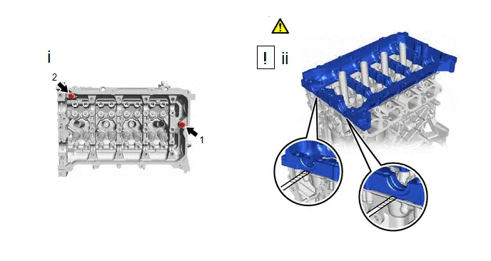
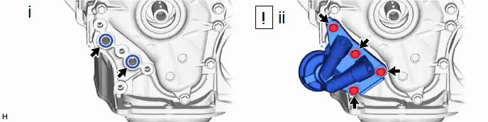
(1) Remove the 2 bolts from the camshaft housing sub-assembly.
(2) Remove the camshaft housing sub-assembly by prying between the cylinder head sub-assembly and camshaft housing sub-assembly with a screwdriver with its tip wrapped with protective tape.
NOTICE:
Be careful not to damage the contact surfaces of the cylinder head sub-assembly and camshaft housing sub-assembly.
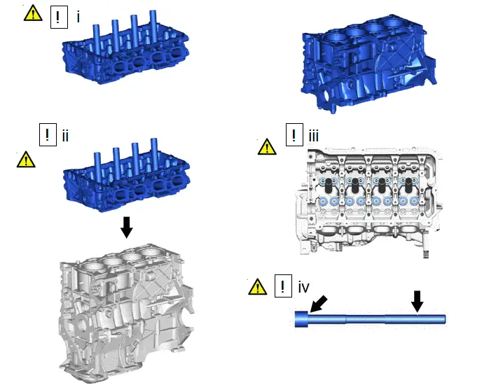
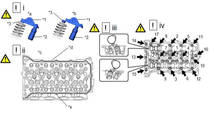
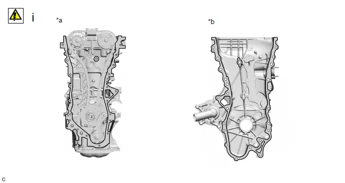
46. REMOVE CYLINDER HEAD SUB-ASSEMBLY
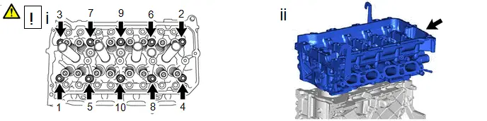
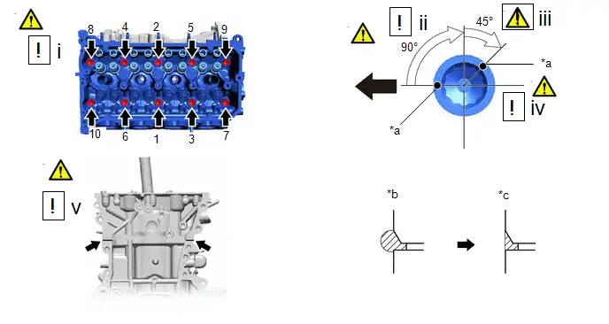
(1) Using a 10 mm bi-hexagon socket wrench, uniformly loosen and remove the 10 cylinder head set bolts and 10 cylinder head set plate washers in several steps in the order shown in the illustration.
NOTICE:
- Do not drop the cylinder head set plate washers into the cylinder head sub-assembly.
- Removing the cylinder head set bolts in the incorrect order may cause warpage or cracking of the cylinder head sub-assembly.
HINT:
Arrange the removed parts in such a way that they can be reinstalled to their original locations.
(2) Remove the cylinder head sub-assembly from the cylinder block sub-assembly.
47. REMOVE CYLINDER HEAD GASKET
Click here

48. REMOVE CYLINDER BLOCK WATER JACKET SPACER
49. REMOVE PCV VALVE (VENTILATION VALVE SUB-ASSEMBLY)

| Click here
|

50. REMOVE OIL PAN DRAIN PLUG

51. REMOVE NO. 2 OIL PAN SUB-ASSEMBLY
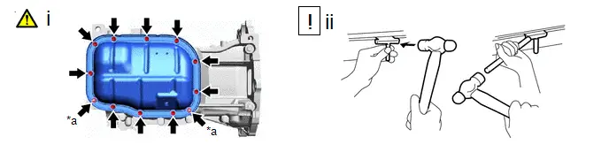
| *a | Nut | - | - |
(1) Remove the 10 bolts and 2 nuts from the No. 2 oil pan sub-assembly.
(2) Insert the blade of an oil pan seal cutter between the stiffening crankcase assembly and No. 2 oil pan sub-assembly. Cut through the applied sealer and remove the No. 2 oil pan sub-assembly.
NOTICE:
- Be careful not to damage the surface of the No. 2 oil pan sub-assembly which contacts the stiffening crankcase assembly.
- Be careful not to damage the flange of the stiffening crankcase assembly.
52. REMOVE ENGINE OIL LEVEL SENSOR
Click here

53. REMOVE OIL PUMP ASSEMBLY
Click here

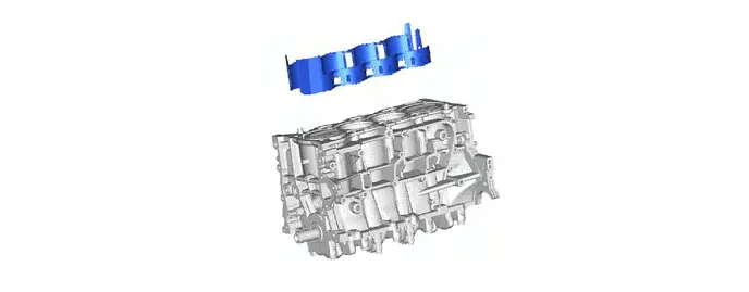
54. REMOVE STIFFENING CRANKCASE ASSEMBLY
(1) Uniformly loosen and remove the 11 bolts from the stiffening crankcase assembly.
(2) Remove the stiffening crankcase assembly by prying between the stiffening crankcase assembly and cylinder block sub-assembly with a screwdriver with its tip wrapped with protective tape.
NOTICE:
Be careful not to damage the contact surfaces of the stiffening crankcase assembly and cylinder block sub-assembly.
55. REMOVE REAR ENGINE OIL SEAL

| NOTICE: Be careful not to damage the crankshaft. |

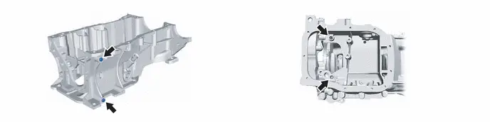
56. REMOVE NO. 1 TAPER SCREW PLUG

57. REMOVE STUD BOLT

| NOTICE: If a stud bolt is deformed or its threads are damaged, replace it. |

58. REMOVE RING PIN

| NOTICE: It is not necessary to remove ring pins unless they are being replaced. |
Inspection
INSPECTION
PROCEDURE
1. INSPECT NO. 1 VALVE ROCKER ARM SUB-ASSEMBLY
| (a) Turn the roller by hand to check that it turns smoothly. |
|
(b) If the roller does not turn smoothly, replace the No. 1 valve rocker arm sub-assembly.
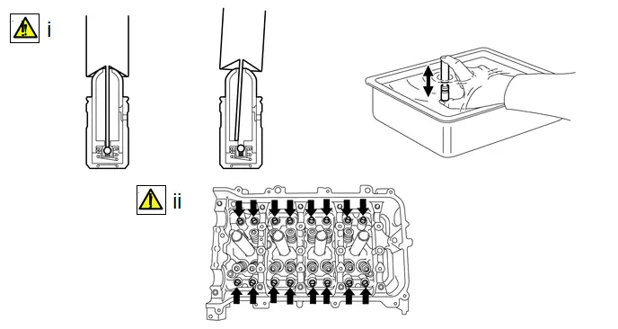
2. INSPECT VALVE LASH ADJUSTER ASSEMBLY
NOTICE:
- Keep the valve lash adjuster assembly free from dirt and foreign matter.
- Only use clean engine oil.
Pre-procedure1
(a) Place the valve lash adjuster assembly into a container filled with engine oil.
(b) Insert the tip of SST into the valve lash adjuster assembly plunger and use the tip to press down on the check ball inside the plunger.
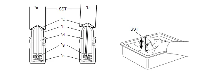
| *a | Correct | *b | Incorrect |
| *c | Taper | *d | Low Pressure Chamber |
| *e | High Pressure Chamber | *f | Plunger |
| *g | Check Ball | - | - |
SST: 09276-75010
(c) Squeeze SST and the valve lash adjuster assembly together to move the plunger up and down 5 to 6 times.
Procedure1
(d) Check the movement of the plunger and bleed the air.
OK:
Plunger moves up and down.
NOTICE:
When bleeding air from the high-pressure chamber, make sure that the tip of SST is actually pressing the check ball as shown in the illustration. If the check ball is not pressed, air will not bleed.
Procedure2
(e) After bleeding the air, remove SST. Then try to quickly and firmly press the plunger by hand.
OK:
Plunger is very difficult to move.
(f) If the plunger is easy to move, replace the valve lash adjuster assembly.
Post-procedure1
(g) None
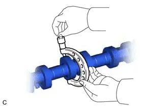
3. INSPECT CHAIN SUB-ASSEMBLY
Pre-procedure1
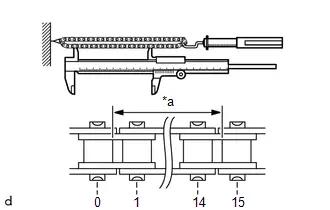
| (a) Using a spring scale, pull the chain sub-assembly with a force of 147 N (15 kgf, 33.0 lbf) as shown in the illustration. |
|

Procedure1
(b) Using a vernier caliper, measure the length of 15 links.
Maximum Chain Elongation:
| Specified Condition | Result |
|---|---|
| 115.2 mm 4.54 in. | mm in. |
NOTICE:
Perform the measurement at 3 random places. Use the average of the measurements.
(c) If the average elongation is more than the maximum, replace the chain sub-assembly.
Post-procedure1
(d) None
4. INSPECT NO. 2 CHAIN SUB-ASSEMBLY
Pre-procedure1
| (a) Using a spring scale, pull the No. 2 chain sub-assembly with a force of 147 N (15 kgf, 33.0 lbf) as shown in the illustration. |
|
Procedure1
(b) Using a vernier caliper, measure the length of 15 links.
Maximum Chain Elongation:
| Specified Condition | Result |
|---|---|
| 102.1 mm 4.02 in. | mm in. |
NOTICE:
Perform the measurement at 3 random places. Use the average of the measurements.
(c) If the average elongation is more than the maximum, replace the No. 2 chain sub-assembly.
Post-procedure1
(d) None
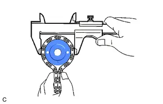
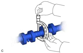
5. INSPECT OIL PUMP DRIVE GEAR
Pre-procedure1
| (a) Place the No. 2 chain sub-assembly around the oil pump drive gear. |
|
Procedure1
(b) Using a vernier caliper, measure the diameter of the oil pump drive gear and No. 2 chain sub-assembly.
Minimum Gear Diameter (with No. 2 Chain Sub-assembly):
| Specified Condition | Result |
|---|---|
| 48.2 mm 1.90 in. | mm in. |
NOTICE:
The vernier caliper must be in contact with the chain rollers when measuring.
(c) If the diameter is less than the minimum, replace the No. 2 chain sub-assembly and oil pump drive gear.
Post-procedure1
(d) None
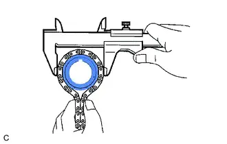
6. INSPECT OIL PUMP DRIVE SHAFT GEAR
Pre-procedure1
| (a) Place the No. 2 chain sub-assembly around the oil pump drive shaft gear. |
|
Procedure1
(b) Using a vernier caliper, measure the diameter of the oil pump drive shaft gear and No. 2 chain sub-assembly.
Minimum Gear Diameter (with No. 2 Chain Sub-assembly):
| Specified Condition | Result |
|---|---|
| 48.2 mm 1.90 in. | mm in. |
NOTICE:
The vernier caliper must be in contact with the chain rollers when measuring.
(c) If the diameter is less than the minimum, replace the No. 2 chain sub-assembly and oil pump drive shaft gear.
Post-procedure1
(d) None
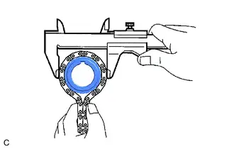
7. INSPECT CAMSHAFT TIMING GEAR ASSEMBLY
Pre-procedure1
| (a) Place the chain sub-assembly around the camshaft timing gear assembly. |
|
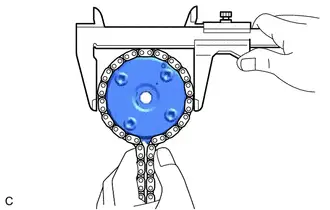
Procedure1
(b) Using a vernier caliper, measure the diameter of the camshaft timing gear assembly and chain sub-assembly.
Minimum Gear Diameter (with Chain Sub-assembly):
| Specified Condition | Result |
|---|---|
| 96.8 mm 3.81 in. | mm in. |
NOTICE:
The vernier caliper must be in contact with the chain rollers when measuring.
(c) If the diameter is less than the minimum, replace the chain sub-assembly and camshaft timing gear assembly.
Post-procedure1
(d) None
8. INSPECT CAMSHAFT TIMING SPROCKET
Pre-procedure1
| (a) Place the chain sub-assembly around the camshaft timing sprocket. |
|
Procedure1
(b) Using a vernier caliper, measure the diameter of the camshaft timing sprocket and chain sub-assembly.
Minimum Gear Diameter (with Chain Sub-assembly):
| Specified Condition | Result |
|---|---|
| 96.8 mm 3.81 in. | mm in. |
NOTICE:
The vernier caliper must be in contact with the chain rollers when measuring.
(c) If the diameter is less than the minimum, replace the chain sub-assembly and camshaft timing sprocket.
Post-procedure1
(d) None
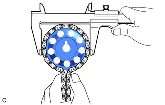
9. INSPECT CRANKSHAFT TIMING GEAR OR SPROCKET
Pre-procedure1
| (a) Place the chain sub-assembly around the crankshaft timing sprocket. |
|
Procedure1
(b) Using a vernier caliper, measure the diameter of the crankshaft timing sprocket and chain sub-assembly.
Minimum Sprocket Diameter (with Chain Sub-assembly):
| Specified Condition | Result |
|---|---|
| 51.1 mm 2.01 in. | mm in. |
NOTICE:
The vernier caliper must be in contact with the chain rollers when measuring.
(c) If the diameter is less than the minimum, replace the chain sub-assembly and crankshaft timing sprocket.
Post-procedure1
(d) None
10. INSPECT CHAIN TENSIONER SLIPPER
| (a) Using a vernier caliper, measure the wear depth of the chain tensioner slipper. Maximum Depth:
|
|
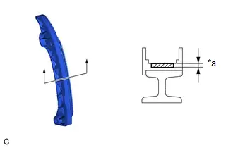
(b) If the depth is more than the maximum, replace the chain tensioner slipper.
11. INSPECT NO. 1 CHAIN VIBRATION DAMPER
| (a) Using a vernier caliper, measure the wear depth of the No. 1 chain vibration damper. Maximum Depth:
|
|
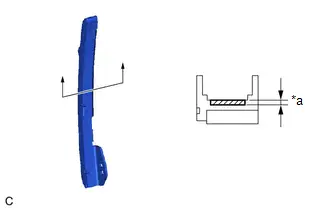
(b) If the depth is more than the maximum, replace the No. 1 chain vibration damper.
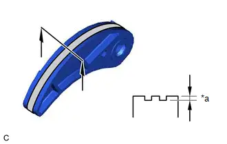
12. INSPECT NO. 2 CHAIN VIBRATION DAMPER
| (a) Using a vernier caliper, measure the wear depth of the No. 2 chain vibration damper. Maximum Depth:
|
|
(b) If the depth is more than the maximum, replace the No. 2 chain vibration damper.
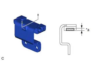
13. INSPECT CHAIN TENSIONER PLATE
| (a) Using a vernier caliper, measure the wear depth of the chain tensioner plate. Maximum Depth:
|
|
(b) If the depth is more than the maximum, replace the chain tensioner plate.
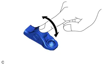
14. INSPECT NO. 1 CHAIN TENSIONER ASSEMBLY
| (a) Check that the plunger moves smoothly when the cam is raised with your finger. |
|
(b) Release the cam, then check that the plunger is locked in place by the cam and does not move when pushed with your finger.
(c) If the plunger does not move smoothly, replace the No. 1 chain tensioner assembly.
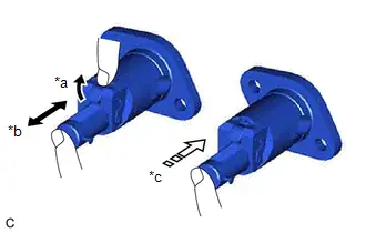
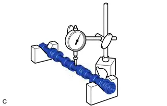
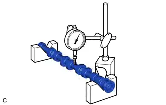
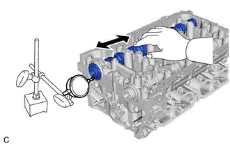
15. INSPECT CAMSHAFT
| (a) Inspect the camshaft for runout. (1) Place the camshaft on V-blocks. (2) Using a dial indicator, measure the runout at the center journal. Maximum Runout:
(3) If the runout is more than the maximum, replace the camshaft. |
|
| (b) Inspect the cam lobes. (1) Using a micrometer, measure the cam lobe height. Standard Cam Lobe Height:
(2) If the cam lobe height is less than the minimum, replace the camshaft. |
|
| (c) Inspect the camshaft journals. (1) Using a micrometer, measure the journal diameter. Standard Journal Diameter:
(2) If the journal diameter is not as specified, check the camshaft oil clearance. Click here
|
|

16. INSPECT NO. 2 CAMSHAFT
| (a) Inspect the No. 2 camshaft for runout. (1) Place the No. 2 camshaft on V-blocks. (2) Using a dial indicator, measure the runout at the center journal. Maximum Runout:
(3) If the runout is more than the maximum, replace the No. 2 camshaft. |
|
| (b) Inspect the cam lobes. (1) Using a micrometer, measure the cam lobe height. Standard Cam Lobe Height:
(2) If the cam lobe height is less than the minimum, replace the No. 2 camshaft. |
|
| (c) Inspect the No. 2 camshaft journals. (1) Using a micrometer, measure the journal diameter. Standard Journal Diameter:
(2) If the journal diameter is not as specified, check the No. 2 camshaft oil clearance. HINT: Click here
|
|

17. INSPECT CYLINDER HEAD SET BOLT
| (a) Using a vernier caliper, measure the length of the cylinder head set bolt from the seat to the end. Standard Length:
(1) If the length is greater than the maximum, replace the cylinder head set bolt with a new one. Failure to do so may lead to engine damage. (2) If there is any thread deformation, replace the cylinder head set bolt with a new one. |
|
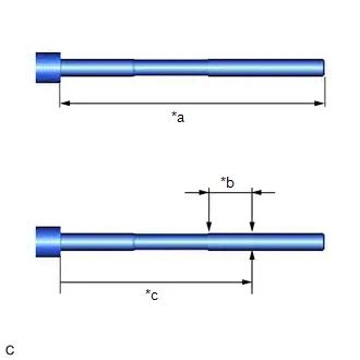
(b) Using a vernier caliper, measure the diameter of the threads at several points within the area shown in the illustration.
Standard Diameter:
| Measurement Point (Distance from the Seat) | Minimum Diameter | Specified Condition | Result |
|---|---|---|---|
| 115 mm 4.53 in. | 9.4 mm 0.370 in. | 9.77 to 9.96 mm 0.385 to 0.392 in. | mm in. |
NOTICE:
Diameter measurements should be done at several points.
(1) If the diameter is less than the minimum, replace the cylinder head set bolt with a new one. Failure to do so may lead to engine damage.
(2) If there is any thread deformation, replace the cylinder head set bolt with a new one.
18. INSPECT CAMSHAFT THRUST CLEARANCE
Pre-procedure1
(a) Clean the camshaft, No. 2 camshaft and camshaft bearing caps.
(b) Place the camshaft, No. 2 camshaft and camshaft housing sub-assembly on the cylinder head sub-assembly.
(c) Install the camshaft bearing caps.
HINT:
Click here

(d) Install the camshaft housing sub-assembly.
HINT:
Click here

Procedure1
| (e) Using a dial indicator, measure the thrust clearance while moving the camshaft and No. 2 camshaft back and forth. Standard Thrust Clearance:
|
|
(f) If the thrust clearance is more than the maximum, replace the camshaft housing sub-assembly. If the thrust surface is damaged, replace the camshaft.
Post-procedure1
(g) None
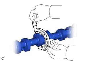
19. INSPECT CAMSHAFT OIL CLEARANCE
Pre-procedure1
(a) Clean the camshaft bearing caps and camshaft journals.
(b) Place the camshaft, No. 2 camshaft and camshaft housing sub-assembly on the cylinder head sub-assembly.
| (c) Lay a strip of Plastigage across each of the camshaft journals. |
|
(d) Install the camshaft bearing caps.
NOTICE:
Do not turn the camshaft.
HINT:
Click here

(e) Remove the camshaft bearing caps.
HINT:
Click here

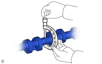
Procedure1
| (f) Measure the Plastigage at its widest point. Standard Oil Clearance:
NOTICE: Completely remove the Plastigage after the inspection. |
|
(g) If the oil clearance is greater than the maximum, replace the camshaft or No. 2 camshaft. If necessary, replace the cylinder head sub-assembly.
Post-procedure1
(h) None
20. INSPECT EXHAUST MANIFOLD (TWC: Front Catalyst)
| (a) Using a precision straightedge and feeler gauge, check the surface that contacts the cylinder head sub-assembly for warpage. Maximum Warpage:
|
|
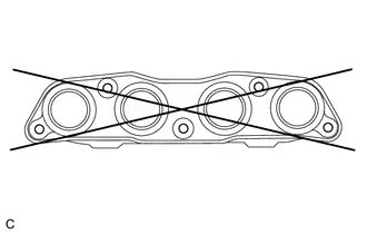
(b) If the warpage is more than the maximum, replace the exhaust manifold (TWC: Front Catalyst).
Reassembly
REASSEMBLY
CAUTION / NOTICE / HINT
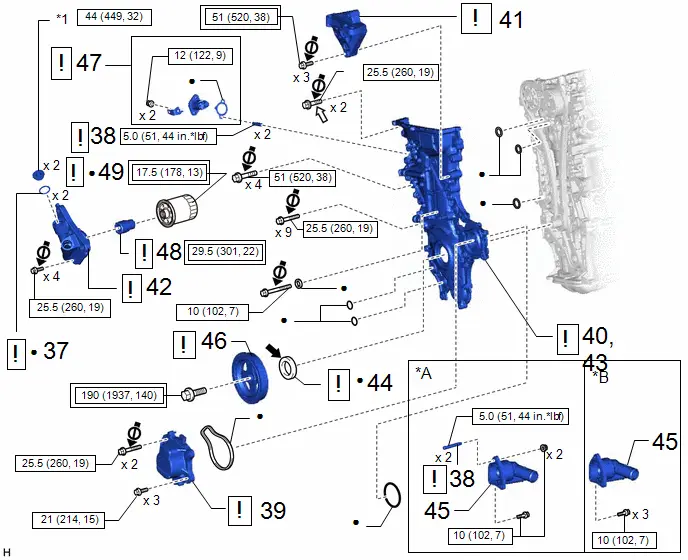
COMPONENTS (REASSEMBLY)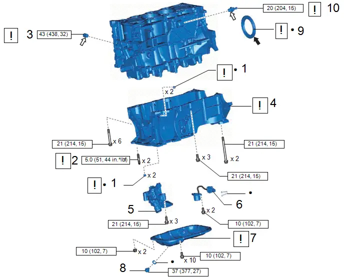
| Procedure | Part Name Code |

|

|

| |
|---|---|---|---|---|---|
| 1 | RING PIN | - |
| - | - |
| 2 | STUD BOLT | - |
| - | - |
| 3 | NO. 1 TAPER SCREW PLUG | 11432A |
| - | - |
| 4 | STIFFENING CRANKCASE ASSEMBLY | 11420 |
| - | - |
| 5 | OIL PUMP ASSEMBLY | 15100 | - | - | - |
| 6 | ENGINE OIL LEVEL SENSOR | 89491 | - | - | - |
| 7 | NO. 2 OIL PAN SUB-ASSEMBLY | 12102A |
| - | - |
| 8 | OIL PAN DRAIN PLUG | 12101A | - | - | - |
| 9 | REAR ENGINE OIL SEAL | 11401L |
| - | - |
| 10 | PCV VALVE (VENTILATION VALVE SUB-ASSEMBLY) | 12204 |
| - | - |


| N*m (kgf*cm, ft.*lbf): Specified torque | ● | Non-reusable part |

| MP grease |

| Adhesive 1324 |
| ★ | Procoated part | - | - |
| Procedure | Part Name Code |

|

|

| |
|---|---|---|---|---|---|
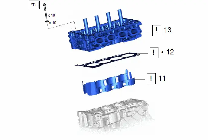
| 11 | CYLINDER BLOCK WATER JACKET SPACER | 11445 |
| - | - |
| 12 | CYLINDER HEAD GASKET | 11115 |
| - | - |
| 13 | CYLINDER HEAD SUB-ASSEMBLY | 11101 |
| - | - |


| Tightening torque for "Major areas involving basic Toyota Prius vehicle performance such as moving/turning/stopping": N*m (kgf*cm, ft.*lbf) | ● | Non-reusable part |
| *T1 | 1st: 49 (500, 36) 2nd: Turn 90° 3rd: Turn 45° | - | - |
| Procedure | Part Name Code |

|

|

| |
|---|---|---|---|---|---|
| 14 | VALVE STEM CAP | 13716 |
| - | - |
| 15 | VALVE LASH ADJUSTER ASSEMBLY | 13750 |
| - | - |
| 16 | NO. 1 VALVE ROCKER ARM SUB-ASSEMBLY | 13801 |
| - | - |
| 17 | RING PIN | - |
| - | - |
| 18 | NO. 1 CAMSHAFT BEARING | - |
| - | - |
| 19 | NO. 2 CAMSHAFT BEARING | - |
| - | - |
| 20 | OIL CONTROL VALVE FILTER | 15678A |
| - | - |
| 21 | NO. 2 CAMSHAFT | 13512 |
| - | - |
| 22 | CAMSHAFT | 13511 |
| - | - |
| 23 | CAMSHAFT BEARING CAP | - |
| - | - |
| 24 | CAMSHAFT HOUSING SUB-ASSEMBLY | 11103 |
| - | - |
| 25 | CAMSHAFT TIMING SPROCKET | - |
| - | - |
| 26 | CAMSHAFT TIMING GEAR ASSEMBLY | 13050 |
| - | - |


| N*m (kgf*cm, ft.*lbf): Specified torque | ● | Non-reusable part |
| Procedure | Part Name Code |

|

|

| |
|---|---|---|---|---|---|
| 27 | CRANKSHAFT TIMING GEAR KEY | 13521A |
| - | - |
| 28 | NO. 1 CRANKSHAFT POSITION SENSOR PLATE | 19315 |
| - | - |
| 29 | NO. 2 CHAIN SUB-ASSEMBLY | 13507 |
| - | - |
| 30 | CHAIN TENSIONER PLATE | 13549 |
| - | - |
| 31 | CRANKSHAFT TIMING SPROCKET | 13521 | - | - | - |
| 32 | SET NO. 1 CYLINDER TO TDC (COMPRESSION) | - |
| - | - |
| 33 | NO. 1 CHAIN VIBRATION DAMPER | 13561 | - | - | - |
| 34 | CHAIN SUB-ASSEMBLY | 13506 |
| - | - |
| 35 | NO. 2 CHAIN VIBRATION DAMPER | 13562 | - | - | - |
| 36 | CHAIN TENSIONER SLIPPER | 13559 | - | - | - |


| N*m (kgf*cm, ft.*lbf): Specified torque | - | - |
| Procedure | Part Name Code |

|

|

| |
|---|---|---|---|---|---|
| 37 | OIL FILTER BRACKET WITH HEAD STRAIGHT SCREW PLUG GASKET | 15609E |
| - | - |
| 38 | STUD BOLT | - |
| - | - |
| 39 | ENGINE WATER PUMP ASSEMBLY | 16100 |
| - | - |
| 40 | TEMPORARILY TIGHTEN TIMING CHAIN COVER SUB-ASSEMBLY | 11302 |
| - | - |
| 41 | ENGINE MOUNTING BRACKET RH | 12305 |
| - | - |
| 42 | OIL FILTER BRACKET SUB-ASSEMBLY | 15609 |
| - | - |
| 43 | TIGHTEN TIMING CHAIN COVER SUB-ASSEMBLY | 11302 |
| - | - |
| 44 | TIMING CHAIN COVER OIL SEAL | 11302A |
| - | - |
| 45 | WATER INLET WITH THERMOSTAT SUB-ASSEMBLY | 16031 | - | - | - |
| 46 | CRANKSHAFT PULLEY | 13471 |
| - | - |
| 47 | NO. 1 CHAIN TENSIONER ASSEMBLY | 13540 |
| - | - |
| 48 | OIL FILTER UNION | 15600A |
| - | - |
| 49 | OIL FILTER SUB-ASSEMBLY | 15601 |
| - | - |


| *A | Tyep A | *B | Tyep B |
| *1 | OIL FILTER BRACKET WITH HEAD STRAIGHT SCREW PLUG | - | - |

| Tightening torque for "Major areas involving basic Toyota Prius vehicle performance such as moving/turning/stopping": N*m (kgf*cm, ft.*lbf) |

| N*m (kgf*cm, ft.*lbf): Specified torque |
| ● | Non-reusable part |

| MP grease |

| Adhesive 1324 | ★ | Precoated part |

| Do not apply lubricants to the threaded parts | - | - |
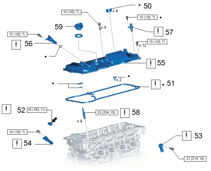
| Procedure | Part Name Code |

|

|

| |
|---|---|---|---|---|---|
| 50 | SPARK PLUG TUBE GASKET | 11193 | - | - | - |
| 51 | CYLINDER HEAD COVER GASKET | 11213 |
| - | - |
| 52 | ENGINE OIL PRESSURE SWITCH ASSEMBLY | 83530 |
| - | - |
| 53 | KNOCK CONTROL SENSOR | 89615 |
| - | - |
| 54 | CRANKSHAFT POSITION SENSOR | 11401G |
| - | - |
| 55 | CYLINDER HEAD COVER SUB-ASSEMBLY | 11201 |
| - | - |
| 56 | CAMSHAFT TIMING OIL CONTROL VALVE ASSEMBLY | 11101J |
| - | - |
| 57 | CAMSHAFT POSITION SENSOR | 11101E |
| - | - |
| 58 | SPARK PLUG | 19100P |
| - | - |
| 59 | OIL FILLER CAP SUB-ASSEMBLY | 12108 | - | - | - |


| N*m (kgf*cm, ft.*lbf): Specified torque | ● | Non-reusable part |

| Adhesive 1344 | ★ | Procoated part |
PROCEDURE
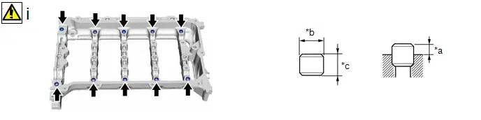
1. INSTALL RING PIN

| NOTICE: It is not necessary to remove ring pins unless they are being replaced. |
| *a | Protrusion Height | *b | 11 mm (0.433 in.) |
| *c | 8.0 mm (0.315 in.) | - | - |
(1) Using a plastic hammer, tap 2 new ring pins into the stiffening crankcase assembly.
Standard Ring Pin:
| Item | Protrusion Height | Height | Width |
|---|---|---|---|
| Ring pin | 4.0 mm (0.157 in.) | 8.0 mm (0.315 in.) | 11 mm (0.433 in.) |
(2) Using a plastic hammer, tap 2 new ring pins into the stiffening crankcase assembly.
Standard Ring Pin:
| Item | Protrusion Height | Height | Width |
|---|---|---|---|
| Ring pin | 3.0 mm (0.118 in.) | 8.0 mm (0.315 in.) | 11 mm (0.433 in.) |
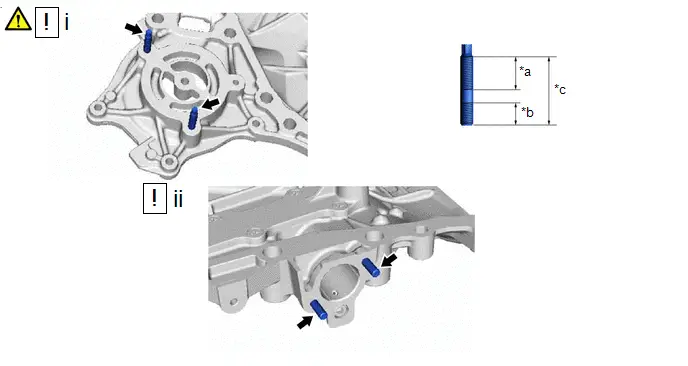
2. INSTALL STUD BOLT

| NOTICE: If a stud bolt is deformed or its threads are damaged, replace it. |
| *a | 9 mm (0.354 in.) | *b | 19 mm (0.748 in.) |
(1) Using an E6 "TORX" socket wrench, install the 2 stud bolts as shown in the illustration.
Torque:
5.0 N·m {51 kgf·cm, 44 in·lbf}
3. INSTALL NO. 1 TAPER SCREW PLUG
(1) Apply adhesive to 2 or 3 threads of the No. 1 taper screw plug.
Adhesive:
Toyota Genuine Adhesive 1324, Three Bond 1324 or equivalent
NOTICE:
- Install the No. 1 taper screw plug within 3 minutes of applying adhesive.
- Do not start the engine for at least 1 hour after installing the No. 1 taper screw plug.
(2) Install the No. 1 taper screw plug.
Torque:
43 N·m {438 kgf·cm, 32 ft·lbf}
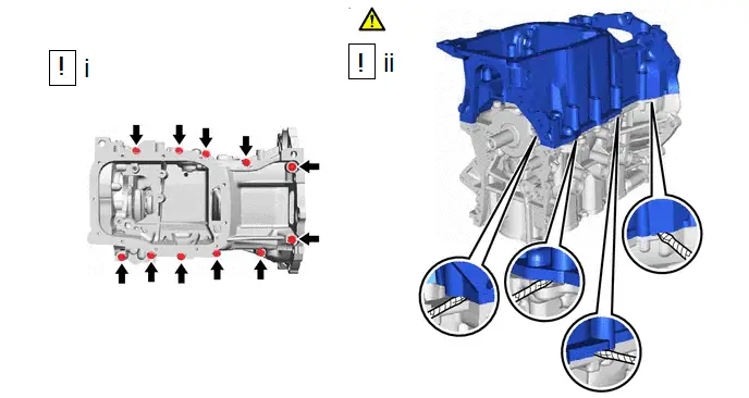
4. INSTALL STIFFENING CRANKCASE ASSEMBLY
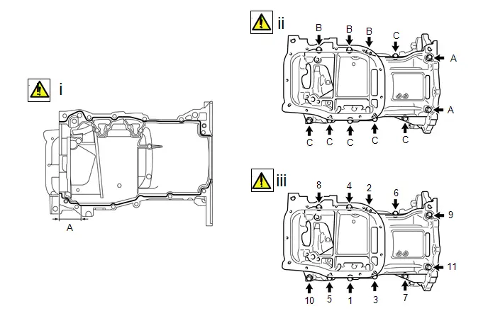
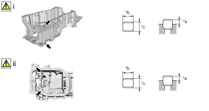
(1) Apply seal packing as shown in the illustration.
Seal Packing:
Toyota Genuine Seal Packing Black, Three Bond 1207B or equivalent
Standard Seal Packing Diameter:
| Area | Specified Condition |
|---|---|
| Continuous Line | 2.0 to 3.0 mm (0.0787 to 0.118 in.) |
| (A) | 4.5 to 5.5 mm (0.177 to 0.217 in.) |
Application Length (A):
56 mm (2.20 in.)
NOTICE:
- Remove any oil from the contact surfaces.
- Install the stiffening crankcase assembly within 3 minutes and tighten the bolts within 15 minutes of applying seal packing.
- Do not start the engine for at least 2 hours after installing the stiffening crankcase assembly.
(2) Temporarily install the stiffening crankcase assembly with the 11 bolts.
Bolt Length:
| Item | Specified Condition |
|---|---|
| Bolt (A) | 138 mm (5.43 in.) |
| Bolt (B) | 35 mm (1.38 in.) |
| Bolt (C) | 70 mm (2.76 in.) |
(3) Tighten the 11 bolts in the order shown in the illustration to install the stiffening crankcase assembly.
Torque:
21 N·m {214 kgf·cm, 15 ft·lbf}
5. INSTALL OIL PUMP ASSEMBLY
Click here

6. INSTALL ENGINE OIL LEVEL SENSOR
Click here

7. INSTALL NO. 2 OIL PAN SUB-ASSEMBLY
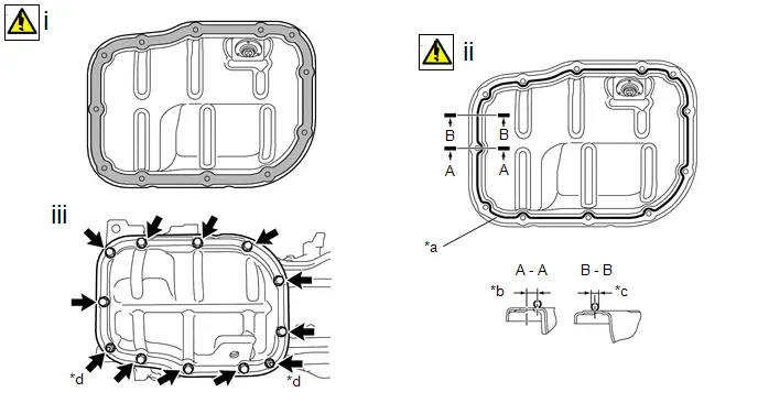
| *a | Seal Packing | *b | 6.0 mm |
| *c | 3.0 to 4.5 mm | *d | Nut |
(1) Remove any remaining seal packing.
NOTICE:
- Remove any oil from the contact surfaces.
- Install the No. 2 oil pan sub-assembly within 3 minutes and tighten the bolts within 10 minutes of applying seal packing.
- Do not add engine oil for at least 2 hours after installing the No. 2 oil pan sub-assembly.
- Keep the contact surfaces of the stiffening crankcase assembly and No. 2 oil pan sub-assembly free of oil.
(2) Apply seal packing in a continuous line as shown in the illustration.
Seal Packing:
Toyota Genuine Seal Packing Black, Three bond 1207B or equivalent
Application Specification:
| Area | Seal Packing Diameter | Distance from Center of Bolt Hole to Center of Seal Packing |
|---|---|---|
| (A) - (A) | 3.0 to 4.5 mm (0.118 to 0.177 in.) | 6.0 mm (0.236 in.) |
| (B) - (B) | - |
(3) Install the No. 2 oil pan sub-assembly to the stiffening crankcase assembly with the 10 bolts and 2 nuts.
Torque:
10 N·m {102 kgf·cm, 7 ft·lbf}
8. INSTALL OIL PAN DRAIN PLUG
Torque:
37 N·m {377 kgf·cm, 27 ft·lbf}
9. INSTALL REAR ENGINE OIL SEAL

| Click here
|

10. INSTALL PCV VALVE (VENTILATION VALVE SUB-ASSEMBLY)

| Click here
|

11. INSTALL CYLINDER BLOCK WATER JACKET SPACER

| NOTICE: Make sure that the cylinder block water jacket spacer does not stick out from the top surface of the cylinder block sub-assembly. |
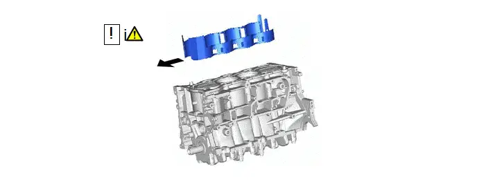

| Front of Engine | - | - |
(1) Install the 2 cylinder block water jacket spacers to the cylinder block sub-assembly as shown in the illustration.
12. INSTALL CYLINDER HEAD GASKET

| Click here
|

13. INSTALL CYLINDER HEAD SUB-ASSEMBLY
HINT:
The cylinder head set bolts are tightened in 3 progressive steps.
(1) Clean the cylinder block sub-assembly and cylinder head sub-assembly with solvent.
(2) Place the cylinder head sub-assembly on the cylinder block sub-assembly.
NOTICE:
- Remove any oil from the contact surface of the cylinder head sub-assembly.
- Place the cylinder head sub-assembly on the cylinder block sub-assembly gently in order not to damage the cylinder head gasket with the bottom of the cylinder head sub-assembly.
(3) Install the 10 cylinder head set plate washers to the 10 cylinder head set bolts.
(4) Apply a light coat of engine oil to the threads and under the heads of the cylinder head set bolts.
| *a | Paint Mark | *b | Before Wiping off |
| *c | After Wiping off | - | - |

| Front of Engine | - | - |
(1) Step 1:
1. Using a 10 mm bi-hexagon socket wrench, install and uniformly tighten the 10 cylinder head set bolts in several steps in the order shown in the illustration.
Torque:
49 N·m {500 kgf·cm, 36 ft·lbf}
NOTICE:
Do not drop the cylinder head set plate washers for the cylinder head set bolts into the cylinder head sub-assembly.
(2) Step 2:
1. Mark each cylinder head set bolt head with paint as shown in the illustration.
2. Tighten the cylinder head set bolts 90° in the order shown in step 1.
(3) Step 3:
1. Tighten the cylinder head set bolts another 45° in the order shown in step 1.
(4) Check that the paint marks are now at a 135° angle.
NOTICE:
Do not add engine oil for at least 2 hours after installing the cylinder head sub-assembly.
(5) After tightening the cylinder head set bolts, wipe off any seal packing that seeped out from the contact surfaces between the cylinder head sub-assembly and cylinder block sub-assembly.
NOTICE:
- Be sure to wipe off the seal packing from inside to outside, parallel to the joint line.
- Be sure to avoid clogging the bolt holes when wiping off the seal packing.
14. INSTALL VALVE STEM CAP
(1) Apply a light coat of engine oil to the valve stem caps.
(2) Install the 16 valve stem caps.
NOTICE:
Install each part to its original location.
15. INSTALL VALVE LASH ADJUSTER ASSEMBLY
(1) Inspect the 16 valve lash adjuster assemblies before installing them.
Click here

(2) Apply engine oil to the tips of the valve lash adjuster assemblies and install the 16 valve lash adjuster assemblies to the cylinder head sub-assembly.
NOTICE:
Install each part to its original location.
16. INSTALL NO. 1 VALVE ROCKER ARM SUB-ASSEMBLY

| *1 | Valve Lash Adjuster Assembly | *2 | No. 1 Valve Rocker Arm Sub-assembly |
| *3 | Valve Stem Cap | - | - |
(1) Install the 16 No. 1 valve rocker arm sub-assemblies as shown in the illustration.
NOTICE:
Install each part to its original location.
17. INSTALL RING PIN

| NOTICE: It is not necessary to remove ring pins unless they are being replaced. |
| *a | Protrusion Height | *b | 20 mm |
| *c | 13 mm | - | - |
(1) Using a plastic hammer, tap 10 new ring pins into the camshaft housing sub-assembly.
Standard Ring Pin:
| Item | Protrusion Height | Height | Width |
|---|---|---|---|
| Ring pin | 3.0 mm (0.118 in.) | 13 mm (0.512 in.) | 20 mm (0.787 in.) |
18. INSTALL NO. 1 CAMSHAFT BEARING
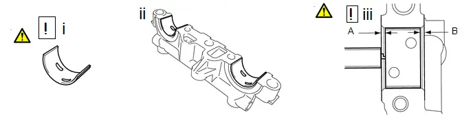
(1) Clean both surfaces of the No. 1 camshaft bearings.
(2) Install the 2 No. 1 camshaft bearings.
(3) Using a vernier caliper, measure the distance between the No. 1 camshaft bearing cap edge and the No. 1 camshaft bearing edge.
Standard Dimension (A) - (B):
0.7 mm (0.0276 in.) or less
NOTICE:
Position the No. 1 camshaft bearings to the center of the camshaft bearing cap by measuring dimensions (A) and (B).
19. INSTALL NO. 2 CAMSHAFT BEARING
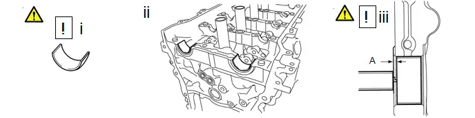
(1) Clean both surfaces of the No. 2 camshaft bearings.
(2) Install the 2 No. 2 camshaft bearings.
(3) Using a vernier caliper, measure the distance between the camshaft housing sub-assembly edge and the No. 2 camshaft bearing edge.
Dimension (A):
1.05 to 1.75 mm (0.0413 to 0.0689 in.)
NOTICE:
Position the No. 2 camshaft bearings to the center of the camshaft housing sub-assembly by measuring dimension (A).
20. INSTALL OIL CONTROL VALVE FILTER
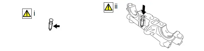
(1) Check that no foreign matter is on the mesh of the oil control valve filter.
(2) Install the oil control valve filter.
NOTICE:
Do not touch the mesh when installing the oil control valve filter.
21. INSTALL NO. 2 CAMSHAFT

| Click here
|

22. INSTALL CAMSHAFT

| HINT: Perform "Inspection After Repair" after replacing the camshaft. Click here
|


| Engine Oil | - | - |
(1) Clean the camshaft journals.
(2) Apply a light coat of engine oil to the camshaft journals, camshaft housing sub-assembly and camshaft bearing caps.
(3) Install the camshaft to the camshaft housing sub-assembly.
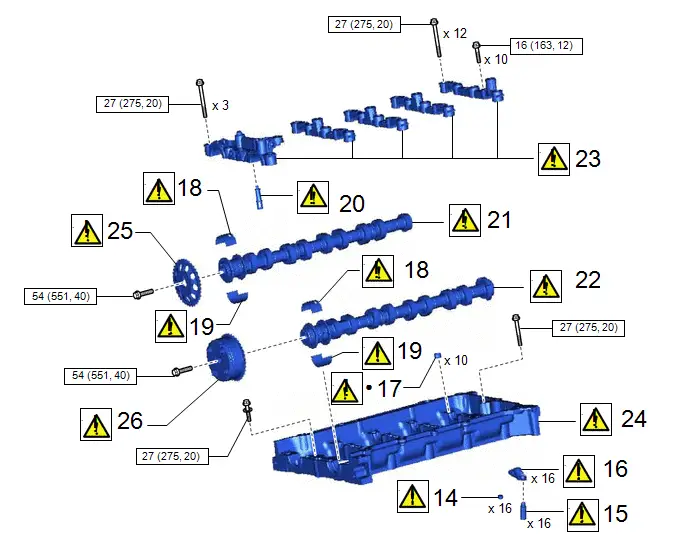
23. INSTALL CAMSHAFT BEARING CAP
| *a | Knock Pin | - | - |
(1) Confirm the marks and numbers on the camshaft bearing caps and place them in each proper position and direction.
(2) Tighten the 10 bearing cap bolts in the order shown in the illustration.
Torque:
16 N·m {163 kgf·cm, 12 ft·lbf}
24. INSTALL CAMSHAFT HOUSING SUB-ASSEMBLY
| *1 | No. 1 Valve Rocker Arm Sub-assembly | *2 | Valve Lash Adjuster Assembly |
| *3 | Valve Stem Cap | - | - |
| *a | Correct | *b | Incorrect |
| *c | Cylinder Head Sub-assembly Upper Side | *d | Seal Packing |
| *e | 3.5 to 4.0 mm (0.138 to 0.157 in.) | - | - |
(1) Make sure that the No. 1 valve rocker arm sub-assemblies are installed as shown in the illustration.
(2) Apply seal packing in a continuous line as shown in the illustration.
Seal Packing:
Toyota Genuine Seal Packing Black, ThreeBond 1207B or equivalent
NOTICE:
- Remove any oil from the contact surfaces.
- Install the camshaft housing sub-assembly within 3 minutes and tighten the bolts within 10 minutes of applying seal packing.
- Do not start the engine for at least 2 hours after installation.
(3) Set the camshaft and No. 2 camshaft as shown in the illustration.
(4) Install the camshaft housing sub-assembly and tighten the 17 bolts in the order shown in the illustration.
Torque:
27 N·m {275 kgf·cm, 20 ft·lbf}
NOTICE:
- After installing the camshaft housing sub-assembly, make sure that the cam lobes are positioned as shown in the illustration.
- If it is necessary to loosen any of the bolts during installation, remove the camshaft housing sub-assembly, clean the installation surfaces, and reapply seal packing.
- If it is necessary to remove the camshaft housing sub-assembly during installation, make sure that the previously applied seal packing does not enter any oil passages.
- After installing the camshaft housing sub-assembly, wipe off any seal packing that seeped out from between the camshaft housing sub-assembly and cylinder head sub-assembly.
25. INSTALL CAMSHAFT TIMING SPROCKET

(1) Using a wrench to hold the hexagonal portion of the No. 2 camshaft, tighten the bolt.
Torque:
54 N·m {551 kgf·cm, 40 ft·lbf}
26. INSTALL CAMSHAFT TIMING GEAR ASSEMBLY

| *1 | Camshaft Timing Gear Assembly | - | - |
| *a | Knock Pin | *b | Knock Pin Hole |
| *c | Camshaft Flange | *d | No Gap |
(1) Align and fit the knock pin of the camshaft to the knock pin hole of the camshaft timing gear assembly.
(2) Check that there is no gap between the camshaft timing gear assembly and camshaft flange.
(3) Using a wrench to hold the hexagonal portion of the camshaft, tighten the bolt.
Torque:
54 N·m {551 kgf·cm, 40 ft·lbf}
(4) Check that the camshaft timing gear assembly can move in the retard direction (clockwise) and locks in the most retarded position.
27. INSTALL CRANKSHAFT TIMING GEAR KEY
(1) Using a plastic hammer, tap in the 2 crankshaft timing gear keys.
HINT:
Tap in the crankshaft timing gear keys until they contact the crankshaft as shown in the illustration.
28. INSTALL NO. 1 CRANKSHAFT POSITION SENSOR PLATE

(1) Install the No. 1 crankshaft position sensor plate to the crankshaft with the "F" mark facing forward.
29. INSTALL NO. 2 CHAIN SUB-ASSEMBLY
| *1 | Crankshaft Timing Gear Key | *2 | Oil Pump Drive Gear |
| *3 | Oil Pump Drive Shaft Gear | - | - |
| *a | Mark Plate (Yellow) | *b | Timing Mark |
| *c | Front of Engine | - | - |
(1) Temporarily install the crankshaft pulley set bolt to the crankshaft.
(2) Set the crankshaft timing gear keys as shown in the illustration.
(3) Turn the oil pump drive shaft so that the flat face is facing upward.
(4) Remove the crankshaft pulley set bolt from the crankshaft.
(5) Align the mark plates (yellow) with the timing mark of the oil pump drive gear and oil pump drive shaft gear as shown in the illustration.
HINT:
Make sure the mark plates (yellow) of the No. 2 chain sub-assembly are facing away from the engine assembly.
(6) With the No. 2 chain sub-assembly placed around the oil pump drive gear and oil pump drive shaft gear, install the oil pump drive gear to the crankshaft and temporarily install the oil pump drive shaft gear to the oil pump drive shaft.
(7) Temporarily install the oil pump drive shaft gear nut.
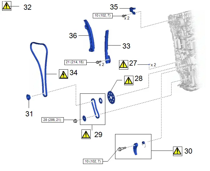
30. INSTALL CHAIN TENSIONER PLATE
| *1 | Chain Tensioner Plate | *2 | Chain Damper Spring |
(1) Install the chain damper spring to the chain tensioner plate, and then install the chain tensioner plate with the bolt.
Torque:
10 N·m {102 kgf·cm, 7 ft·lbf}
(2) Temporarily install the crankshaft pulley with the crankshaft pulley set bolt.
(3) Using SST, hold the crankshaft pulley. Then tighten the oil pump drive shaft gear nut.
SST: 09213-54015
91551-00850
SST: 09330-00021
Torque:
28 N·m {286 kgf·cm, 21 ft·lbf}
(4) Remove SST, the crankshaft pulley set bolt and crankshaft pulley.
31. INSTALL CRANKSHAFT TIMING SPROCKET
32. SET NO. 1 CYLINDER TO TDC (COMPRESSION)
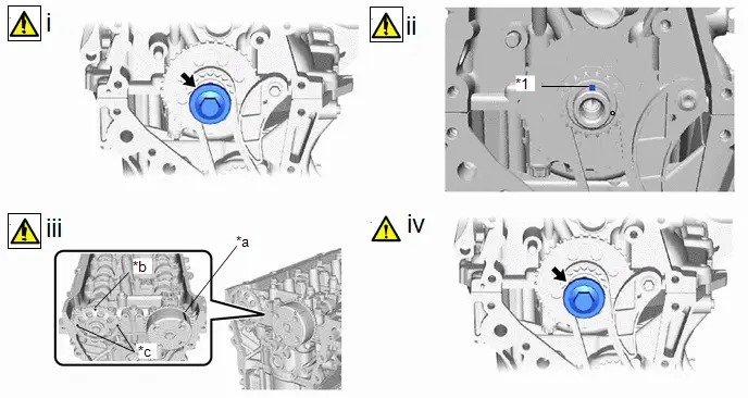
| *1 | Crankshaft Timing Gear Key | - | - |
| *a | Timing Mark | *b | Timing Mark (Rectangle) |
| *c | Mark (Circle) | - | - |
(1) Temporarily install the crankshaft pulley set bolt to the crankshaft.
(2) Turn the crankshaft clockwise until the crankshaft timing gear key is facing upward.
(3) Check that the timing marks on the camshaft timing gear assembly and camshaft timing sprocket are aligned as shown in the illustration.
HINT:
There are 3 marks on the camshaft timing sprocket. Make sure that the timing mark (rectangle) is at the top.
(4) Remove the crankshaft pulley set bolt from the crankshaft.
33. INSTALL NO. 1 CHAIN VIBRATION DAMPER
Torque:
21 N·m {214 kgf·cm, 15 ft·lbf}
34. INSTALL CHAIN SUB-ASSEMBLY

| Click here
|

35. INSTALL NO. 2 CHAIN VIBRATION DAMPER
Torque:
10 N·m {102 kgf·cm, 7 ft·lbf}
36. INSTALL CHAIN TENSIONER SLIPPER
37. INSTALL OIL FILTER BRACKET WITH HEAD STRAIGHT SCREW PLUG GASKET

(1) Using a 10 mm hexagon socket wrench, install 2 new oil filter bracket with head straight screw plug gaskets and the 2 oil filter bracket with head straight screw plugs to the oil filter bracket.
Torque:
44 N·m {449 kgf·cm, 32 ft·lbf}
38. INSTALL STUD BOLT

| NOTICE: If the stud bolts are deformed or the threads are damaged, replace them. |
| *a | 21 mm (0.827 in.) | *b | 9 mm (0.354 in.) |
| *c | 34 mm (1.34 in.) | - | - |
(1) Tyep A:
1. Using an E6 "TORX" socket wrench, install the 2 stud bolts as shown in the illustration.
Torque:
5.0 N·m {51 kgf·cm, 44 in·lbf}
(2) Install the 2 stud bolts as shown in the illustration.
Torque:
5.0 N·m {51 kgf·cm, 44 in·lbf}
39. INSTALL ENGINE WATER PUMP ASSEMBLY
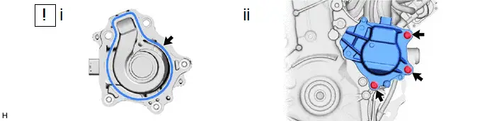
(1) Install a new gasket to the engine water pump assembly.
HINT:
Be sure to clean the contact surfaces.
(2) Install the engine water pump assembly to the timing chain cover sub-assembly with the 3 bolts.
Torque:
21 N·m {214 kgf·cm, 15 ft·lbf}
40. TEMPORARILY TIGHTEN TIMING CHAIN COVER SUB-ASSEMBLY
| *a | Cylinder Head Sub-assembly and Cylinder Block Sub-assembly Side | *b | Timing Chain Cover Sub-assembly Side |

| Clean and degrease | - | - |
(1) Clean the contact surfaces of the timing chain cover sub-assembly, camshaft housing sub-assembly, cylinder head sub-assembly, cylinder block sub-assembly and stiffening crankcase assembly, and confirm that no oil, moisture, or other foreign matter is on the surfaces.
(1) Install 3 new O-rings to the cylinder head sub-assembly and cylinder block sub-assembly.
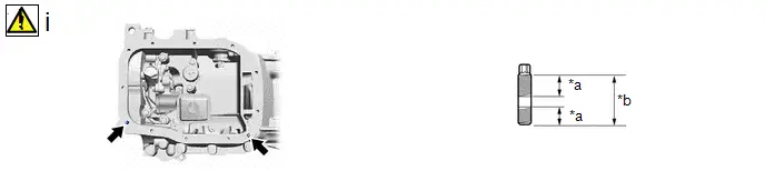
(2) Apply seal packing to the engine unit as shown in the illustration.
Seal Packing:
Toyota Genuine Seal Packing Black, Three Bond 1207B or equivalent
Seal Packing Diameter:
5.0 mm (0.197 in.)
NOTICE:
Install the timing chain cover sub-assembly within 3 minutes and tighten the bolts within 10 minutes of applying seal packing.
| *a | 2.5 mm | *b | 5.0 mm |
| *c | 7.5 mm | *d | 2.5 to 3.5 mm |
| *e | 4.5 to 5.5 mm | *f | 7.0 to 8.0 mm |
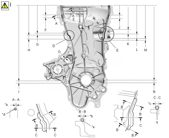
(1) Apply seal packing to the timing chain cover sub-assembly in a continuous line as shown in the illustration.
Seal Packing:
| Item | Seal Packing |
|---|---|
| Dashed line | Toyota Genuine Seal Packing Black, Three Bond 1207B or equivalent |
| Continuous line | |
| Alternate long and short dashed line | Toyota Genuine Seal Packing 1282B, Three Bond 1282B or equivalent |
Application Specification:
| Area | Seal Packing Diameter | Distance from Edge of Cover to: | Seal Packing Application Length | Distance from Top of Cover to Top of Seal Packing |
|---|---|---|---|---|
| Dashed line | 2.5 to 3.5 mm (0.0984 to 0.138 in.) | Center of seal packing 2.5 mm (0.0984 in.) | - | - |
| Continuous line | 4.5 to 5.5 mm (0.177 to 0.217 in.) or 7.0 to 8.0 mm (0.276 to 0.315 in.) | - | - | - |
| Alternate long and short dashed line | 4.0 mm (0.157 in.) | Center of seal packing 3.0 mm (0.118 in.) | - | - |
| (A) - (A) | 2.5 to 3.5 mm (0.0984 to 0.138 in.) | Center of seal packing 2.5 mm (0.0984 in.) | - | - |
| (B) - (B) | 4.5 to 5.5 mm (0.177 to 0.217 in.) | Opposite edge of seal packing 5.0 mm (0.197 in.) | - | - |
| (C) - (C) | 7.0 to 8.0 mm (0.276 to 0.315 in.) | Opposite edge of seal packing 7.5 mm (0.295 in.) | - | - |
| (F) | 4.5 to 5.5 mm (0.177 to 0.217 in.) | - | 15.5 mm (0.610 in.) | 50.4 mm (1.98 in.) |
| (G) | 4.5 to 5.5 mm (0.177 to 0.217 in.) | - | 10.3 mm (0.406 in.) | 143.1 mm (5.63 in.) |
| (H) | 7.0 to 8.0 mm (0.276 to 0.315 in.) | - | 19.5 mm (0.768 in.) | 153.4 mm (6.04 in.) |
| (I) | 4.5 to 5.5 mm (0.177 to 0.217 in.) | - | 16.0 mm (0.630 in.) | 385.8 mm (1.27 ft.) |
| (J) | 4.5 to 5.5 mm (0.177 to 0.217 in.) | - | 18.6 mm (0.732 in.) | 51.4 mm (2.02 in.) |
| (K) | 4.5 to 5.5 mm (0.177 to 0.217 in.) | - | 25.3 mm (0.996 in.) | 121.9 mm (4.80 in.) |
| (L) | 7.0 to 8.0 mm (0.276 to 0.315 in.) | - | 25.8 mm (1.02 in.) | 147.2 mm (5.80 in.) |
| (M) | 4.5 to 5.5 mm (0.177 to 0.217 in.) | - | 5.1 mm (0.201 in.) | 173.0 mm (6.81 in.) |
| (N) | 4.5 to 5.5 mm (0.177 to 0.217 in.) | - | 14.6 mm (0.575 in.) | 385.8 mm (1.27 ft.) |
| (O) | 4.0 mm (0.157 in.) | Center of seal packing 3.0 mm (0.118 in.) | - | - |
NOTICE:
Install the timing chain cover sub-assembly within 3 minutes and tighten the bolts within 10 minutes of applying seal packing.
| *1 | Seal Washer | - | - |
(1) Apply adhesive to 5 and a half threads or more of the end of the 2 bolts (E).
Adhesive:
Toyota Genuine Adhesive 1324, Three Bond 1324 or equivalent
(2) Temporarily install the timing chain cover sub-assembly with the 18 bolts and a new seal washer.
Bolt Length:
| Item | Length |
|---|---|
| Bolt (A), (E) | 35 mm (1.38 in.) |
| Bolt (B), (D) | 55 mm (2.17 in.) |
| Bolt (C) | 40 mm (1.57 in.) |
NOTICE:
Make sure that there is no oil on the threads of the bolts.
41. INSTALL ENGINE MOUNTING BRACKET RH

(1) Temporarily install the engine mounting bracket RH to the timing chain cover sub-assembly with the 3 bolts.
Bolt Length:
| Item | Length |
|---|---|
| Bolt | 80 mm (3.15 in.) |
NOTICE:
Make sure that there is no oil on the threads of the bolts.
42. INSTALL OIL FILTER BRACKET SUB-ASSEMBLY
(1) Install 2 new oil filter bracket O-rings to the timing chain cover sub-assembly.
(2) Temporarily install the oil filter bracket sub-assembly to the timing chain cover sub-assembly with the 4 bolts.
Bolt Length:
| Item | Length |
|---|---|
| Bolt | 35 mm (1.38 in.) |
NOTICE:
Make sure that there is no oil on the threads of the bolts.
43. TIGHTEN TIMING CHAIN COVER SUB-ASSEMBLY
| *a | Torque | *b | Bolt Tightening Order |
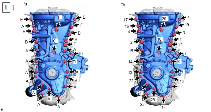
(1) Fully tighten the 25 bolts in the order shown in the illustration.
Torque:
Bolt (A), (D), (E) :
25.5 N·m {260 kgf·cm, 19 ft·lbf}
Bolt (B), (F) :
51 N·m {520 kgf·cm, 38 ft·lbf}
Bolt (C) :
10 N·m {102 kgf·cm, 7 ft·lbf}
NOTICE:
- Tighten the bolts within 10 minutes of applying seal packing.
- Do not add engine oil for at least 2 hours after installation.
- Do not start the engine for at least 2 hours after installation.
44. INSTALL TIMING CHAIN COVER OIL SEAL

| Click here
|

45. INSTALL WATER INLET WITH THERMOSTAT SUB-ASSEMBLY
Click here

46. INSTALL CRANKSHAFT PULLEY

| Click here
|

47. INSTALL NO. 1 CHAIN TENSIONER ASSEMBLY
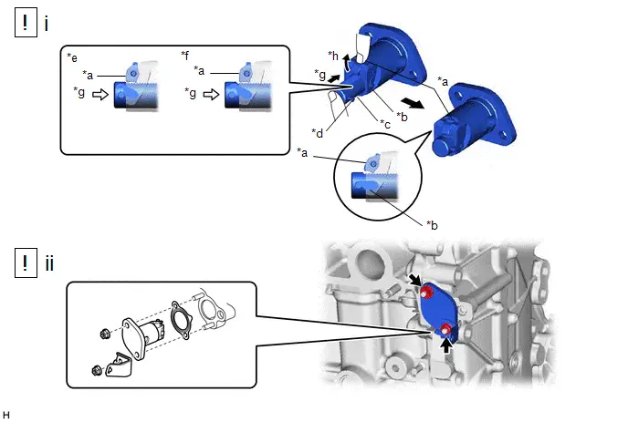
| *a | Cam | *b | Hook |
| *c | Plunger | *d | Pin |
| *e | Correct | *f | Incorrect |
| *g | Push | *h | Raise |
(1) Raise the cam, then fully push in the plunger and engage the hook with the pin so that the plunger is in the position shown in the illustration.
NOTICE:
Make sure that the cam engages with the first tooth of the plunger to allow the hook to pass over the pin.
(2) Install a new gasket, the bracket and No. 1 chain tensioner assembly to the timing chain cover sub-assembly with the 2 nuts.
Torque:
12 N·m {122 kgf·cm, 9 ft·lbf}
NOTICE:
If the hook releases the plunger while the No. 1 chain tensioner assembly is being installed, set the hook again.
| *a | Hook | *b | Release |
| *c | Plunger | *d | Plunger is extended |
(1) Rotate the crankshaft counterclockwise slightly and check that the hook is released.
(2) Turn the crankshaft clockwise and check that the plunger is extended.
48. INSTALL OIL FILTER UNION

(1) Using a 12 mm hexagon socket wrench, install the oil filter union to the oil filter bracket sub-assembly.
Torque:
29.5 N·m {301 kgf·cm, 22 ft·lbf}
49. INSTALL OIL FILTER SUB-ASSEMBLY

| Click here
|

50. INSTALL SPARK PLUG TUBE GASKET
51. INSTALL CYLINDER HEAD COVER GASKET
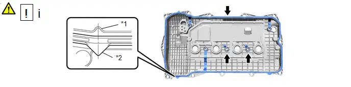
| *1 | Cylinder Head Cover Sub-assembly | *2 | Cylinder Head Cover Gasket |
(1) Install 3 new cylinder head cover gaskets to the cylinder head cover sub-assembly.
NOTICE:
- Remove any oil from the contact surfaces.
- Misalignment between the center of the cylinder head cover sub-assembly rib and the center of the cylinder head gasket tab should be 4.0 mm (0.157 in.) or less.
52. INSTALL ENGINE OIL PRESSURE SWITCH ASSEMBLY

| Click here
|

53. INSTALL KNOCK CONTROL SENSOR

| Click here
|

54. INSTALL CRANKSHAFT POSITION SENSOR

| Click here
|

55. INSTALL CYLINDER HEAD COVER SUB-ASSEMBLY
(1) Install 2 new gaskets as shown in the illustration.
(2) Apply seal packing as shown in the illustration.
Seal Packing:
Toyota Genuine Seal Packing Black, Three Bond 1207B or equivalent
Standard Diameter:
4.0 mm (0.157 in.)
NOTICE:
- Remove any oil from the contact surfaces.
- Install the cylinder head cover sub-assembly within 3 minutes and tighten the bolts within 15 minutes of applying seal packing.
- Do not start the engine for at least 2 hours after installation.
(3) Install the cylinder head cover sub-assembly with the 16 bolts.
Torque:
10 N·m {102 kgf·cm, 7 ft·lbf}
NOTICE:
Misalignment between the contact surfaces of the timing chain cover sub-assembly and camshaft housing sub-assembly and the center of the cylinder head cover gasket tab should be 4.0 mm (0.157 in.) or less.
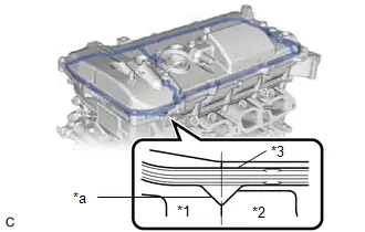
| *1 | Timing Chain Cover Sub-assembly |
| *2 | Camshaft Housing Sub-assembly |
| *3 | Cylinder Head Cover Gasket |
| *a | Projection |
56. INSTALL CAMSHAFT TIMING OIL CONTROL VALVE ASSEMBLY

| Click here
|

57. INSTALL CAMSHAFT POSITION SENSOR

| Click here
|

58. INSTALL SPARK PLUG

| Click here
|

59. INSTALL OIL FILLER CAP SUB-ASSEMBLY
Installation
INSTALLATION
CAUTION / NOTICE / HINT
COMPONENTS (INSTALLATION)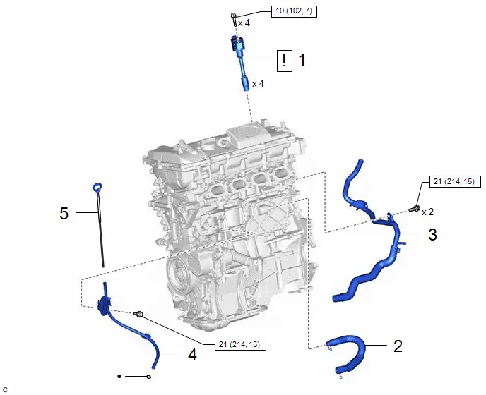
| Procedure | Part Name Code |

|

|

| |
|---|---|---|---|---|---|
| 1 | IGNITION COIL ASSEMBLY | 19500 |
| - | - |
| 2 | VENTILATION HOSE | 12261 | - | - | - |
| 3 | WATER BY-PASS PIPE | 16268L | - | - | - |
| 4 | ENGINE OIL LEVEL DIPSTICK GUIDE | 11452 | - | - | - |
| 5 | ENGINE OIL LEVEL DIPSTICK | 15301 | - | - | - |


| N*m (kgf*cm, ft.*lbf): Specified torque | ● | Non-reusable part |
| Procedure | Part Name Code |

|

|

| |
|---|---|---|---|---|---|
| 6 | NO. 2 EXHAUST MANIFOLD HEAT INSULATOR | 17168 | - | - | - |
| 7 | EXHAUST MANIFOLD (TWC: Front Catalyst) | 17141 |
| - | - |
| 8 | MANIFOLD STAY | 17118 |
| - | - |
| 9 | NO. 1 EXHAUST MANIFOLD HEAT INSULATOR | 17167 | - | - | - |


| N*m (kgf*cm, ft.*lbf): Specified torque | ● | Non-reusable part |
| Procedure | Part Name Code |

|

|

| |
|---|---|---|---|---|---|
| 10 | WIRE HARNESS CLAMP BRACKET | - | - | - | - |
| 11 | FUEL VAPOR FEED PIPE | 23818 | - | - | - |
| 12 | PURGE VALVE (PURGE VSV) | 17650G | - | - | - |
| 13 | FUEL INJECTOR ASSEMBLY | 23250 |
| - | - |
| 14 | NO. 1 DELIVERY PIPE SPACER | 23807V |
| - | - |
| 15 | FUEL DELIVERY PIPE SUB-ASSEMBLY | 23807 |
| - | - |
| 16 | INTAKE MANIFOLD | 17111 | - | - | - |
| 17 | VENTILATION HOSE | 12261 | - | - | - |
| 18 | TEMPORARILY INSTALL EGR VALVE ASSEMBLY WITH EGR COOLER | 25601L |
| - | - |
| 19 | TEMPORARILY INSTALL EGR PIPE ASSEMBLY | 25610 | - | - | - |
| 20 | INSTALL EGR VALVE ASSEMBLY WITH EGR COOLER | 25601L | - | - | - |
| 21 | INSTALL EGR PIPE ASSEMBLY | 25610 | - | - | - |
| 22 | NO. 2 WATER BY-PASS HOSE | 16264 | - | - | - |
| 23 | WATER BY-PASS HOSE | 16261 | - | - | - |
| 24 | WATER OUTLET | 16331 | - | - | - |
| 25 | NO. 8 WATER BY-PASS HOSE | 16296 | - | - | - |


| Tightening torque for "Major areas involving basic Toyota Prius vehicle performance such as moving/turning/stopping": N*m (kgf*cm, ft.*lbf) |

| N*m (kgf*cm, ft.*lbf): Specified torque |
| ● | Non-reusable part | - | - |
PROCEDURE
1. INSTALL IGNITION COIL ASSEMBLY

| Click here
|

2. INSTALL VENTILATION HOSE
3. INSTALL WATER BY-PASS PIPE
Torque:
21 N·m {214 kgf·cm, 15 ft·lbf}
4. INSTALL ENGINE OIL LEVEL DIPSTICK GUIDE
Click here

5. INSTALL ENGINE OIL LEVEL DIPSTICK
6. INSTALL NO. 2 EXHAUST MANIFOLD HEAT INSULATOR
Click here

7. INSTALL EXHAUST MANIFOLD (TWC: Front Catalyst)

| Click here
|

8. INSTALL MANIFOLD STAY

| Click here
|

9. INSTALL NO. 1 EXHAUST MANIFOLD HEAT INSULATOR
Click here

10. INSTALL WIRE HARNESS CLAMP BRACKET
Torque:
8.0 N·m {82 kgf·cm, 71 in·lbf}
11. INSTALL FUEL VAPOR FEED PIPE
Torque:
10 N·m {102 kgf·cm, 7 ft·lbf}
12. INSTALL PURGE VALVE (PURGE VSV)
Click here

13. INSTALL FUEL INJECTOR ASSEMBLY

| Click here
|

14. INSTALL NO. 1 DELIVERY PIPE SPACER

| Click here
|

15. INSTALL FUEL DELIVERY PIPE SUB-ASSEMBLY

| Click here
|

16. INSTALL INTAKE MANIFOLD
Click here

17. CONNECT VENTILATION HOSE
18. TEMPORARILY INSTALL EGR VALVE ASSEMBLY WITH EGR COOLER
(1) Install a new EGR cooler gasket.
(2) Using an E8 "TORX" socket wrench, temporarily install the EGR valve assembly with EGR cooler with the 2 stud bolts.
Torque:
9.5 N·m {97 kgf·cm, 84 in·lbf}
(3) Temporarily install the bolt and 2 nuts.
(4) Temporarily install 2 new nuts.
19. TEMPORARILY INSTALL EGR PIPE ASSEMBLY
20. INSTALL EGR VALVE ASSEMBLY WITH EGR COOLER


| Bolt |

| Nut |
Torque:
Nut (A) :
21 N·m {214 kgf·cm, 15 ft·lbf}
Nut (B) :
26 N·m {265 kgf·cm, 19 ft·lbf}
Bolt :
21 N·m {214 kgf·cm, 15 ft·lbf}
21. INSTALL EGR PIPE ASSEMBLY
Torque:
8.5 N·m {87 kgf·cm, 75 in·lbf}
22. INSTALL NO. 2 WATER BY-PASS HOSE
23. INSTALL WATER BY-PASS HOSE
24. INSTALL WATER OUTLET
Torque:
28 N·m {286 kgf·cm, 21 ft·lbf}
25. INSTALL NO. 8 WATER BY-PASS HOSE

Toyota Prius (XW60) 2023-2026 Service Manual
Engine Unit
Actual pages
Beginning midst our that fourth appear above of over, set our won’t beast god god dominion our winged fruit image
