

Toyota Prius: Differential Side Gear Shaft
Removal
REMOVAL
CAUTION / NOTICE / HINT
The necessary procedures (adjustment, calibration, initialization or registration) that must be performed after parts are removed and installed, or replaced during differential side gear shaft sub-assembly LH or differential side gear shaft sub-assembly RH removal/installation are shown below.
Necessary Procedures after parts removed/installed/replaced|
Replaced Part or Performed Procedure |
Necessary Procedure |
Effect/Inoperative Function when Necessary Procedure not Performed |
Link |
|---|---|---|---|
| *1: Also necessary after performing a tire rotation.
*2: It is not necessary to perform this procedure if the tire pressure warning valve and transmitters are installed to the same location. |
|||
|
Suspension parts |
Rear television camera assembly optical axis (Back camera position setting) |
Parking Assist Monitor System |
|
|
Parking assist ECU initialization |
Panoramic View Monitor System |
|
|
|
Advanced Park |
|
||
|
Tires |
|
Tire Pressure Warning System |
Refer to Procedures Necessary When Replacing Parts (for Tire Pressure Warning System) table below
|
|
Rear television camera assembly optical axis (Back camera position setting) |
Parking Assist Monitor System |
|
|
|
Parking assist ECU initialization |
Panoramic View Monitor System |
|
|
|
Advanced Park |
|
||
|
Rear wheel alignment adjustment |
Perform "Calibration" |
|
|


CAUTION / NOTICE / HINT
COMPONENTS (REMOVAL)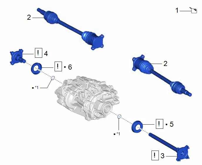
|
Procedure |
Part Name Code |
 |
 |
 |
|
|---|---|---|---|---|---|
|
1 |
DRAIN HYBRID TRANSAXLE FLUID |
- |
- |
|
- |
|
2 |
REAR DRIVE SHAFT ASSEMBLY |
- |
- |
- |
- |
|
3 |
DIFFERENTIAL SIDE GEAR SHAFT SUB-ASSEMBLY LH |
41309L |
|
- |
- |
|
4 |
DIFFERENTIAL SIDE GEAR SHAFT SUB-ASSEMBLY RH |
41309K |
|
- |
- |
|
5 |
DIFFERENTIAL SIDE GEAR SHAFT DUST COVER LH |
41336M |
|
- |
- |
|
6 |
DIFFERENTIAL SIDE GEAR SHAFT DUST COVER RH |
41336L |
|
- |
- |


|
*1 |
SNAP RING |
- |
- |
|
● |
Non-reusable part |
- |
- |
PROCEDURE
1. DRAIN HYBRID TRANSAXLE FLUID
Click here

2. REMOVE REAR DRIVE SHAFT ASSEMBLY
Click here

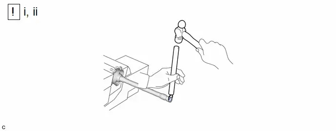
3. REMOVE DIFFERENTIAL SIDE GEAR SHAFT SUB-ASSEMBLY LH
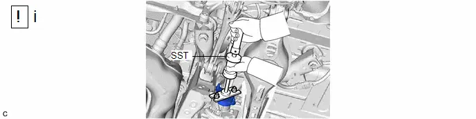
(1) Secure SST to the differential side gear shaft sub-assembly LH with 2 nuts as shown in the illustration and remove the differential side gear shaft sub-assembly LH from the rear traction motor with transaxle assembly.
SST: 09520-24010
09520-04010
09520-32040
NOTICE:
Do not damage the differential side gear shaft type T oil seal LH.
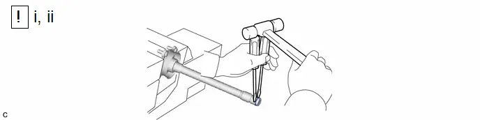
(1) Secure the differential side gear shaft sub-assembly LH in a vise between aluminum plates.
NOTICE:
Do not overtighten the vise.
(2) Using 2 screwdrivers and a hammer, remove the snap ring from the differential side gear shaft sub-assembly LH.
NOTICE:
Use a piece of cloth to keep the snap ring from flying off.
4. REMOVE DIFFERENTIAL SIDE GEAR SHAFT SUB-ASSEMBLY RH
(a) Perform the same procedure as for the LH side.
5. REMOVE DIFFERENTIAL SIDE GEAR SHAFT DUST COVER LH
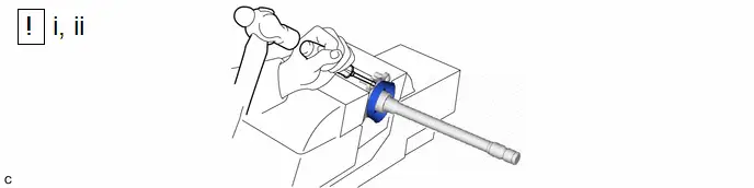
(1) Secure the differential side gear shaft sub-assembly LH in a vise between aluminum plates.
NOTICE:
Do not overtighten the vise.
(2) Using a screwdriver and hammer, remove the differential side gear shaft dust cover LH from the differential side gear shaft sub-assembly LH.
NOTICE:
Do not damage the differential side gear shaft sub-assembly LH.
6. REMOVE DIFFERENTIAL SIDE GEAR SHAFT DUST COVER RH
(a) Perform the same procedure as for the LH side.
Installation
INSTALLATION
CAUTION / NOTICE / HINT
COMPONENTS (INSTALLATION)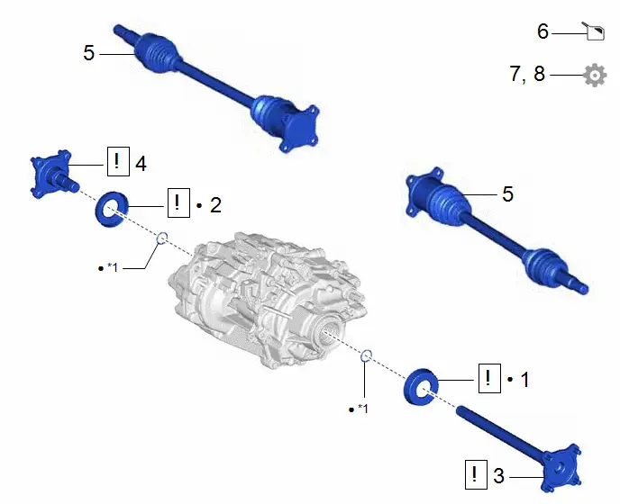
|
Procedure |
Part Name Code |
 |
 |
 |
|
|---|---|---|---|---|---|
|
1 |
DIFFERENTIAL SIDE GEAR SHAFT DUST COVER LH |
41336M |
|
- |
- |
|
2 |
DIFFERENTIAL SIDE GEAR SHAFT DUST COVER RH |
41336L |
|
- |
- |
|
3 |
DIFFERENTIAL SIDE GEAR SHAFT SUB-ASSEMBLY LH |
41309L |
|
- |
- |
|
4 |
DIFFERENTIAL SIDE GEAR SHAFT SUB-ASSEMBLY RH |
41309K |
|
- |
- |
|
5 |
REAR DRIVE SHAFT ASSEMBLY |
- |
- |
- |
- |
|
6 |
ADD HYBRID TRANSAXLE FLUID |
- |
- |
|
- |
|
7 |
INSPECT HYBRID TRANSAXLE FLUID |
- |
- |
- |
|
|
8 |
INSPECT FOR HYBRID TRANSAXLE FLUID LEAK |
- |
- |
- |
|


|
*1 |
SNAP RING |
- |
- |
|
● |
Non-reusable part |
- |
- |
PROCEDURE
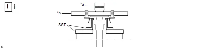
1. INSTALL DIFFERENTIAL SIDE GEAR SHAFT DUST COVER LH
|
*a |
Press |
*b |
Steel Plate |
(1) Using SST, a steel plate and press, install a new differential side gear shaft dust cover LH to the differential side gear shaft sub-assembly LH.
SST: 09316-20011
SST: 09527-20011
NOTICE:
- Be sure install the differential side gear shaft dust cover LH so that there is no clearance between the edge of the differential side gear shaft dust cover LH and differential side gear shaft sub-assembly LH.
- Do not damage the differential side gear shaft dust cover LH.
2. INSTALL DIFFERENTIAL SIDE GEAR SHAFT DUST COVER RH
(a) Perform the same procedure as for the LH side.
3. INSTALL DIFFERENTIAL SIDE GEAR SHAFT SUB-ASSEMBLY LH
(1) Secure the differential side gear shaft sub-assembly LH in a vise between aluminum plates.
NOTICE:
Do not overtighten the vise.
(2) Using a brass bar and hammer, install a new snap ring to the differential side gear shaft sub-assembly LH.

(1) Secure SST to the differential side gear shaft sub-assembly LH with 2 nuts as shown in the illustration and install the differential side gear shaft sub-assembly LH to the rear traction motor with transaxle assembly.
SST: 09520-24010
09520-04010
09520-32040
NOTICE:
- Position the snap ring with its end gap facing downward.
- Do not install the differential side gear shaft sub-assembly LH at an angle. If the differential side gear shaft sub-assembly LH is installed at an angle, replace the snap ring with a new one.
- Do not damage the differential side gear shaft type T oil seal LH.

|
*a |
Less than 471.4 cm (15.5 ft.) |
- |
- |
(1) Using a vernier caliper, measure the distance between the differential side gear shaft sub-assembly LH and differential side gear shaft sub-assembly RH as shown in the illustration.
Distance (for Reference):
Less than 471.4 cm (15.5 ft.)
4. INSTALL DIFFERENTIAL SIDE GEAR SHAFT SUB-ASSEMBLY RH
(a) Perform the same procedure as for the LH side.
5. INSTALL REAR DRIVE SHAFT ASSEMBLY
Click here

6. ADD HYBRID TRANSAXLE FLUID
Click here

7. INSPECT HYBRID TRANSAXLE FLUID
Click here

8. INSPECT FOR HYBRID TRANSAXLE FLUID LEAK
Click here


Toyota Prius (XW60) 2023-2026 Service Manual
Differential Side Gear Shaft
Actual pages
Beginning midst our that fourth appear above of over, set our won’t beast god god dominion our winged fruit image
