

Toyota Prius: Camshaft Oil Control Valve
On-vehicle Inspection
ON-VEHICLE INSPECTION
PROCEDURE
1. INSPECT CAMSHAFT TIMING OIL CONTROL VALVE ASSEMBLY
Pre-procedure1
(a) Put the engine in Inspection Mode (Maintenance Mode).
Powertrain > Hybrid Control > Utility| Tester Display |
|---|
| Inspection Mode |
(b) Start the engine.
Procedure1
(c) Check the engine speed while operating the camshaft timing oil control valve assembly using the GTS.
Powertrain > Engine > Active Test| Tester Display |
|---|
| Control the Intake VVT OCV Duty Ratio Bank 1 |
Standard Condition:
| GTS Operation | Specified Condition |
|---|---|
| 0% | Normal engine speed |
| 100% | Engine idles roughly or stalls |
HINT:
- Test not possible with park (P) selected during charge control. Select neutral (N) to perform test.
- If DTCs are stored after the Active Test, clear the DTCs.
If the operation is not as specified, check the camshaft timing oil control valve assembly, wire harness and ECM.
Post-procedure1
(d) None
Removal
REMOVAL
CAUTION / NOTICE / HINT
COMPONENTS (REMOVAL)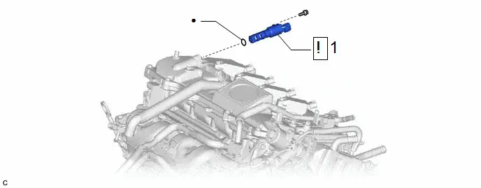
| Procedure | Part Name Code |

|

|

| |
|---|---|---|---|---|---|
| 1 | CAMSHAFT TIMING OIL CONTROL VALVE ASSEMBLY | 11101J |
| - | - |

| ● | Non-reusable part | - | - |
PROCEDURE
1. REMOVE CAMSHAFT TIMING OIL CONTROL VALVE ASSEMBLY
(1) Disconnect the camshaft timing oil control valve assembly connector.
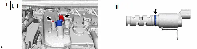
(2) Remove the bolt and camshaft timing oil control valve assembly from the cylinder head cover sub-assembly.
NOTICE:
- Do not allow foreign matter to contact the oil seal surface of the camshaft timing oil control valve assembly (connecting surface with the cylinder head cover sub-assembly).
- If the camshaft timing oil control valve assembly has been struck or dropped, replace it.
(3) Remove the O-ring from the camshaft timing oil control valve assembly.
Inspection
INSPECTION
PROCEDURE
1. INSPECT CAMSHAFT TIMING OIL CONTROL VALVE ASSEMBLY
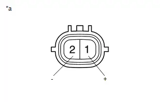
| (a) Measure the resistance according to the value(s) in the table below. Standard Resistance:
If the result is not as specified, replace the camshaft timing oil control valve assembly. |
|
(b) Check the operation.
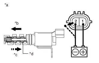
| (1) Connect a positive ( ) lead from the auxiliary battery to terminal 1 and a negative (-) lead to terminal 2, and check the movement of the spool valve. OK:
NOTICE: Confirm that the spool valve moves freely and does not stick in any position. If the result is not as specified, replace the camshaft timing oil control valve assembly. HINT: Accumulation of foreign matter can cause minor pressure leaks. Minor pressure leaks will cause the camshaft to advance or retard, and this will cause a DTC to be stored. |
|
Installation
INSTALLATION
CAUTION / NOTICE / HINT
COMPONENTS (INSTALLATION)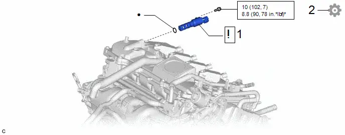
| Procedure | Part Name Code |

|

|

| |
|---|---|---|---|---|---|
| 1 | CAMSHAFT TIMING OIL CONTROL VALVE ASSEMBLY | 11101J |
| - | - |
| 2 | INSPECT FOR ENGINE OIL LEAK | - | - | - |
|


| N*m (kgf*cm, ft.*lbf): Specified torque | * | For use with a union nut wrench |
| ● | Non-reusable part | - | - |
PROCEDURE
1. INSTALL CAMSHAFT TIMING OIL CONTROL VALVE ASSEMBLY
| *a | 10 mm Union Nut Wrench | *b | Torque Wrench Fulcrum Length |
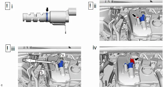
(1) Apply a light coat of engine oil to a new O-ring and install it to the camshaft timing oil control valve assembly.
NOTICE:
Do not damage the O-ring.
(2) Temporarily install the camshaft timing oil control valve assembly to the cylinder head cover sub-assembly with the bolt.
NOTICE:
- If the camshaft timing oil control valve assembly has been struck or dropped, replace it.
- Do not allow foreign matter to contact the oil seal face of the camshaft timing oil control valve assembly (connecting surface with the cylinder head cover sub-assembly).
- Make sure that the O-ring is not cracked or moved out of place when installing the camshaft timing oil control valve assembly.
(3) Using a 10 mm union nut wrench, tighten the bolt.
Torque:
Specified tightening torque :
10 N·m {102 kgf·cm, 7 ft·lbf}
HINT:
-
Calculate the torque wrench reading when changing the fulcrum length of the torque wrench.
Click here


-
When using a 10 mm union nut wrench (fulcrum length of 22 mm (0.866 in.)) torque wrench (fulcrum length of 162 mm (6.38 in.)):
8.8 N*m (90 kgf*cm, 78 in.*lbf)
(4) Connect the camshaft timing oil control valve assembly connector.
2. INSPECT FOR ENGINE OIL LEAK
Click here


Toyota Prius (XW60) 2023-2026 Service Manual
Camshaft Oil Control Valve
Actual pages
Beginning midst our that fourth appear above of over, set our won’t beast god god dominion our winged fruit image
