

Toyota Prius: Brake Pedal
Adjustment
ADJUSTMENT
PROCEDURE
1. INSPECT AND ADJUST BRAKE PEDAL HEIGHT
(a) Check the brake pedal height.
(1) Measure the shortest distance between the brake pedal pad surface and accelerator pedal pad as shown in the illustration.
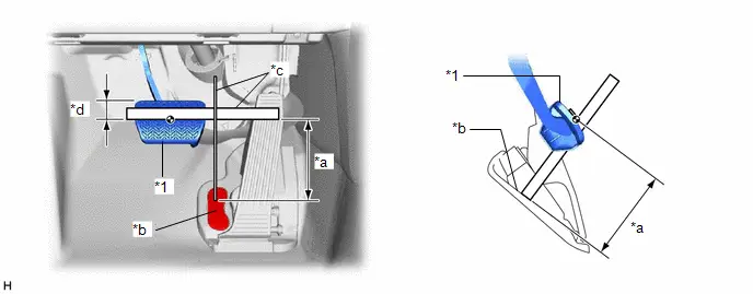
| *1 | Brake Pedal Pad | - | - |
| *a | Brake Pedal Height | *b | Measuring Plane of Accelerator Pedal Pad |
| *c | Ruler | *d | 35 mm (1.38 in.) |
Brake Pedal Height from Accelerator Pedal Pad:
125.3 to 141.3 mm (4.93 to 5.56 in.)
HINT:
If the brake pedal height is not as specified, inspect and adjust the push rod length according to the procedure below.
(b) Adjust the push rod length.
| (1) Remove the stop light switch assembly. Click here
|
|

(2) Loosen the master cylinder push rod nut.
(3) Adjust the brake pedal height by turning the push rod.
Brake Pedal Height from Accelerator Pedal Pad:
125.3 to 141.3 mm (4.93 to 5.56 in.)
(4) Tighten the master cylinder push rod nut.
Torque:
25.5 N·m {260 kgf·cm, 19 ft·lbf}
(5) Install the stop light switch assembly.
Click here

2. INSPECT AND ADJUST BRAKE PEDAL STROKE SENSOR
NOTICE:
Do not depress the brake pedal after turning the ignition switch to ON.
(a) Inspect the brake pedal stroke sensor.
(1) Read the stroke sensor value without the brake pedal depressed.
Chassis > Brake Booster > Data List| Tester Display |
|---|
| Stroke Sensor |
Standard Voltage (without the brake pedal depressed):
0.8 to 1.2 V
HINT:
If the stroke sensor value is not within the standard voltage, adjust the brake pedal stroke sensor.
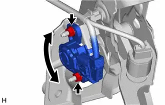
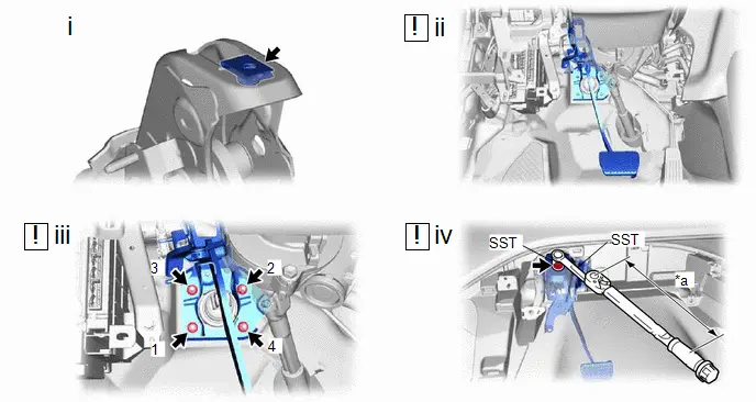
| (b) Adjust the brake pedal stroke sensor. (1) Remove the No. 1 instrument panel under cover sub-assembly. Click here
(2) Loosen the 2 nuts. (3) Read the stroke sensor value in the Data List, and turn the brake pedal stroke sensor slowly to the right or left to adjust the output voltage so that it is within the following range. Standard Voltage (without the brake pedal depressed): 0.8 to 1.2 V (4) Tighten the 2 nuts. Torque: 8.5 N·m {87 kgf·cm, 75 in·lbf} (5) Install the No. 1 instrument panel under cover sub-assembly. |
|


3. PERFORM BRAKE SYSTEM CALIBRATION
HINT:
Perform this procedure only when the brake pedal height or brake pedal stroke sensor has been adjusted.
Click here

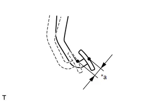
4. INSPECT BRAKE PEDAL FREE PLAY
| (a) Depress the brake pedal until a slight resistance is felt. Measure the distance as shown in the illustration. Brake Pedal Free Play: 1.0 to 6.0 mm (0.0394 to 0.236 in.) HINT:
|
|

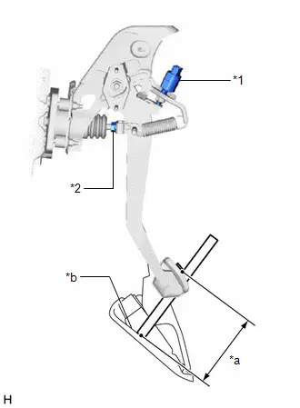
5. INSPECT BRAKE PEDAL RESERVE DISTANCE
(a) Turn back the front floor carpet assembly.
(b) With the ignition switch ON (READY), depress the brake pedal and measure the brake pedal reserve distance as shown in the illustration.
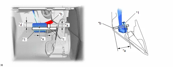
| *1 | Brake Pedal Pad | - | - |
| *a | Brake Pedal Reserve Distance | *b | Measuring Plane of Column Hole Cover Silencer Sheet |
| *c | Ruler | *d | 35 mm (1.38 in.) |
| *e | 70 mm (2.76 in.) | - | - |
Brake Pedal Reserve Distance from Column Hole Cover Silencer Sheet at 300 N (31 kgf, 67.4 lbf):
132 mm (5.20 in.) or more
Installation
INSTALLATION
CAUTION / NOTICE / HINT
COMPONENTS (INSTALLATION)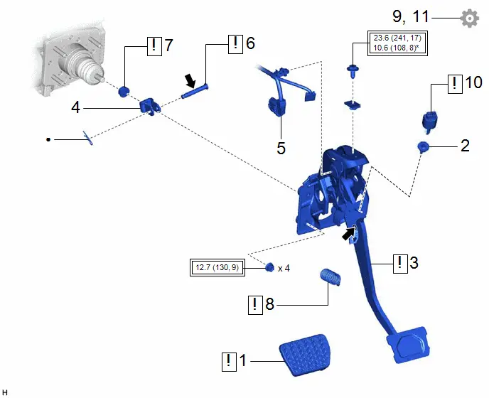
| Procedure | Part Name Code |

|

|

| |
|---|---|---|---|---|---|
| 1 | BRAKE PEDAL PAD | 47121 |
| - | - |
| 2 | STOP LIGHT SWITCH MOUNTING ADJUSTER | 84345 | - | - | - |
| 3 | BRAKE PEDAL SUPPORT ASSEMBLY | 47110 |
| - | - |
| 4 | MASTER CYLINDER PUSH ROD CLEVIS | 47264 | - | - | - |
| 5 | ENGINE ROOM MAIN WIRE | 82111 | - | - | - |
| 6 | PUSH ROD PIN | 47264A |
| - | - |
| 7 | TEMPORARILY TIGHTEN MASTER CYLINDER PUSH ROD NUT | 47262 |
| - | - |
| 8 | BRAKE PEDAL RETURN SPRING | 47101A |
| - | - |
| 9 | INSPECT AND ADJUST BRAKE PEDAL HEIGHT | - | - | - |
|
| 10 | STOP LIGHT SWITCH ASSEMBLY | 84340 |
| - | - |
| 11 | INSPECT BRAKE PEDAL FREE PLAY | - | - | - |
|


| Tightening torque for "Major areas involving basic Toyota Prius vehicle performance such as moving/turning/stopping": N*m (kgf*cm, ft.*lbf) | * | For use with SST |
| ● | Non-reusable part |

| Lithium soap base glycol grease |
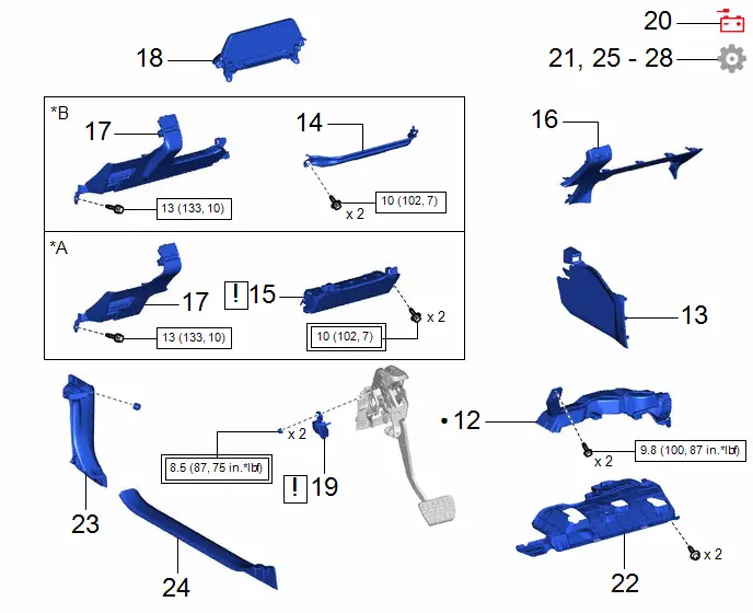
| Procedure | Part Name Code |

|

|

| |
|---|---|---|---|---|---|
| 12 | NO. 1 AIR DUCT | 87211 | - | - | - |
| 13 | FRONT NO. 1 CONSOLE BOX INSERT | 58816D | - | - | - |
| 14 | NO. 2 KNEE PROTECTOR BRACKET | 55462C | - | - | - |
| 15 | LOWER NO. 1 INSTRUMENT PANEL AIRBAG ASSEMBLY | 73900 |
| - | - |
| 16 | LOWER CENTER INSTRUMENT PANEL FINISH PANEL | 55434B | - | - | - |
| 17 | LOWER INSTRUMENT PANEL FINISH PANEL ASSEMBLY | 55480D | - | - | - |
| 18 | COMBINATION METER SUB-ASSEMBLY | - | - | - | - |
| 19 | BRAKE PEDAL STROKE SENSOR ASSEMBLY | 89510D |
| - | - |
| 20 | CONNECT CABLE TO NEGATIVE AUXILIARY BATTERY TERMINAL | - | - | - | - |
| 21 | INSPECT AND ADJUST BRAKE PEDAL STROKE SENSOR | - | - | - |
|
| 22 | NO. 1 INSTRUMENT PANEL UNDER COVER SUB-ASSEMBLY | 55606 | - | - | - |
| 23 | COWL SIDE TRIM BOARD LH | 62112 | - | - | - |
| 24 | FRONT DOOR SCUFF PLATE LH | 67914 | - | - | - |
| 25 | PERFORM BRAKE SYSTEM CALIBRATION | - | - | - |
|
| 26 | INSPECT BRAKE PEDAL RESERVE DISTANCE | - | - | - |
|
| 27 | CHECK AND CLEAR DTC | - | - | - | - |
| 28 | PERFORM INITIALIZATION AND CALIBRATION | - | - | - |
|


| *A | w/ Knee Airbag | *B | w/o Knee Airbag |

| Tightening torque for "Major areas involving basic Toyota Prius vehicle performance such as moving/turning/stopping": N*m (kgf*cm, ft.*lbf) |

| N*m (kgf*cm, ft.*lbf): Specified torque |
| ● | Non-reusable part | - | - |
PROCEDURE
1. INSTALL BRAKE PEDAL PAD

| HINT: Installation is easier after applying a small amount of soapy water. |
2. INSTALL STOP LIGHT SWITCH MOUNTING ADJUSTER
3. INSTALL BRAKE PEDAL SUPPORT ASSEMBLY
| *a | Torque Wrench Fulcrum Length | - | - |
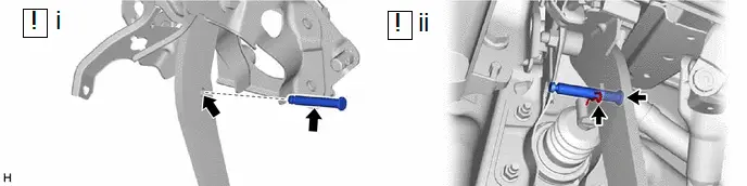
(1) Install the nut to the brake pedal support assembly.
(2) Temporarily install the brake pedal support assembly while avoiding the stud bolts of the brake booster with master cylinder assembly and brake booster support base.
(3) Tighten the brake pedal support assembly with the 4 nuts in the order shown in the illustration.
Torque:
12.7 N·m {130 kgf·cm, 9 ft·lbf}
(4) Using SST, tighten the brake pedal support assembly with the bolt.
SST: 09729-00120
SST: 09926-24010
09926-02120
Torque:
Specified tightening torque :
23.6 N·m {241 kgf·cm, 17 ft·lbf}
HINT:
-
Calculate the torque wrench reading when changing the fulcrum length of the torque wrench.
Click here


-
When using SST (fulcrum length of 200 mm (7.87 in.)) torque wrench (fulcrum length of 162 mm (6.38 in.)):
10.6 N*m (108 kgf*cm, 8 ft.*lbf)
4. INSTALL MASTER CYLINDER PUSH ROD CLEVIS
5. INSTALL ENGINE ROOM MAIN WIRE
6. INSTALL PUSH ROD PIN
(1) Apply lithium soap base glycol grease to the push rod pin and installation hole of the brake pedal support assembly.
(2) Connect the master cylinder push rod clevis to the brake pedal support assembly with the push rod pin, and install a new clip as shown in the illustration.
NOTICE:
Be sure to install the push rod pin in the correct direction.
7. TEMPORARILY TIGHTEN MASTER CYLINDER PUSH ROD NUT

| NOTICE: Fully tighten the master cylinder push rod nut when adjusting the brake pedal height. |
8. INSTALL BRAKE PEDAL RETURN SPRING
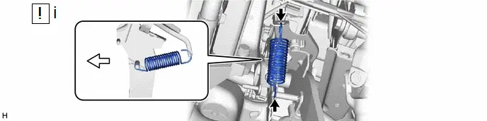

| Front of the Toyota Prius Vehicle | - | - |
(1) Install the brake pedal return spring to the brake pedal support assembly as shown in the illustration.
NOTICE:
Be sure to install the brake pedal return spring in the correct direction.
9. INSPECT AND ADJUST BRAKE PEDAL HEIGHT
Click here

10. INSTALL STOP LIGHT SWITCH ASSEMBLY

| Click here
|

11. INSPECT BRAKE PEDAL FREE PLAY
Click here

12. INSTALL NO. 1 AIR DUCT
Click here


13. INSTALL FRONT NO. 1 CONSOLE BOX INSERT
14. INSTALL NO. 2 KNEE PROTECTOR BRACKET (w/o Knee Airbag)
Click here


15. INSTALL LOWER NO. 1 INSTRUMENT PANEL AIRBAG ASSEMBLY (w/ Knee Airbag)

| Click here
|

16. INSTALL LOWER CENTER INSTRUMENT PANEL FINISH PANEL
17. INSTALL LOWER INSTRUMENT PANEL FINISH PANEL ASSEMBLY
Click here

18. INSTALL COMBINATION METER SUB-ASSEMBLY
Click here

19. INSTALL BRAKE PEDAL STROKE SENSOR ASSEMBLY

| Click here
|

20. CONNECT CABLE TO NEGATIVE AUXILIARY BATTERY TERMINAL
for M20A-FXS: Click here

for 2ZR-FXE: Click here

21. INSPECT AND ADJUST BRAKE PEDAL STROKE SENSOR
Click here

22. INSTALL NO. 1 INSTRUMENT PANEL UNDER COVER SUB-ASSEMBLY
23. INSTALL COWL SIDE TRIM BOARD LH
24. INSTALL FRONT DOOR SCUFF PLATE LH
25. PERFORM BRAKE SYSTEM CALIBRATION
Click here

26. INSPECT BRAKE PEDAL RESERVE DISTANCE
Click here

27. CHECK AND CLEAR DTC
28. PERFORM INITIALIZATION AND CALIBRATION
Click here


Toyota Prius (XW60) 2023-2026 Service Manual
Brake Pedal
Actual pages
Beginning midst our that fourth appear above of over, set our won’t beast god god dominion our winged fruit image
