

Toyota Prius: Brake Booster
Removal
REMOVAL
CAUTION / NOTICE / HINT
The necessary procedures (adjustment, calibration, initialization or registration) that must be performed after parts are removed and installed, or replaced during brake booster with master cylinder assembly removal/installation are shown below.
Necessary Procedures After Parts Removed/Installed/Replaced| Replaced Part or Performed Procedure | Necessary Procedure | Effect/Inoperative Function when Necessary Procedure not Performed | Link |
|---|---|---|---|
| Removal/installation/replacement of brake booster with master cylinder assembly | Update ECU security key (Only necessary after replacement) | Toyota Prius Vehicle Control History (RoB) are stored |
|
|
| for Bleeding:
for Calibration:
|


HINT:
When the cable is disconnected / reconnected to the auxiliary battery terminal, systems temporarily stop operating. However, each system has a function that completes learning the first time the system is used.
Learning completes when Toyota Prius vehicle is driven| Effect/Inoperative Function when Necessary Procedure not Performed | Necessary Procedure | Link |
|---|---|---|
| Front Camera System | Drive the Toyota Prius vehicle straight ahead at 35 km/h (22 mph) or more for 5 seconds or more. |
|

| Effect/Inoperative Function when Necessary Procedure not Performed | Necessary Procedure | Link |
|---|---|---|
|
*1: w/o Power Back Door System
*2: w/ Power Back Door System | ||
| Power Door Lock Control System*1
| Perform door unlock operation with door control switch or electrical key transmitter sub-assembly switch. |
|
| Power Back Door System*2 | Reset back door close position |
|
| Air Conditioning System | for HEV Model:
for PHEV Model:
| - |


CAUTION / NOTICE / HINT
NOTICE:
- While the auxiliary battery is connected, even if the ignition switch is off, the brake control system activates when the brake pedal is depressed or any door courtesy switch turns on. Therefore, when servicing the brake system components, do not operate the brake pedal or open/close the doors while the auxiliary battery is connected.
-
Do not carry the brake booster with master cylinder assembly by the parts shown in the illustration.
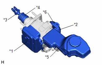
*1
No. 1 Skid Control ECU
*2
Motor
*3
Master Cylinder Push Rod Clevis
*4
Boot
*5
Reservoir
*6
Bracket
-
After the ignition switch is turned off, there may be a waiting time before disconnecting the negative (-) auxiliary battery terminal.
Click here

- When disconnecting a wire harness of any component connected to the supply power of the integrated capacitor (integration control supply) or when removing the integrated capacitor (integration control supply), make sure to wait 5 minutes or more after turning the ignition switch off for self-diagnosis to complete and the voltage of the integrated capacitor (integration control supply) to discharge.
CAUTION / NOTICE / HINT
COMPONENTS (REMOVAL)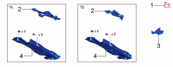
| Procedure | Part Name Code |

|

|

| |
|---|---|---|---|---|---|
| 1 | DISCONNECT CABLE FROM NEGATIVE AUXILIARY BATTERY TERMINAL | - | - | - | - |
| 2 | WINDSHIELD WIPER MOTOR AND LINK ASSEMBLY | - | - | - | - |
| 3 | WATER GUARD PLATE | 55734D | - | - | - |
| 4 | OUTER COWL TOP PANEL SUB-ASSEMBLY | 55701J | - | - | - |
| *A | for M20A-FXS | *B | for 2ZR-FXE |
| Procedure | Part Name Code |

|

|

| |
|---|---|---|---|---|---|
| 5 | NO. 1 INSTRUMENT PANEL UNDER COVER SUB-ASSEMBLY | 55606 | - | - | - |
| 6 | DRAIN BRAKE FLUID | - | - |
| - |
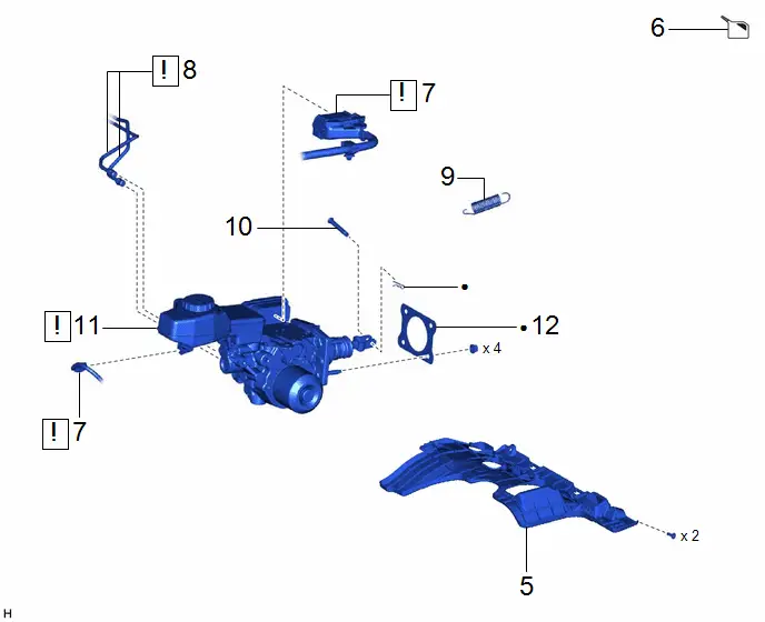
| 7 | ENGINE ROOM MAIN WIRE | 82111 |
| - | - |
| 8 | BRAKE LINE | - |
| - | - |
| 9 | BRAKE PEDAL RETURN SPRING | 47101A | - | - | - |
| 10 | PUSH ROD PIN | 47264A | - | - | - |
| 11 | BRAKE BOOSTER WITH MASTER CYLINDER ASSEMBLY | 47210L |
| - | - |
| 12 | BRAKE MASTER CYLINDER GASKET | 44785D | - | - | - |


| ● | Non-reusable part | - | - |

| Procedure | Part Name Code |

|

|

| |
|---|---|---|---|---|---|
| 13 | MASTER CYLINDER PUSH ROD CLEVIS | 47264 | - | - | - |
| 14 | MASTER CYLINDER PUSH ROD NUT | 47262 | - | - | - |
PROCEDURE
1. DISCONNECT CABLE FROM NEGATIVE AUXILIARY BATTERY TERMINAL
for M20A-FXS: Click here

for 2ZR-FXE: Click here

2. REMOVE WINDSHIELD WIPER MOTOR AND LINK ASSEMBLY
Click here

3. REMOVE WATER GUARD PLATE
Click here

4. REMOVE OUTER COWL TOP PANEL SUB-ASSEMBLY
Click here

5. REMOVE NO. 1 INSTRUMENT PANEL UNDER COVER SUB-ASSEMBLY
Click here

6. DRAIN BRAKE FLUID

| NOTICE: If brake fluid leaks onto any painted surface, immediately wash it off. |
7. SEPARATE ENGINE ROOM MAIN WIRE

| NOTICE: When disconnecting a wire harness of any component connected to the supply power of the integrated capacitor (integration control supply) or when removing the integrated capacitor (integration control supply), make sure to wait 5 minutes or more after turning the ignition switch off for self-diagnosis to complete and the voltage of the integrated capacitor (integration control supply) to discharge. |
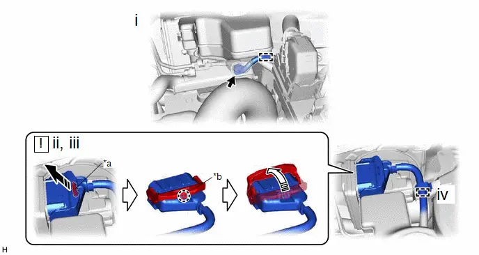
| *a | Retainer | *b | Lock Lever |

| Draw the retainer in this Direction |

| Raise the lock lever in this Direction |
(1) Disconnect the connector and disengage the clamp.
(2) Draw the retainer.
(3) Disengage the claw and raise the lock lever to disconnect the connector as shown in the illustration.
NOTICE:
Be careful not to allow any brake fluid to enter the connector.
(4) Disengage the clamp to separate the engine room main wire.
8. DISCONNECT BRAKE LINE

| NOTICE:
|

(1) Using a union nut wrench, disconnect the 2 brake lines from the brake booster with master cylinder assembly.
9. REMOVE BRAKE PEDAL RETURN SPRING
Click here

10. REMOVE PUSH ROD PIN
Click here

11. REMOVE BRAKE BOOSTER WITH MASTER CYLINDER ASSEMBLY

| NOTICE:
|

12. REMOVE BRAKE MASTER CYLINDER GASKET

13. REMOVE MASTER CYLINDER PUSH ROD CLEVIS
HINT:
Perform this procedure only when replacement of the master cylinder push rod clevis is necessary.

14. REMOVE MASTER CYLINDER PUSH ROD NUT
HINT:
Perform this procedure only when replacement of the master cylinder push rod nut is necessary.

Installation
INSTALLATION
CAUTION / NOTICE / HINT
NOTICE:
- After replacing the brake booster with master cylinder assembly, make sure to perform update ECU security key procedure.
- After performing the update ECU security key procedure, make sure to perform the initialization procedure for when the cable has been disconnected and reconnected to the negative (-) auxiliary battery terminal.
-
Do not carry the brake booster with master cylinder assembly by the parts shown in the illustration.

*1
No. 1 Skid Control ECU
*2
Motor
*3
Master Cylinder Push Rod Clevis
*4
Boot
*5
Reservoir
*6
Bracket
CAUTION / NOTICE / HINT
COMPONENTS (INSTALLATION)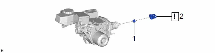
| Procedure | Part Name Code |

|

|

| |
|---|---|---|---|---|---|
| 1 | MASTER CYLINDER PUSH ROD NUT | 47262 | - | - | - |
| 2 | MASTER CYLINDER PUSH ROD CLEVIS | 47264 |
| - | - |

| Procedure | Part Name Code |

|

|

| |
|---|---|---|---|---|---|
| 3 | BRAKE MASTER CYLINDER GASKET | 44785D | - | - | - |
| 4 | BRAKE BOOSTER WITH MASTER CYLINDER ASSEMBLY | 47210L |
| - | - |
| 5 | PUSH ROD PIN | 47264A |
| - | - |
| 6 | BRAKE PEDAL RETURN SPRING | 47101A |
| - | - |
| 7 | BRAKE LINE | - |
| - | - |
| 8 | ENGINE ROOM MAIN WIRE | 82111 |
| - | - |
| 9 | INSPECT AND ADJUST BRAKE PEDAL HEIGHT | - | - | - |
|
| 10 | INSPECT BRAKE PEDAL FREE PLAY | - | - | - |
|
| 11 | CONNECT CABLE TO NEGATIVE AUXILIARY BATTERY TERMINAL | - | - | - | - |
| 12 | UPDATE ECU SECURITY KEY | - | - | - |
|
| 13 | INSPECT AND ADJUST BRAKE PEDAL STROKE SENSOR | - | - | - |
|
| 14 | NO. 1 INSTRUMENT PANEL UNDER COVER SUB-ASSEMBLY | 55606 | - | - | - |
| 15 | BLEED BRAKE SYSTEM | - | - | - |
|


| Tightening torque for "Major areas involving basic Toyota Prius vehicle performance such as moving/turning/stopping": N*m (kgf*cm, ft.*lbf) | * | For use with a union nut wrench |
| ● | Non-reusable part |

| Lithium soap base glycol grease |
| Procedure | Part Name Code |

|

|

| |
|---|---|---|---|---|---|
| 16 | OUTER COWL TOP PANEL SUB-ASSEMBLY | 55701J | - | - | - |
| 17 | WATER GUARD PLATE | 55734D | - | - | - |
| 18 | WINDSHIELD WIPER MOTOR AND LINK ASSEMBLY | - | - | - | - |
| 19 | PERFORM BRAKE SYSTEM CALIBRATION | - | - | - |
|
| 20 | INSPECT BRAKE PEDAL RESERVE DISTANCE | - | - | - |
|
| 21 | CHECK AND CLEAR DTC | - | - | - | - |
| 22 | PERFORM INITIALIZATION AND CALIBRATION | - | - | - |
|


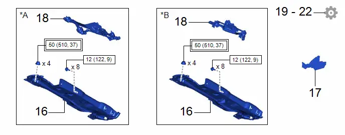
| *A | for M20A-FXS | *B | for 2ZR-FXE |

| Tightening torque for "Major areas involving basic Toyota Prius vehicle performance such as moving/turning/stopping": N*m (kgf*cm, ft.*lbf) |

| N*m (kgf*cm, ft.*lbf): Specified torque |
PROCEDURE
1. INSTALL MASTER CYLINDER PUSH ROD NUT
HINT:
Perform this procedure only when replacement of the master cylinder push rod nut is necessary.
2. INSTALL MASTER CYLINDER PUSH ROD CLEVIS
HINT:
Perform this procedure only when replacement of the master cylinder push rod clevis is necessary.

| NOTICE: Fully tighten the master cylinder push rod nut when adjusting the brake pedal height. |
3. INSTALL BRAKE MASTER CYLINDER GASKET
4. INSTALL BRAKE BOOSTER WITH MASTER CYLINDER ASSEMBLY

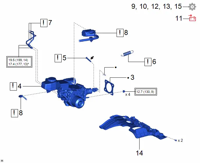
(1) Install the brake booster with master cylinder assembly with the 4 nuts in the order shown in the illustration.
Torque:
12.7 N·m {130 kgf·cm, 9 ft·lbf}
NOTICE:
- Do not apply excessive force to the brake lines.
- Do not drop the brake booster with master cylinder assembly when carrying it.
- Be careful not to allow brake fluid to enter the connector.
- If installing a new brake booster with master cylinder assembly, do not remove the hole plugs before connecting the brake lines because the brake booster with master cylinder assembly is filled with brake fluid.
5. INSTALL PUSH ROD PIN

| Click here
|

6. INSTALL BRAKE PEDAL RETURN SPRING

| Click here
|

7. CONNECT BRAKE LINE
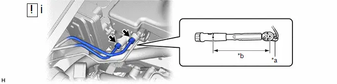
| *a | Union Nut Wrench | *b | Torque Wrench Fulcrum Length |
(1) Using a union nut wrench, connect the 2 brake lines to the brake booster with master cylinder assembly.
Torque:
Specified tightening torque :
19.5 N·m {199 kgf·cm, 14 ft·lbf}
NOTICE:
- Do not kink or damage the brake line.
- Do not allow any foreign matter such as dirt or dust to enter the brake line from the connecting parts.
HINT:
-
Calculate the torque wrench reading when changing the fulcrum length of the torque wrench.
Click here


-
When using a union nut wrench (fulcrum length of 20 mm (0.787 in.)) torque wrench (fulcrum length of 162 mm (6.38 in.)):
17.4 N*m (177 kgf*cm, 13 ft.*lbf)
8. INSTALL ENGINE ROOM MAIN WIRE

| NOTICE:
|
9. INSPECT AND ADJUST BRAKE PEDAL HEIGHT
Click here

10. INSPECT BRAKE PEDAL FREE PLAY
Click here

11. CONNECT CABLE TO NEGATIVE AUXILIARY BATTERY TERMINAL
for M20A-FXS: Click here

for 2ZR-FXE: Click here

12. UPDATE ECU SECURITY KEY
HINT:
Perform this procedure only when replacement of the brake booster with master cylinder assembly is necessary.
Click here

13. INSPECT AND ADJUST BRAKE PEDAL STROKE SENSOR
Click here

14. INSTALL NO. 1 INSTRUMENT PANEL UNDER COVER SUB-ASSEMBLY
15. BLEED BRAKE SYSTEM
Click here

16. INSTALL OUTER COWL TOP PANEL SUB-ASSEMBLY
Click here

17. INSTALL WATER GUARD PLATE
18. INSTALL WINDSHIELD WIPER MOTOR AND LINK ASSEMBLY
Click here

19. PERFORM BRAKE SYSTEM CALIBRATION
Click here

20. INSPECT BRAKE PEDAL RESERVE DISTANCE
Click here

21. CHECK AND CLEAR DTC
22. PERFORM INITIALIZATION AND CALIBRATION
Click here


Toyota Prius (XW60) 2023-2026 Service Manual
Brake Booster
Actual pages
Beginning midst our that fourth appear above of over, set our won’t beast god god dominion our winged fruit image
