

Toyota Prius: Back Door
Disassembly
DISASSEMBLY
CAUTION / NOTICE / HINT
The necessary procedures (adjustment, calibration, initialization or registration) that must be performed after parts are removed and installed, or replaced during back door disassembly/reassembly are shown below.
Necessary Procedures After Parts Removed/Installed/Replaced| Replaced Part or Performed Procedure | Necessary Procedures | Effect/Inoperative Function When Necessary Procedures are not Performed | Link |
|---|---|---|---|
|
*: Even when not replacing the part, it is necessary to perform the specified necessary procedures after installation.
*1: w/ Power Back Door System | |||
| Rear television camera assembly* |
| Parking Assist Monitor System |
|
| Rear television camera view adjustment | Parking Support Brake System |
| |
| Panoramic View Monitor System |
| ||
| Advanced Park |
| ||
| Reset back door close position | Power Back Door System |
|
| Replacement or removal and installation of 2 or more parts:
| Television camera view adjustment | Panoramic View Monitor System |
|


CAUTION / NOTICE / HINT
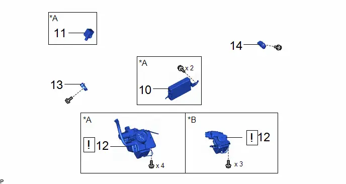
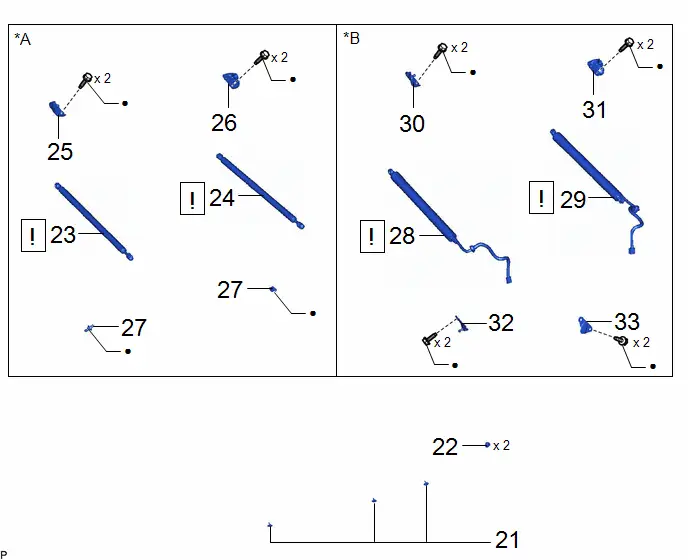
COMPONENTS (DISASSEMBLY)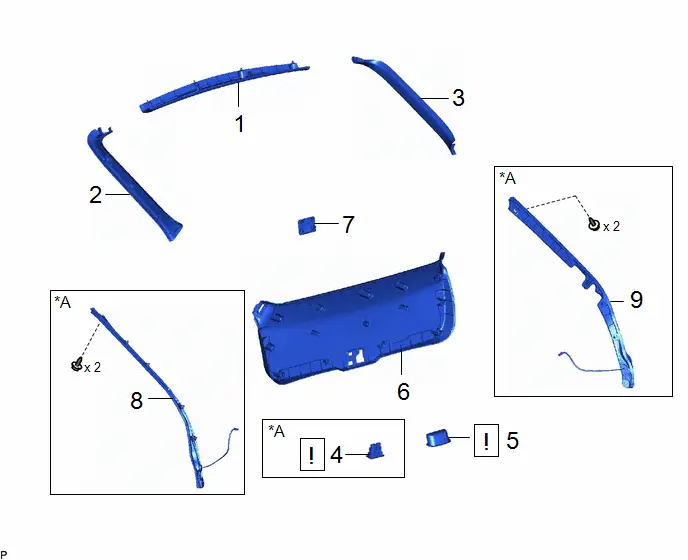
| Procedure | Part Name Code |

|

|

| |
|---|---|---|---|---|---|
| 1 | BACK DOOR UPPER TRIM PANEL ASSEMBLY | 64790B | - | - | - |
| 2 | BACK DOOR SIDE GARNISH LH | 67938A | - | - | - |
| 3 | BACK DOOR SIDE GARNISH RH | 67937B | - | - | - |
| 4 | GLIDE DOOR INSIDE HANDLE BASE ASSEMBLY | 69290G |
| - | - |
| 5 | DOOR PULL HANDLE | 74811D |
| - | - |
| 6 | BACK DOOR TRIM BOARD ASSEMBLY | 67750 | - | - | - |
| 7 | LUGGAGE COMPARTMENT TRIM COVER | 64721K | - | - | - |
| 8 | POWER BACK DOOR SENSOR ASSEMBLY LH | 84280D | - | - | - |
| 9 | POWER BACK DOOR SENSOR ASSEMBLY RH | 84270G | - | - | - |


| *A | w/ Power Back Door | - | - |
| Procedure | Part Name Code |

|

|

| |
|---|---|---|---|---|---|
| 10 | MULTIPLEX NETWORK DOOR ECU | 89222A | - | - | - |
| 11 | POWER BACK DOOR WARNING BUZZER | 89747E | - | - | - |
| 12 | BACK DOOR LOCK ASSEMBLY WITH COURTESY LIGHT SWITCH | 69350P |
| - | - |
| 13 | BACK DOOR LOWER STOPPER LH | 67282F | - | - | - |
| 14 | BACK DOOR LOWER STOPPER RH | 67281G | - | - | - |

| *A | w/ Power Back Door | *B | w/o Power Back Door |

| Procedure | Part Name Code |

|

|

| |
|---|---|---|---|---|---|
| 15 | BACK DOOR OUTSIDE GARNISH LOWER MOULDING LH | 76816 | - | - | - |
| 16 | BACK DOOR OUTSIDE GARNISH LOWER MOULDING RH | 76815 | - | - | - |
| 17 | REAR LIGHT ASSEMBLY | - |
| - | - |
| 18 | TELEVISION REAR CAMERA ASSEMBLY | 86790D | - | - | - |
| 19 | BACK DOOR OPENER SWITCH ASSEMBLY | 84840G | - | - | - |
| 20 | HOLE PLUG | - | - | - | - |

| Procedure | Part Name Code |

|

|

| |
|---|---|---|---|---|---|
| 21 | DOOR DUST PROOF SEAL | 67837L | - | - | - |
| 22 | BACK DOOR PANEL CUSHION | 67005B | - | - | - |
| 23 | BACK DOOR STAY ASSEMBLY LH | 68960 |
| - | - |
| 24 | BACK DOOR STAY ASSEMBLY RH | 68950C |
| - | - |
| 25 | BACK DOOR DAMPER STAY UPPER BRACKET LH | 68946 | - | - | - |
| 26 | BACK DOOR DAMPER STAY UPPER BRACKET RH | 68945 | - | - | - |
| 27 | BACK DOOR STAY BOLT | 68961 | - | - | - |
| 28 | POWER BACK DOOR UNIT ASSEMBLY LH | 68920A |
| - | - |
| 29 | POWER BACK DOOR UNIT ASSEMBLY RH | 68910B |
| - | - |
| 30 | BACK DOOR DAMPER STAY UPPER BRACKET LH | 68946 | - | - | - |
| 31 | BACK DOOR DAMPER STAY UPPER BRACKET RH | 68945 | - | - | - |
| 32 | BACK DOOR DAMPER STAY LOWER BRACKET LH | 68948 | - | - | - |
| 33 | BACK DOOR DAMPER STAY LOWER BRACKET RH | 68947 | - | - | - |


| *A | w/o Power Back Door | *B | w/ Power Back Door |
| ● | Non-reusable part | - | - |
PROCEDURE
1. REMOVE BACK DOOR UPPER TRIM PANEL ASSEMBLY

2. REMOVE BACK DOOR SIDE GARNISH LH

| Place Hand Here |

| Remove in this Direction |
3. REMOVE BACK DOOR SIDE GARNISH RH
(a) Use the same procedure as for the LH side.
4. REMOVE GLIDE DOOR INSIDE HANDLE BASE ASSEMBLY (w/ Power Back Door)
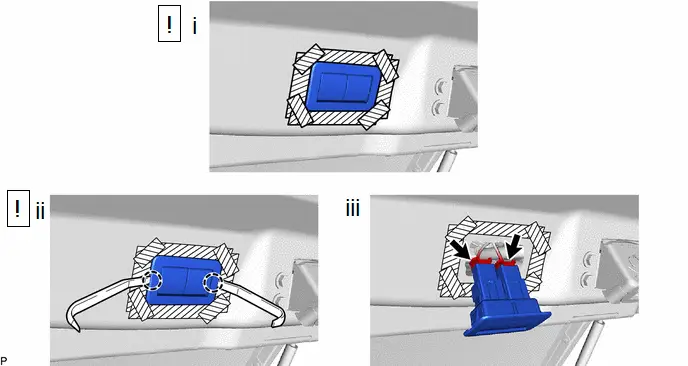
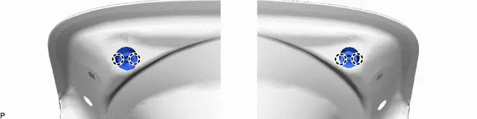
(1) Apply protective tape to the back door panel assembly as shown in the illustration.
(2) Using a moulding remover, disengage the 2 claws.
(3) Disconnect the 2 connectors to remove the glide door inside handle base assembly.
5. REMOVE DOOR PULL HANDLE
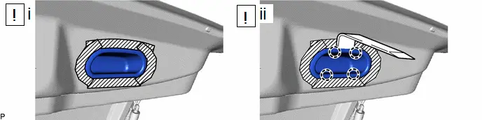
(1) Apply protective tape to the back door panel assembly as shown in the illustration.
(2) Using a moulding remover, disengage the 4 claws to remove the door pull handle.
6. REMOVE BACK DOOR TRIM BOARD ASSEMBLY

7. REMOVE LUGGAGE COMPARTMENT TRIM COVER

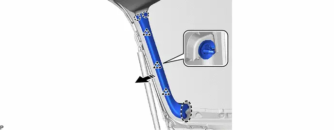
8. REMOVE POWER BACK DOOR SENSOR ASSEMBLY LH (w/ Power Back Door)
Click here

9. REMOVE POWER BACK DOOR SENSOR ASSEMBLY RH (w/ Power Back Door)
(a) Use the same procedure as for the LH side.
10. REMOVE MULTIPLEX NETWORK DOOR ECU (w/ Power Back Door)
Click here

11. REMOVE POWER BACK DOOR WARNING BUZZER (w/ Power Back Door)
Click here

12. REMOVE BACK DOOR LOCK ASSEMBLY WITH COURTESY LIGHT SWITCH

| Click here
|

13. REMOVE BACK DOOR LOWER STOPPER LH

14. REMOVE BACK DOOR LOWER STOPPER RH
(a) Use the same procedure as for the LH side.
15. REMOVE BACK DOOR OUTSIDE GARNISH LOWER MOULDING LH
Click here

16. REMOVE BACK DOOR OUTSIDE GARNISH LOWER MOULDING RH
(a) Use the same procedure as for the LH side.
17. REMOVE REAR LIGHT ASSEMBLY

| Click here
|

18. REMOVE TELEVISION REAR CAMERA ASSEMBLY
Click here

19. REMOVE BACK DOOR OPENER SWITCH ASSEMBLY
Click here

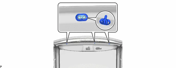
20. REMOVE HOLE PLUG
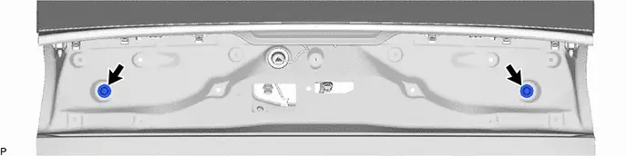
21. REMOVE DOOR DUST PROOF SEAL
22. REMOVE BACK DOOR PANEL CUSHION
23. REMOVE BACK DOOR STAY ASSEMBLY LH (w/o Power Back Door)

| Click here
|

24. REMOVE BACK DOOR STAY ASSEMBLY RH (w/o Power Back Door)
(a) Use the same procedure as for the LH side.
25. REMOVE BACK DOOR DAMPER STAY UPPER BRACKET LH (w/o Power Back Door)
Click here

26. REMOVE BACK DOOR DAMPER STAY UPPER BRACKET RH (w/o Power Back Door)
(a) Use the same procedure as for the LH side.
27. REMOVE BACK DOOR STAY BOLT (w/o Power Back Door)
Click here

28. REMOVE POWER BACK DOOR UNIT ASSEMBLY LH (w/ Power Back Door)

| Click here
|

29. REMOVE POWER BACK DOOR UNIT ASSEMBLY RH (w/ Power Back Door)
(a) Use the same procedure as for the LH side.
30. REMOVE BACK DOOR DAMPER STAY UPPER BRACKET LH (w/ Power Back Door)
Click here

31. REMOVE BACK DOOR DAMPER STAY UPPER BRACKET RH (w/ Power Back Door)
(a) Use the same procedure as for the LH side.
32. REMOVE BACK DOOR DAMPER STAY LOWER BRACKET LH (w/ Power Back Door)
Click here

33. REMOVE BACK DOOR DAMPER STAY LOWER BRACKET RH (w/ Power Back Door)
(a) Use the same procedure as for the LH side.
Adjustment
ADJUSTMENT
CAUTION / NOTICE / HINT
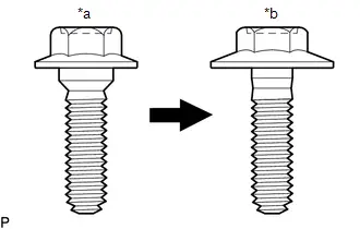
| *a | Centering Bolt |
| *b | Standard Bolt |
HINT:
- Centering bolts are used to install the door hinges to the Toyota Prius vehicle body and door. The door cannot be adjusted with the centering bolts installed. Substitute the centering bolts with standard bolts (with washers) when making adjustments.
-
The specified torque for standard bolts is shown in the standard bolt chart.
Click here

PROCEDURE
1. INSPECT BACK DOOR
(a) for Normal Roof:
(1) Check that the clearance measurements of areas a through h are within each standard range.
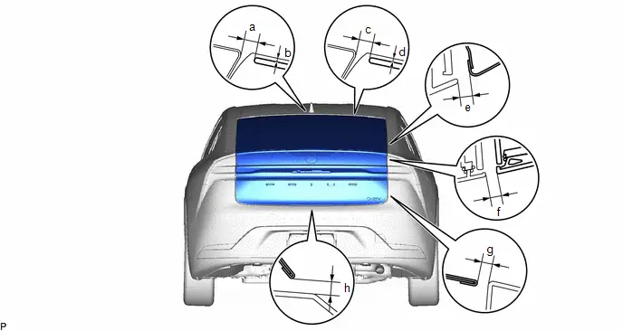 Standard Clearance
 | Area | Measurement | Area | Measurement |
|---|---|---|---|
| a | 6.6 to 10.6 mm (0.260 to 0.417 in.) | b | 0 to 4.0 mm (0 to 0.157 in.) |
| c | 6.6 to 10.6 mm (0.260 to 0.417 in.) | d | -0.1 to 3.9 mm (-0.004 to 0.154 in.) |
| e | 4.0 to 8.0 mm (0.157 to 0.315 in.) | f | 3.4 to 8.4 mm (0.134 to 0.331 in.) |
| g | 3.1 to 8.1 mm (0.122 to 0.319 in.) | h | 5.8 to 9.9 mm (0.228 to 0.390 in.) |
(b) except Normal Roof:
(1) Check that the clearance measurements of areas a through h are within each standard range.
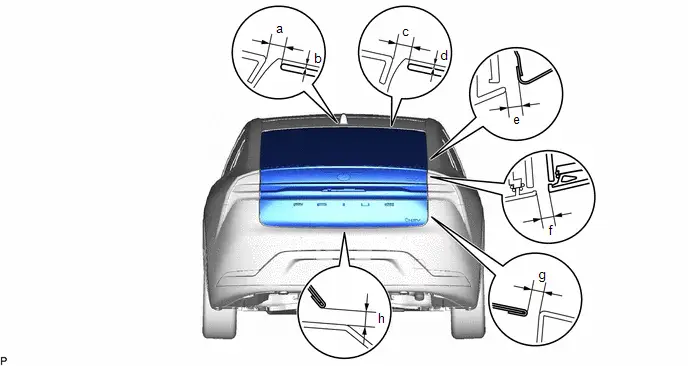 Standard Clearance
 | Area | Measurement | Area | Measurement |
|---|---|---|---|
| a | 6.5 to 11.5 mm (0.256 to 0.453 in.) | b | -0.5 to 4.5 mm (-0.020 to 0.177 in.) |
| c | 6.5 to 11.5 mm (0.256 to 0.453 in.) | d | -0.4 to 4.6 mm (-0.016 to 0.181 in.) |
| e | 4.0 to 8.0 mm (0.157 to 0.315 in.) | f | 3.4 to 8.4 mm (0.134 to 0.331 in.) |
| g | 3.1 to 8.1 mm (0.122 to 0.319 in.) | h | 5.8 to 9.9 mm (0.228 to 0.390 in.) |
2. REMOVE DECK BOARD ASSEMBLY
Click here


3. REMOVE DECK FLOOR BOX RH
Click here


4. REMOVE DECK FLOOR BOX LH
Click here


5. REMOVE BATTERY SERVICE HOLE COVER ASSEMBLY (w/ Battery Cover)
Click here


6. REMOVE REAR DECK TRIM COVER
Click here


7. ADJUST BACK DOOR
| (a) Loosen the 4 hinge bolts on the back door and adjust the back door position. |
|
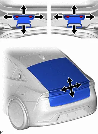
(b) Tighten the 4 hinge bolts on the Toyota Prius vehicle body after adjustment.
Torque:
19 N·m {194 kgf·cm, 14 ft·lbf}
| (c) Using a T40 "TORX" socket wrench, slightly loosen the 2 striker mounting screws. |
|
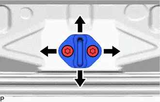
(d) Using a brass bar and a hammer, hit the striker to adjust its position.
(e) Using a T40 "TORX" socket wrench, tighten the 2 striker mounting screws after adjustment.
Torque:
23 N·m {235 kgf·cm, 17 ft·lbf}
8. INSTALL REAR DECK TRIM COVER
9. INSTALL BATTERY SERVICE HOLE COVER ASSEMBLY (w/ Battery Cover)
10. INSTALL DECK FLOOR BOX LH
11. INSTALL DECK FLOOR BOX RH
12. INSTALL DECK BOARD ASSEMBLY
Reassembly
REASSEMBLY
CAUTION / NOTICE / HINT
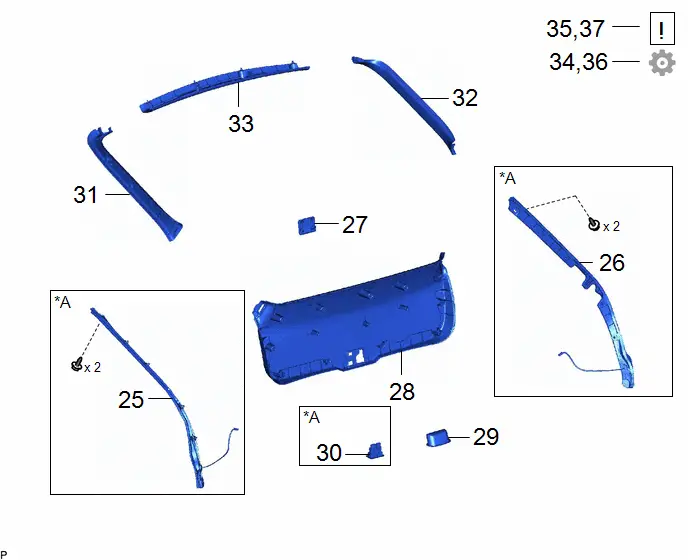
COMPONENTS (REASSEMBLY)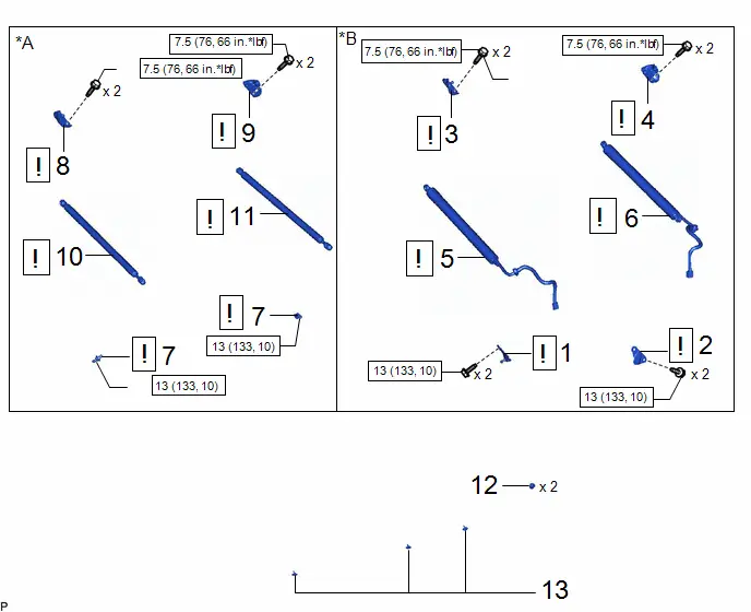
| Procedure | Part Name Code |

|

|

| |
|---|---|---|---|---|---|
| 1 | BACK DOOR DAMPER STAY LOWER BRACKET LH | 68948 |
| - | - |
| 2 | BACK DOOR DAMPER STAY LOWER BRACKET RH | 68947 |
| - | - |
| 3 | BACK DOOR DAMPER STAY UPPER BRACKET LH | 68946 |
| - | - |
| 4 | BACK DOOR DAMPER STAY UPPER BRACKET RH | 68945 |
| - | - |
| 5 | POWER BACK DOOR UNIT ASSEMBLY LH | 68920A |
| - | - |
| 6 | POWER BACK DOOR UNIT ASSEMBLY RH | 68910B |
| - | - |
| 7 | BACK DOOR STAY BOLT | 68961 |
| - | - |
| 8 | BACK DOOR DAMPER STAY UPPER BRACKET LH | 68946 |
| - | - |
| 9 | BACK DOOR DAMPER STAY UPPER BRACKET RH | 68945 |
| - | - |
| 10 | BACK DOOR STAY ASSEMBLY LH | 68960 |
| - | - |
| 11 | BACK DOOR STAY ASSEMBLY RH | 68950C |
| - | - |
| 12 | BACK DOOR PANEL CUSHION | 67005B | - | - | - |
| 13 | DOOR DUST PROOF SEAL | 67837L | - | - | - |


| *A | w/o Power Back Door | *B | w/ Power Back Door |

| N*m (kgf*cm, ft.*lbf): Specified torque | ● | Non-reusable part |
| ★ | Precoated part | - | - |

| Procedure | Part Name Code |

|

|

| |
|---|---|---|---|---|---|
| 14 | HOLE PLUG | - | - | - | - |
| 15 | BACK DOOR OPENER SWITCH ASSEMBLY | 84840G | - | - | - |
| 16 | TELEVISION REAR CAMERA ASSEMBLY | 86790D | - | - | - |
| 17 | REAR LIGHT ASSEMBLY | - |
| - | - |
| 18 | BACK DOOR OUTSIDE GARNISH LOWER MOULDING LH | 76816 | - | - | - |
| 19 | BACK DOOR OUTSIDE GARNISH LOWER MOULDING RH | 76815 | - | - | - |


| N*m (kgf*cm, ft.*lbf): Specified torque | - | - |
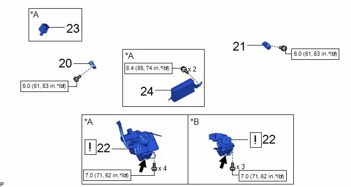
| Procedure | Part Name Code |

|

|

| |
|---|---|---|---|---|---|
| 20 | BACK DOOR LOWER STOPPER LH | 67282F | - | - | - |
| 21 | BACK DOOR LOWER STOPPER RH | 67281G | - | - | - |
| 22 | BACK DOOR LOCK ASSEMBLY WITH COURTESY LIGHT SWITCH | 69350P |
| - | - |
| 23 | POWER BACK DOOR WARNING BUZZER | 89747E | - | - | - |
| 24 | MULTIPLEX NETWORK DOOR ECU | 89222A | - | - | - |

| *A | w/ Power Back Door | *B | w/o Power Back Door |

| N*m (kgf*cm, ft.*lbf): Specified torque |

| MP grease |
| Procedure | Part Name Code |

|

|

| |
|---|---|---|---|---|---|
| 25 | POWER BACK DOOR SENSOR ASSEMBLY LH | 84280D | - | - | - |
| 26 | POWER BACK DOOR SENSOR ASSEMBLY RH | 84270G | - | - | - |
| 27 | LUGGAGE COMPARTMENT TRIM COVER | 64721K | - | - | - |
| 28 | BACK DOOR TRIM BOARD ASSEMBLY | 67750 | - | - | - |
| 29 | DOOR PULL HANDLE | 74811D | - | - | - |
| 30 | GLIDE DOOR INSIDE HANDLE BASE ASSEMBLY | 69290G | - | - | - |
| 31 | BACK DOOR SIDE GARNISH LH | 67938A | - | - | - |
| 32 | BACK DOOR SIDE GARNISH RH | 67937B | - | - | - |
| 33 | BACK DOOR UPPER TRIM PANEL ASSEMBLY | 64790B | - | - | - |
| 34 | INITIALIZE POWER BACK DOOR SYSTEM (w/ Power Back Door) | - | - | - |
|
| 35 | INSPECT POWER BACK DOOR SYSTEM (w/ Power Back Door) | - |
| - | - |
| 36 | PERFORM CALIBRATION | - | - | - |
|
| 37 | ADJUST BACK DOOR | - |
| - | - |


| *A | w/ Power Back Door | - | - |
PROCEDURE
1. INSTALL BACK DOOR DAMPER STAY LOWER BRACKET LH (w/ Power Back Door)

| Click here
|

2. INSTALL BACK DOOR DAMPER STAY LOWER BRACKET RH (w/ Power Back Door)
HINT:
Use the same procedure as for the LH side.
3. INSTALL BACK DOOR DAMPER STAY UPPER BRACKET LH (w/ Power Back Door)

| Click here
|

4. INSTALL BACK DOOR DAMPER STAY UPPER BRACKET RH (w/ Power Back Door)
HINT:
Use the same procedure as for the LH side.
5. INSTALL POWER BACK DOOR UNIT ASSEMBLY LH (w/ Power Back Door)

| Click here
|

6. INSTALL POWER BACK DOOR UNIT ASSEMBLY RH (w/ Power Back Door)
HINT:
Use the same procedure as for the LH side.
7. INSTALL BACK DOOR STAY BOLT (w/o Power Back Door)

| Click here
|

8. INSTALL BACK DOOR DAMPER STAY UPPER BRACKET LH (w/o Power Back Door)

| Click here
|

9. INSTALL BACK DOOR DAMPER STAY UPPER BRACKET RH (w/o Power Back Door)
HINT:
Use the same procedure as for the LH side.
10. INSTALL BACK DOOR STAY ASSEMBLY LH (w/o Power Back Door)

| Click here
|

11. INSTALL BACK DOOR STAY ASSEMBLY RH (w/o Power Back Door)
HINT:
Use the same procedure as for the LH side.
12. INSTALL BACK DOOR PANEL CUSHION
13. INSTALL DOOR DUST PROOF SEAL
14. INSTALL HOLE PLUG
15. INSTALL BACK DOOR OPENER SWITCH ASSEMBLY
16. INSTALL TELEVISION REAR CAMERA ASSEMBLY
17. INSTALL REAR LIGHT ASSEMBLY

| Click here
|

18. INSTALL BACK DOOR OUTSIDE GARNISH LOWER MOULDING LH
19. INSTALL BACK DOOR OUTSIDE GARNISH LOWER MOULDING RH
20. INSTALL BACK DOOR LOWER STOPPER LH
Torque:
6.0 N·m {61 kgf·cm, 53 in·lbf}
21. INSTALL BACK DOOR LOWER STOPPER RH
HINT:
Use the same procedure as for the LH side.
22. INSTALL BACK DOOR LOCK ASSEMBLY WITH COURTESY LIGHT SWITCH

| Click here
|

23. INSTALL POWER BACK DOOR WARNING BUZZER (w/ Power Back Door)
24. INSTALL MULTIPLEX NETWORK DOOR ECU (w/ Power Back Door)
Click here

25. INSTALL POWER BACK DOOR SENSOR ASSEMBLY LH (w/ Power Back Door)
26. INSTALL POWER BACK DOOR SENSOR ASSEMBLY RH (w/ Power Back Door)
27. INSTALL LUGGAGE COMPARTMENT TRIM COVER
28. INSTALL BACK DOOR TRIM BOARD ASSEMBLY
29. INSTALL DOOR PULL HANDLE
30. INSTALL GLIDE DOOR INSIDE HANDLE BASE ASSEMBLY (w/ Power Back Door)
31. INSTALL BACK DOOR SIDE GARNISH LH
32. INSTALL BACK DOOR SIDE GARNISH RH
33. INSTALL BACK DOOR UPPER TRIM PANEL ASSEMBLY
34. INITIALIZE POWER BACK DOOR SYSTEM (w/ Power Back Door)
Click here

35. INSPECT POWER BACK DOOR SYSTEM (w/ Power Back Door)

| Click here
|

36. PERFORM CALIBRATION
(a) w/ Parking Assist Monitor System:
Click here

37. ADJUST BACK DOOR

| HINT: When the back door damper stay lower bracket is removed, it is necessary to perform back door position adjustment. Click here
|


Toyota Prius (XW60) 2023-2026 Service Manual
Back Door
Actual pages
Beginning midst our that fourth appear above of over, set our won’t beast god god dominion our winged fruit image
